Table of Contents
Advertisement
Quick Links
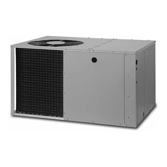
P7RF-K / PPA3RFX-K SERIES
INSTALLATION INSTRUCTIONS
SINGLE PACKAGE AIR CONDITIONER - 2 STAGE, R410A
It is your responsibility to know this product better than your customer. This includes being
able to install the product according to strict safety guidelines and instructing the customer on
how to operate and maintain the equipment for the life of the product. Safety should always be
the deciding factor when installing this product and using common sense plays an important
role as well. Pay attention to all safety warnings and any other special notes highlighted in the
manual. Improper installation of the furnace or failure to follow safety warnings could result in
serious injury, death, or property damage.
These instructions are primarily intended to assist qualified individuals experienced in the proper
installation of this appliance. Some local codes require licensed installation/service personnel
for this type of equipment. Please read all instructions carefully before starting the installation.
Return these instructions to the customer's package for future reference.
DO NOT DESTROY. PLEASE READ CAREFULLY & KEEP IN A SAFE PLACE FOR FUTURE REFERENCE.
IMPORTANT
ATTENTION INSTALLERS:
16 SEER
Advertisement
Table of Contents

Related Manuals for Nortek P7RF-K Series


Summary of Contents for Nortek P7RF-K Series
- Page 1 P7RF-K / PPA3RFX-K SERIES 16 SEER INSTALLATION INSTRUCTIONS SINGLE PACKAGE AIR CONDITIONER - 2 STAGE, R410A IMPORTANT ATTENTION INSTALLERS: It is your responsibility to know this product better than your customer. This includes being able to install the product according to strict safety guidelines and instructing the customer on how to operate and maintain the equipment for the life of the product.
-
Page 2: Table Of Contents
TABLE OF CONTENTS IMPORTANT SAFETY INFORMATION Please read all instructions before servicing this equipment. IMPORTANT SAFETY INFORMATION ......2 Pay attention to all safety warnings and any other special GENERAL INFORMATION ..........3 notes highlighted in the manual. Safety markings are used Before You Install this Unit .......... -
Page 3: General Information
√ Please consult your dealer for maintenance information WARNING: and availability of maintenance contracts. Please read all instructions before installing the unit. The information listed below must be followed Locating the Air Conditioner during the installation, service, and operation • Survey the job site to determine the best location for mounting of this unit. -
Page 4: Air Conditioner Installation
AIR CONDITIONER INSTALLATION Multiple Duct Application Single Duct Application Unpacking the Unit It is recommended that the unit be unpacked at the installation site to minimize damage due to handling. CAUTION: Do not tip the unit on its side. Oil may enter the compressor cylinders and cause starting trouble. -
Page 5: Locating & Installing The Return Air Assembly
Locating & Installing the Supply Damper(s) CAUTION: If installing this air conditioning system in conjunction with a furnace, a damper must be installed in the furnace base assembly to prevent cold air from being discharged around the heat exchanger. Damage to the heat exchanger and asphyxiation may occur if a damper is not installed. -
Page 6: Electrical Connections
COPPER WIRE SIZE — AWG (1% Voltage Drop) Supply Wire Length-Feet Supply Circuit Ampacity Line Voltage Low Voltage Figure 7. Power Entry Locations ELECTRICAL CONNECTIONS Wire Size based on N.E.C. for 60° type copper conductors. Table 1. Copper Wire Size WARNING: ELECTRICAL SHOCK, FIRE OR Recommended T-Stat Wire... -
Page 7: Grounding
Grounding • The low voltage wires must be properly connected. Route 24V control wires through the sealing grommet near the power entrance. See Figure 7 (page 6). Connect the control wires WARNING: to the defrost board and blower relay wire. Recommended wire gauge and wire lengths for typical thermostat connections The unit cabinet must have an uninterrupted or are listed in... -
Page 8: Cooling Mode
2 Stage Heat with Single Stage Heating Thermostat - If a single CAUTION: stage heat thermostat is used and 2 stage heat is desired, an optional outdoor thermostat may be installed. Connect To avoid personal injury or property damage, the optional outdoor thermostat between the W1 (BROWN) connection and ORANGE wire in the outdoor unit. -
Page 9: Air Circulation
COMPONENT FUNCTIONS 9. Instruct the homeowner on unit and thermostat operation and filter servicing. High Pressure Switch (HPS) - A high-pressure switch is factory- installed and located in the liquid line internal to the unit. The Air Circulation switch is designed to protect the system when very high pressures Leave the thermostat system mode on OFF, and set the fan occur during abnormal conditions. - Page 10 2 Ton Charging Chart Remove refrigerant when above curve Add refrigerant when below curve Liquid Temperature ( ° F ) Figure 8. Charging Chart for 2 ton Units 3 Ton Charging Chart Remove refrigerant when above curve Add refrigerant when below curve Liquid Temperature ( °...
- Page 11 4 Ton Charging Chart Remove refrigerant when above curve Add refrigerant when below curve Liquid Temperature ( ° F ) Figure 10. Charging Chart for 4 ton Units 5 Ton Charging Chart Remove refrigerant when above curve Add refrigerant when below curve Liquid Temperature ( °...
-
Page 12: Figures & Tables
FIGURES & TABLES Top View 3” Rear Opening for View Opening for 14" Diameter 12" Diameter Return Duct Supply Duct 10.15 9.15 1.75” Ø Electric Heater 3.15 Power Supply 17.50 1” 1.13” Ø Power Supply .88” Ø Low Voltage Supply Control Blower Access Panel Access... -
Page 13: Electrical Information
Electrical Information 5 Wire 2 Stage Cool / 1 Stage Heat T-Stat 6 Wire 2 Stage Heat / Cool T-Stat Two-Stage Electric Heat Single Stage Electric Heat RED - 24VAC RED - 24VAC YELLOW - S1 COOL YELLOW - S1 COOL GREEN - FAN GREEN - FAN BROWN... - Page 14 Figure 14. Wiring Diagram for 2 & 3 Ton Units...
- Page 15 Figure 15. Wiring Diagram for 4 Ton Units...
- Page 16 Figure 16. Wiring Diagram for 5 Ton Units...
-
Page 20: Installation Check List
• Fan Motor COMPONENTS • Blower Assembly • Fan Grille • Cabinet Panels • Filter/Driers • Expansion Valves Specifications & illustrations subject to change without notice or incurring obligations (08/21). 10401020 © Nortek Global HVAC LLC 2021. All Rights Reserved. (Replaces 10106240)
Need help?
Do you have a question about the P7RF-K Series and is the answer not in the manual?
Questions and answers