Table of Contents
Advertisement
Quick Links
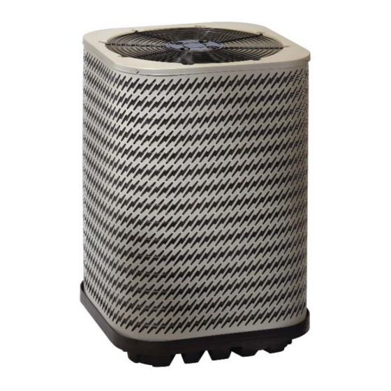
JS5BD SERIES
USER'S MANUAL / INSTALLATION INSTRUCTIONS
SPLIT SYSTEM AIR CONDITIONER - R-22
Please read this information thoroughly and become familiar with the capabilities and
use of your appliance before attempting to operate or maintain this unit. Keep this
literature where you have easy access to it in the future. If a problem occurs, check the
instructions and follow recommendations given. If these suggestions don't eliminate
the problem, call your servicing contractor.
The Installation Instructions are primarily intended to assist qualifi ed individuals
experienced in the proper installation of this appliance. Some local codes require licensed
installation/service personnel for this type of equipment. Please read all instructions
carefully before starting the installation.
IMPORTANT
DO NOT DESTROY. PLEASE READ CAREFULLY AND
KEEP IN A SAFE PLACE FOR FUTURE REFERENCE.
13 SEER
Advertisement
Table of Contents

Related Manuals for Nortek JS5BD


Summary of Contents for Nortek JS5BD
- Page 1 JS5BD SERIES 13 SEER USER’S MANUAL / INSTALLATION INSTRUCTIONS SPLIT SYSTEM AIR CONDITIONER - R-22 IMPORTANT Please read this information thoroughly and become familiar with the capabilities and use of your appliance before attempting to operate or maintain this unit. Keep this literature where you have easy access to it in the future.
-
Page 2: Table Of Contents
Figures & Tables ............10 Important Safety Information ........4 Refrigerant Charging Tables ........10 Air Conditioner Installation ........5 Table 5. JS5BD-018 (1.5 Ton Units) ....10 General Information ...........5 Table 6. JS5BD-018KB (2 Ton Units) ....10 Before You Install this Unit .........5 Table 7. -
Page 3: Important Safety Information
USER INFORMATION IMPORTANT SAFETY INFORMATION The continuous indoor blower operation can be obtained with the thermostat system mode set in any position, Safety markings are used frequently throughout this including OFF. manual to designate a degree or level of seriousness and should not be ignored. -
Page 4: Important Safety Information
DO NOT USE ANY PORTION OF WARNING: THE CHARGE FOR PURGING OR LEAK TESTING. Installation or servicing should only be performed by JS5BD Split System Air conditioners leave qualifi ed trained personnel thoroughly familiar with this the factory with a nitrogen holding charge. type equipment. -
Page 5: Air Conditioner Installation
• Survey the job site to determine the best location for General Information mounting the outdoor unit. See Figure 5 (page 12) for The JS5BD series air conditioner is designed only for unit dimensions. outdoor rooftop or ground level installations. This unit has •... -
Page 6: Connecting Refrigerant Tubing Between The Indoor & Outdoor Unit
Connecting Refrigerant Tubing Between the Indoor • It is proper installation practice and highly recommended & Outdoor Unit to install a fi lter drier when the system is open to the atmosphere. This includes, but is not limited to, CAUTION: replacing the evaporator and/or condenser of a system. -
Page 7: Grounding
• Optional equipment requiring connection to the power or control circuits must be wired in strict accordance of the NEC (ANSI/NFPA 70), applicable local codes, Table 2. Thermostat Wire Gauge and the instructions provided with the equipment. Grounding JS5BD-24K WARNING: Volts-Cycles-Phase 208/230-60-1 Total Amps 11.5... -
Page 8: Startup & Adjustments
Listen for any unusual noises. If unusual charging. sounds occur, determine the source of the noise and • JS5BD outdoor units with indoor coils not listed are correct as necessary. not recommended. Deviations from rated airfl ows or 3. Verify HI and LO refrigerant pressures. -
Page 9: Charging R-22 Units In Ac Mode With Outdoor Temperatures Above 55° F
Model Number Height Width Depth • Inspect the condensate drain and outdoor coil at the JS5BD- beginning of each cooling season. Remove any debris. Clean the outdoor coil and louvers as necessary using 23" 22 3/4" 22 3/4"... -
Page 10: Figures & Tables
Dis. Liq. Dis. Liq. Dis. Liq. Dis. Liq. Dis. Liq. Dis. Press. Temp. Press. Temp. Press. Temp. Press. Temp. Press. Temp. Press. Temp. Press. Temp. Press. Temp. Table 6. Charging Table for JS5BD-024KB Series (2 Ton Units with Microchannel Coil) - Page 11 Press. Temp. Press. Temp. Press. Temp. Press. Temp. Press. Temp. Press. Temp. Table 7. Charging Table for JS5BD-030KB Series (2.5 Ton Units with Microchannel Coil) OUTDOOR TEMPERATURE (° F) Suct. Press. Liq. Dis. Liq. Dis. Liq. Dis. Liq. Dis. Liq.
- Page 12 Press. Temp. Press. Temp. Press. Temp. Press. Temp. Press. Temp. Press. Temp. Press. Temp. Table 9. Charging Table for JS5BD-042 Series (3.5 Ton Units) OUTDOOR TEMPERATURE (° F) Suct. Press. Liq. Dis. Liq. Dis. Liq. Dis. Liq. Dis. Liq. Dis.
-
Page 13: Refrigerant Charging Charts
Press. Temp. Press. Temp. Press. Temp. Table 11. Charging Table for JS5BD-060 Series (5 Ton Units) TXV COOLING CHARGING CHARTS JS5BD-018 SERIES CHARGING CHART Remove refrigerant when above curve Add refrigerant when below curve Liquid Temperature (F) Figure 5. Charging Chart for 1.5 Ton Units... - Page 14 JS5BD-024KB SERIES CHARGING CHART Remove refrigerant when above curve Add refrigerant when below curve Liquid Temperature (F) Figure 6. Charging Chart for 2 Ton Units (with Microchannel Coil) JS5BD-030KB SERIES CHARGING CHART Remove refrigerant when above curve Add refrigerant when below curve Liquid Temperature (F) Figure 7.
- Page 15 JS5BD-036KB SERIES CHARGING CHART Remove refrigerant when above curve Add refrigerant when below curve Liquid Temperature (F) Figure 8. Charging Chart for 3 Ton Units (with Microchannel Coil) JS5BD-042 SERIES CHARGING CHART Remove refrigerant when above curve Add refrigerant when below curve Liquid Temperature (F) Figure 9.
- Page 16 JS5BD-048 SERIES CHARGING CHART Remove refrigerant when above curve Add refrigerant when below curve Liquid Temperature (F) Figure 10. Charging Chart for 4 Ton Units JS5BD-060 SERIES CHARGING CHART Remove refrigerant when above curve Add refrigerant when below curve Liquid Temperature (F)
- Page 17 24 VOLT FIELD CRANKCASE CONNECTIONS HEATER SEE NOTE 6 (OPTIONAL) ¢710570|¤ LEGEND: FIELD WIRING CC - Contactor Coil 710570B LOW VOLTAGE CCH - Crankcase Heater (Replaces 710570A) HIGH VOLTAGE HPS - High Pressure Switch 0109 Figure 12. JS5BD Wiring Diagram...
- Page 20 ¢709241§¤ Specifi cations & illustrations subject to change without notice or incurring obligations. O’ Fallon, MO | Printed in U.S.A. (08/10) 7092410 (Replaces 7092340)
Need help?
Do you have a question about the JS5BD and is the answer not in the manual?
Questions and answers