
Related Manuals for MSI MS-6566E


Summary of Contents for MSI MS-6566E
- Page 1 All manuals and user guides at all-guides.com 845E Max MICRO-STAR INTERNATIONAL MS-6566E (v1.X) ATX Mainboard Version 1.0 G52-MA00565...
- Page 2 All manuals and user guides at all-guides.com FCC-B Radio Frequency Interference Statement Notice 1 Notice 2 VOIR LA NOTICE D’INSTALLATION AVANT DE RACCORDER AU RESEAU. Micro-Star International MS-6566E Tested to comply with FCC Standard For Home or Office Use...
- Page 3 All manuals and user guides at all-guides.com Edition Copyright Notice MICRO-STAR INTERNATIONAL Trademarks ® ® ® ® ® ® ® Revision History Revision Revision History Date...
- Page 4 All manuals and user guides at all-guides.com Safety Instructions CAUTION:...
- Page 5 All manuals and user guides at all-guides.com CONTENTS Chapter 1. Getting Started ................ 1-1 Chapter 2. Hardware Setup ............... 2-1...
- Page 6 All manuals and user guides at all-guides.com Chapter 3. AMI BIOS Setup ..............3-1...
- Page 7 All manuals and user guides at all-guides.com Glossary ....................G-1...
-
Page 8: Getting Started
All manuals and user guides at all-guides.com Getting Started Chapter 1. Getting Started Getting Started Thank you for purchasing the MSI 845E Max (MS-6566E v1.X) ATX mainboard. The MSI 845E Max is based on Intel 845E & ICH4 chipsets for ®... -
Page 9: Mainboard Specification
All manuals and user guides at all-guides.com Chapter 1 Mainboard Specification ® ® Chipset ® ® ® Main Memory Slots On-Board IDE On-Board Peripherals... - Page 10 All manuals and user guides at all-guides.com Getting Started Audio (optional) Onboard Intel LAN (optional) BIOS Dimension Mounting Others...
-
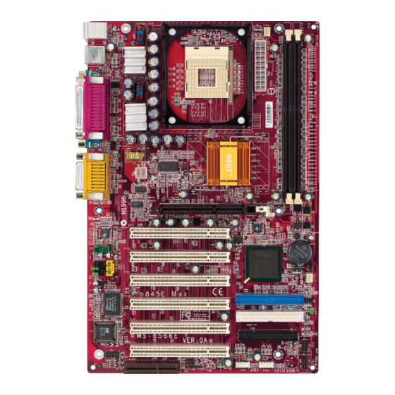
Page 11: Mainboard Layout
JAUD1 Intel ICH4 Chipset PCI Slot 3 SFAN1 JCD1 IDE 1 PCI Slot 4 Winbond W83627HF-AW JBAT1 IDE 2 PCI Slot 5 FDD1 BIOS PCI Slot 6 JFP2 JDB1 JUSB1 JUSB2 JIR1 JFP1 JWR1 845E Max (MS-6566E v1.X) ATX Mainboard... -
Page 12: Quick Components Guide
All manuals and user guides at all-guides.com Getting Started Quick Components Guide... -
Page 13: Msi Special Features
All manuals and user guides at all-guides.com Chapter 1 MSI Special Features Fuzzy Logic™ III Save Turbo Auto Turbo AGP Ratio Adjust CPU Vcore AGP Ratio Adjust CPU Vcore 1.850V 1.825V 1.775V 1.750V Features:... - Page 14 All manuals and user guides at all-guides.com Getting Started PC Alert™ III Note: Items shown on PC Alert III vary depending on your system’s status.
- Page 15 All manuals and user guides at all-guides.com Chapter 1 D-Bracket™ 2 (optional) D-Bracket™ 2 Green D-Bracket™ 2 Description Processor Initialization - This will show information regarding the processor (like brand name, system bus, etc...) Early Chipset Initialization Memory Detection Test - Testing onboard memory size.
- Page 16 All manuals and user guides at all-guides.com Getting Started Description D-Bracket™ 2 Processor Initialization - This will show information regarding the processor (like brand name, system bus, etc...) Testing RTC (Real Time Clock Initializing Video Interface - This will start detecting CPU clock, checking type of video onboard.
- Page 17 All manuals and user guides at all-guides.com Chapter 1 Live BIOS™/Live Driver™ l l l l l Live BIOS – Updates the BIOS online. l l l l l Live Driver – Updates the drivers online. l l l l l Live VGA BIOS – Updates the VGA BIOS online. l l l l l Live VGA Driver –...
- Page 18 All manuals and user guides at all-guides.com Getting Started Live Monitor™ l l l l l Auto Search – Searches for the BIOS/drivers version you need immediately. l l l l l View Last Result – Allows you to view the last search result if there is any. l l l l l Preference –...
-
Page 19: Hardware Setup
All manuals and user guides at all-guides.com Hardware Setup Chapter 2. Hardware Setup Hardware Setup TOPICS... -
Page 20: Central Processing Unit (Cpu)
All manuals and user guides at all-guides.com Chapter 2 Central Processing Unit: CPU ® ® make sure the CPU has a heat sink and a cooling fan attached on the top to prevent overheating. Open Lever Sliding Plate Gold Arrow Close Lever... - Page 21 All manuals and user guides at all-guides.com Hardware Setup retention mechanism...
- Page 22 All manuals and user guides at all-guides.com Chapter 2 fan power cable then Overclocking We do not guarantee the damages or risks caused by inadequate operation or beyond product specifications.
- Page 23 All manuals and user guides at all-guides.com Hardware Setup Memory...
- Page 24 All manuals and user guides at all-guides.com Chapter 2 Slot Momory Module Total Memory Slot 1 64MB, 128MB, 256MB, 64MB~1GB (Bank 0 & 1) 512MB, 1GB Slot 2 64MB, 128MB, 256MB, 64MB~1GB (Bank 2 & 3) 512MB, 1GB Maximum System Memory Supported 64MB~2GB notch Volt...
-
Page 25: Power Supply
All manuals and user guides at all-guides.com Hardware Setup Power Supply instant power on JW1 Pin Definition SIGNAL SIGNAL JPW1 Pin Definition SIGNAL... -
Page 26: Back Panel
All manuals and user guides at all-guides.com Chapter 2 Back Panel ® ® ® Pin Definition SIGNAL DESCRIPTION... - Page 27 All manuals and user guides at all-guides.com Hardware Setup ® ® ® Pin Definition SIGNAL DESCRIPTION USB Port Description SIGNAL DESCRIPTION...
- Page 28 All manuals and user guides at all-guides.com Chapter 2 Pin Definition SIGNAL DESCRIPTION Line Out Line In 1/8” Stereo Audio Connectors 2-10...
- Page 29 All manuals and user guides at all-guides.com Hardware Setup Pin Definition SIGNAL DESCRIPTION 2-11...
- Page 30 All manuals and user guides at all-guides.com Chapter 2 Signal Description Activity Indicators (RJ-45) 2-12...
- Page 31 All manuals and user guides at all-guides.com Hardware Setup Connectors FDD1 VCC5 IRTX IRRX 2-13...
- Page 32 All manuals and user guides at all-guides.com Chapter 2 IDE 1 IDE 2 IDE1 IDE2 2-14...
- Page 33 All manuals and user guides at all-guides.com Hardware Setup 2-15...
- Page 34 All manuals and user guides at all-guides.com Chapter 2 +12V SENSOR CFAN1 +12V SENSOR SFAN1 Note: 2-16...
- Page 35 All manuals and user guides at all-guides.com Hardware Setup ® PWSW JFP2 Pin Definition Signal Signal JFP1 Switch/LED Front Panel Electrical Connection SIGNAL DESCRIPTION 2-17...
- Page 36 All manuals and user guides at all-guides.com Chapter 2 ® Pin Definition SIGNAL DESCRIPTION Note: 2-18...
- Page 37 All manuals and user guides at all-guides.com Hardware Setup Connected to JDB1 Connected to JUSB1 2-19...
- Page 38 All manuals and user guides at all-guides.com Chapter 2 USB HDD digital cameras MP3 players printers mo- dems and the like ® JUSB1/JUSB2 Pin Definition Description Description 2-20...
- Page 39 All manuals and user guides at all-guides.com Hardware Setup To Attach the Optional USB 2.0 Ports: Connecting to JUSB2 (the USB connector in blue color) If no Bluetooth function is applied, remove the sticker to utilize this port. Note: ® 2-21...
- Page 40 All manuals and user guides at all-guides.com Chapter 2 Signal 2-22...
- Page 41 All manuals and user guides at all-guides.com Hardware Setup Jumpers Clear CMOS Keep CMOS 2-23...
- Page 42 All manuals and user guides at all-guides.com Chapter 2 Slots 2-24...
- Page 43 All manuals and user guides at all-guides.com Hardware Setup Attention! DO NOT use the following AGP cards which would result in failure to restart the system. The following list is subject to change without prior notice. Model AGP Chip ATI Xpert2000 3D RAGE 128VR ATI Rage Furry Maxx 3D RAGE 128 Pro...
- Page 44 All manuals and user guides at all-guides.com Chapter 2 Order 1 Order 2 Order 3 Order 4 PCI Slot 1 INT A# INT B# INT C# INT D# PCI Slot 2 INT B# INT C# INT D# INT A# PCI Slot 3 INT C# INT D# INT A#...
-
Page 45: Chapter 3. Bios Setup
All manuals and user guides at all-guides.com AMI BIOS Setup Chapter 3. BIOS Setup AMI BIOS Setup... -
Page 46: Entering Setup
All manuals and user guides at all-guides.com Chapter 3 Entering Setup DEL:Setup F11:Boot Menu F12:Network boot TAB:Logo Selecting the First Boot Device Select First Boot Device Floppy : 1st Floppy IDE-0 : IBM-DTLA-307038 CDROM : ATAPI CD-ROM DRIVE 40X M [Up/Dn] Select [RETURN] Boot [ESC] cancel... -
Page 47: Control Keys
All manuals and user guides at all-guides.com AMI BIOS Setup Control Keys <-> Move to the previous item Move to the next item <¯> Move to the item in the left hand <¬> <®> Move to the item in the right hand <Enter>... -
Page 48: The Main Menu
All manuals and user guides at all-guides.com Chapter 3 The Main Menu ®... - Page 49 All manuals and user guides at all-guides.com AMI BIOS Setup...
-
Page 50: Standard Cmos Features
All manuals and user guides at all-guides.com Chapter 3 Standard CMOS Features... - Page 51 All manuals and user guides at all-guides.com AMI BIOS Setup Note:...
-
Page 52: Advanced Bios Features
All manuals and user guides at all-guides.com Chapter 3 Advanced BIOS Features... - Page 53 All manuals and user guides at all-guides.com AMI BIOS Setup Note...
- Page 54 All manuals and user guides at all-guides.com Chapter 3 ® ® 3-10...
- Page 55 All manuals and user guides at all-guides.com AMI BIOS Setup 3-11...
-
Page 56: Advanced Chipset Features
All manuals and user guides at all-guides.com Chapter 3 Advanced Chipset Features Note: 3-12... - Page 57 All manuals and user guides at all-guides.com AMI BIOS Setup 3-13...
-
Page 58: Power Management Setup
All manuals and user guides at all-guides.com Chapter 3 Power Management Setup 3-14... - Page 59 All manuals and user guides at all-guides.com AMI BIOS Setup 3-15...
- Page 60 All manuals and user guides at all-guides.com Chapter 3 Note: Note 3-16...
- Page 61 All manuals and user guides at all-guides.com AMI BIOS Setup Note 1 Note 2 3-17...
-
Page 62: Pnp/Pci Configurations
All manuals and user guides at all-guides.com Chapter 3 PNP/PCI Configurations 3-18... - Page 63 All manuals and user guides at all-guides.com AMI BIOS Setup 3-19...
- Page 64 All manuals and user guides at all-guides.com Chapter 3 3-20...
-
Page 65: Integrated Peripherals
All manuals and user guides at all-guides.com AMI BIOS Setup Integrated Peripherals 3-21... - Page 66 All manuals and user guides at all-guides.com Chapter 3 3-22...
- Page 67 All manuals and user guides at all-guides.com AMI BIOS Setup 3-23...
-
Page 68: Pc Health Status
All manuals and user guides at all-guides.com Chapter 3 PC Health Status Note: 3-24... -
Page 69: Frequency/Voltage Control
All manuals and user guides at all-guides.com AMI BIOS Setup Frequency/Voltage Control 3-25... - Page 70 All manuals and user guides at all-guides.com Chapter 3 Note 1: Note 2: 3-26...
-
Page 71: Supervisor/User Password
All manuals and user guides at all-guides.com AMI BIOS Setup Supervisor/User Password About Supervisor Password & User Password: 3-27... -
Page 72: Load High Performance/Bios Setup Defaults
All manuals and user guides at all-guides.com Chapter 3 Load High Performance/BIOS Setup Defaults The option is for power or overclocking users only. Use of high performance defaults will tighten most timings to increase the sys- tem performance. Therefore, a high-end system configuration is a WARNING! must, which means you need high-quality VGA adapter, RAM and so on. - Page 73 All manuals and user guides at all-guides.com Glossary Glossary Glossary ACPI Advanced Configuration & Power Interface AGP Accelerated Graphics Port BIOS basic input/output system Cache Chipset...
- Page 74 All manuals and user guides at all-guides.com Glossary CMOS complementary metal-oxide semiconductor DIMM dual in-line memory module SIMM (single in-line memory module) DRAM Dynamic RAM Dynamic RAM (DRAM) Memory Technologies Peak Type First Used Clock Rate Bus* Width Volts Bandwidth FPM (60,70ns) 1990 25MHz...
- Page 75 All manuals and user guides at all-guides.com Glossary ECC Memory error correcting code memory IDE Integrated Drive Electronics IEEE 1394 FireWire iLink IrDA Infrared Data Association LAN local area network LED light emitting diode LPT line printer terminal...
- Page 76 All manuals and user guides at all-guides.com Glossary PCI Peripheral Component Interconnect PnP Plug and Play POST Power On Self Test PS/2 Port USB universal serial bus Virus...
Need help?
Do you have a question about the MS-6566E and is the answer not in the manual?
Questions and answers