Table of Contents
Advertisement
Quick Links
Advertisement
Table of Contents

Related Manuals for MSI 845PE Neo Series


Summary of Contents for MSI 845PE Neo Series
- Page 1 845PE Neo Series MS-6580 (v5.X) ATX Mainboard Version 5.0 G52-M6580XM...
-
Page 2: Fcc-B Radio Frequency Interference Statement
Manual Rev: 5.0 Release Date: December 2003 FCC-B Radio Frequency Interference Statement This equipment has been tested and found to comply with the limits for a class B digital device, pursuant to part 15 of the FCC rules. These limits are designed to provide reasonable protection against harmful interference when the equip- ment is operated in a commercial environment. -
Page 3: Copyright Notice
Alternatively, please try the following help resources for further guidance. Visit the MSI website for FAQ, technical guide, BIOS updates, driver updates, and other information: http://www.msi.com.tw/ Contact our technical staff at: support@msi.com.tw... -
Page 4: Safety Instructions
Safety Instructions Always read the safety instructions carefully. Keep this User’s Manual for future reference. Keep this equipment away from humidity. Lay this equipment on a reliable flat surface before setting it up. The openings on the enclosure are for air convection hence protects the equipment from overheating. -
Page 5: Table Of Contents
Technical Support ..................... iii Safety Instructions ...................iv Chapter 1. Getting Started ................1-1 Mainboard Specifications ............... 1-2 Mainboard Layout ................... 1-4 MSI Special Features................1-5 Color Management ................1-5 CoreCenter ..................1-6 Live Monitor ..................1-8 Live BIOS/Live Driver ............... 1-9 D-Bracket 2 (Optional) .............. - Page 6 ATX 20-Pin Power Connector: PWR1 ..........2-9 ATX 12V Power Connector: JPW1 ..........2-9 Back Panel ....................2-10 Keyboard Connector ..............2-10 Mouse Connector................2-11 USB Connectors ................2-11 RJ-45 LAN Jack (Optional) ............. 2-12 Serial Port Connector: COM A ............2-12 Parallel Port Connector ..............
- Page 7 The Main Menu ..................3-4 Standard CMOS Features ................ 3-6 Advanced BIOS Features ................ 3-8 Advanced Chipset Features ..............3-13 Power Management Features ..............3-16 PNP/PCI Configurations................ 3-20 Integrated Peripherals ................3-23 PC Health Status ..................3-26 Frequency/Voltage Control ..............3-27 Set Supervisor/User Password .............
-
Page 8: Chapter 1. Getting Started
Getting Started Chapter 1. Getting Started Getting Started Thank you for purchasing the 845PE Neo (MS-6580 v5.X) ® ATX mainboard. The 845PE Neo is based on Intel 845PE & ICH4 chipsets for optimal system efficiency. Designed to fit the ® advanced Intel P entium 4 Northwood/Prescott processor in the 478-pin package, the 845PE Neo delivers a high performance... -
Page 9: Mainboard Specifications
MS-6580 ATX Mainboard Mainboard Specifications † Supports Socket 478 for Intel ® Pentium 4 Northwood/Prescott processors † FSB 400/533/800MHz (over chipset spec.) † Supports up to 3.4 GHz and higher speed Chipsets † Intel ® 845PE chipsets - AGP 4x slot (1.5v only) - FSB 533/(800 MHz) (refer to Appendix B for details on FSB 800MHz ) - Support DDR 200/266/333/(400) DDR technology (refer to Appendix B for details on DDR400) - Page 10 Getting Started On-Board Peripherals † On-Board Peripherals include: - 1 floppy port supports 2 FDDs with 360K, 720K, 1.2M, 1.44M and 2.88Mbytes - 1 serial port connector COM A - 1 parallel port - 1 RJ-45 LAN Jack (Optional) - Audio ports in vertical stack - 1 rear coaxial SPDIF-Out - 6 USB ports (Rear * 4/ Front * 2) Audio...
-
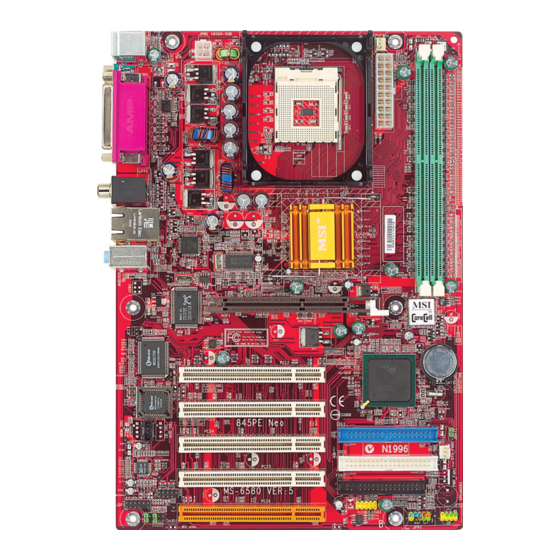
Page 11: Mainboard Layout
MS-6580 ATX Mainboard Mainboard Layout JPW1 CPUFAN1 Top : mouse Bottom: keyboard Top : Parallel Port Bottom: COMA ATX Power Supply T: SPDIF Out B: USB ports Intel T: LAN Jack B: USB ports 845PE Line-In chipset Line-Out AGP Slot Realtek RTL8100C JCI1... -
Page 12: Msi Special Features
Getting Started MSI Special Features Color Management MSI has a unified color management rule for some connectors on the mainboards, which helps you to install the memory modules, expansion cards and other peripherals devices more easily and conveniently. † Memory DDR DIMMs: light green †... -
Page 13: Corecenter
MS-6580 ATX Mainboard CoreCenter This all-in-one hardware console is advanced combination of the popular PC Alert and Fuzzy Logic. Including powerful function with hardware monitor, system alert and instinctive UI of overclocking, CoreCenter is just like your PC doctor that can detect, view and adjust the PC hardware and system status during real time operation. - Page 14 Getting Started Left-wing: Current system status In the left sub-menu, you can configure the settings of FSB, Vcore, Memory Voltage and AGP Voltage by clicking the radio button in front of each item and make it available (the radio button will be lighted as yellow when selected), use the “+”...
-
Page 15: Live Monitor
Live Monitor™ The Live Monitor™ is a tool used to schedule the search for the latest BIOS/drivers version on the MSI Web site. To use the function, you need to install the “MSI Live Update 3” application. After installation, the “MSI Live Monitor” icon (as shown on the right) will appear on the screen. -
Page 16: Live Bios/Live Driver
Live Update 3” icon (as shown on the right) will appear on the screen. Double click the “MSI Live Update 3” icon, and the following screen will appear: Five buttons are placed on the left column of the screen. Click the desired button to start the update process. -
Page 17: D-Bracket 2 (Optional)
MS-6580 ATX Mainboard D-Bracket™ 2 (Optional) D-Bracket™ 2 is an external USB bracket integrating four Diagnostic LEDs, which use graphic signal display to help users understand their system. The LEDs provide up to 16 combinations of signals to debug the system. The 4 LEDs can debug all problems that fail the system, such as VGA, RAM or other failures. - Page 18 Getting Started D-Bracket Description Processor Initialization - This will show information regarding the processor (like brand name, system bus, etc… ) Testing RTC (Real Time Clock) Initializing Video Interface - This will start detecting CPU clock, checking type of video onboard.
-
Page 19: Core Cell Chip
MS-6580 ATX Mainboard Core Cell Chip By diagnosing the current system util ization, the CoreCell™ Chip automatically tunes your motherboard to the optimal state, leading to less noise, longer duration, more power- saving and higher performance. Features of CoreCell™ Speedster -- Advanced O.C. -
Page 20: S-Bracket (Optional)
SPDIF jack (coaxial) SPDIF jack (optical) Analog Line-Out jacks CPU Thermal Protection Aimed to prevent the CPU from overheating, MSI has developed a CPU ® Thermal Protection mechanism for Intel CPU platform. This CPU Thermal Protection mechanism works on a thermal signal sensor. If the mechanism senses an abnormal temperature rise, it will automatically shut down the system and the CPU temperature will then drop down and resume normal. -
Page 21: Round Cable (Optional)
MS-6580 ATX Mainboard Round Cable (Optional) Round cable is an enhanced cable for PCI IDE and Ultra DMA controller. It has the following benefits: † Data transfer rate started by 133MB/s † Backward compatibility (ATA33/66/100/133) † Higher performance than traditional Flat cable (data rate) †... -
Page 22: Chapter 2. Hardware Setup
Hardware Setup Chapter 2. Hardware Setup Hardware Setup This chapter tells you how to install the CPU, memory modules, and expansion cards, as well as how to setup the jump- ers on the mainboard. Also, it provides the instructions on con- necting the peripheral devices, such as the mouse, keyboard, etc. -
Page 23: Quick Components Guide
MS-6580 ATX Mainboard Quick Components Guide CP U, p.2-3 CP UFAN1, p.2 -1 5 JPW 1, p.2-9 DDR DIMMs, p.2-7 PWR1, p.2-9 Back P anel I/O, p.2-10 JCI1, p.2-20 IDE1 & IDE2, p.2-16 CD_IN1, p.2 -2 0 JBAT1, p.2-22 SYS_FAN1, p.2 -15 FDD1, p.2-15 JDB1, p.2-21 JSP 1, p.2-19... -
Page 24: Central Processing Unit: Cpu
CPU core speed Host Clock x Core/Bus ratio 100MHz x 14 1.4 GHz MSI Reminds You... Overheating Overheating will seriously damage the CPU and system, al- ways make sure the cooling fan can work properly to protect the CPU from overheating. -
Page 25: Cpu Installation Procedures For Socket 478
MS-6580 ATX Mainboard CPU Installation Procedures for Socket 478 Please turn off the power and unplug the power cord before Open Lever installing the CPU. Pull the lever sideways away Sliding 90 degree Plate from the socket. Make sure to raise the lever up to a 90- degree angle. -
Page 26: Installing The Cpu Fan
Hardware Setup Installing the CPU Fan As processor technology pushes to faster speeds and higher performance, thermal management becomes increasingly important. To dissipate heat, you need to attach the CPU cooling fan and heatsink on top of the CPU. Follow the instructions below to install the Heatsink/Fan: Locate the CPU and its retention Position the heatsink onto the reten-... - Page 27 MS-6580 ATX Mainboard Connect the fan power cable from the mounted fan to the 3-pin fan power connector on the board. fan power cable NOTES...
-
Page 28: Memory
Hardware Setup Memory The mainboard provides 2 slots for 184-pin DDR SDRAM DIMM (Double In-Line Memory Module) modules and supports the memory size up to 2GB. You can install PC3200/DDR400, PC2700/DDR333, PC2100/ DDR266 or PC1600/DDR200 modules on the DDR DIMM slots (DDR 1~2). For more informaton on DDR400, please refer to Appendix B. -
Page 29: Dimm Module Combination
3. The plastic clip at each side of the DIMM slot will automatically close. Notch Volt MSI Reminds You... You can barely see the golden finger if the module is properly inserted in the socket. -
Page 30: Power Supply
Hardware Setup Power Supply The mainboard supports ATX power supply for the power system. Be- fore inserting the power supply connector, always make sure that all compo- nents are installed properly to ensure that no damage will be caused. ATX 20-Pin Power Connector: PWR1 This connector allows you to connect to an ATX power supply. -
Page 31: Back Panel
MS-6580 ATX Mainboard Back Panel The back panel provides the following connectors: Parallel Mouse SPDIF-Out L-in L-out COM A Keyboard Keyboard Connector ® The mainboard provides a standard PS/2 keyboard mini DIN connec- ® ® tor for attaching a PS/2 keyboard. -
Page 32: Mouse Connector
Hardware Setup Mouse Connector ® The mainboard provides a standard PS/2 mouse mini DIN connector ® ® for attaching a PS/2 mouse. You can plug a PS/2 mouse directly into this connector. The connector location and pin assignments are as follows: Pin Definition SIGNAL DESCRIPTION... -
Page 33: Lan Jack (Optional)
MS-6580 ATX Mainboard RJ-45 LAN Jack (Optional) The mainboard provides a RJ-45 connector that allows your computer to be connected to a network environment. Signal Description Activity TD P Trans mit differenti al pair TD N Trans mit differenti al pair Indicators Receive differential pair Not used... -
Page 34: Parallel Port Connector
Hardware Setup Parallel Port Connector The mainboard provides a 25-pin female centronic connector as LPT. A parallel port is a standard printer port that supports Enhanced Parallel Port (EPP) and Extended Capabilities Parallel Port (ECP) mode. Pin Definition SIGNAL DESCRIPTION STROBE Strobe D ATA0... -
Page 35: Audio Port Connectors
1/8” Stereo Audio Connectors Line Out Mic In SPDIF-Out Coaxial MSI Reminds You... For advanced audio application, Realtek ALC655 audio chip is provided as an option to offer support for 6-channel audio operation and can turn rear audio connectors from 2-channel to 4-/6-channel audio. -
Page 36: Connectors, Jumpers And Slots
CPU fan control. S E NS O R + 12 V + 12 V S E NS O R SYS_FAN1 CPUFAN1 MSI Reminds You... Always consult the vendors for proper CPU cooling fan. 2-15... -
Page 37: Hard Disk Connectors: Ide1 & Ide2
IDE2 (Secondary IDE Connector) IDE2 can also connect a Master and a Slave drive. MSI Reminds You... If you install two hard disks on cable, you must configure the second drive to Slave mode by setting its jumper. Refer to the hard disk documentation supplied by hard disk vendors for jumper setting instructions. -
Page 38: Front Panel Audio Connector: Jaud1
Left ch annel audio s ignal to fron t panel AUD _RET_L Left ch annel audio signal return from front panel MSI Reminds You... If you don’t want to connect to the front audio header, pins 5 & 6, 9 & 10 have to be jumpered in order to have signal output directed to the rear audio ports. -
Page 39: Front Panel Connectors: Jfp1 & Jfp2
MS-6580 ATX Mainboard Front Panel Connectors: JFP1 & JFP2 The mainboard provides two front panel connectors for establishing elec- trical connection to the front panel switches and LEDs. JFP1 is compliant ® with Intel Front Panel I/O Connectivity Design Guide. Reset H D D Sw itch... -
Page 40: S-Bracket Connector: Jsp1
Hardware Setup S-Bracket Connector: JSP1 The connector allows you to connect a S-Bracket for Sony & Philips Digital Interface (SPDIF). The S-Bracket offers 2 SPDIF jacks for digital audio transmission (one for optical fiber connection and the other for coaxial), and 2 analog Line-Out jacks for 4-channel audio output. -
Page 41: Front Usb Connector: Jusb1
MS-6580 ATX Mainboard Front USB Connector: JUSB1 The mainboard provides one USB2.0 pinheader for users to connect to ® optional USB2.0 ports. The pinheader is compliant to Intel I/O Connectivity Design Guide. USB 2.0 technology increases data transfer rate up to a maximum through- put of 480Mbps, which is 40 times faster than USB 1.1, and is ideal for connect- ing high-speed USB interface peripherals such as USB HDD, digital cameras, MP3 players, printers, modems and the like. -
Page 42: D-Bracket 2 Connector: Jdb1
Hardware Setup D-Bracket™ 2 Connector: JDB1 The mainboard comes with a JDB1 connector for you to connect to D- Bracket™ 2. D-Bracket™ 2 is a USB Bracket that supports both USB1.1 & 2.0 spec. It integrates four LEDs and allows users to identify system problem through 16 various combinations of LED signals. -
Page 43: Clear Cmos Jumper: Jbat1
JBAT1 Kee p CMOS Cle ar CMOS MSI Reminds You... You can clear CMOS by shorting 2-3 pin while the system is off. Then return to 1-2 pin position. Avoid clearing the CMOS while the system is on; it will damage the mainboard. -
Page 44: Pci Interrupt Request Routing
Hardware Setup PCI Interrupt Request Routing The IRQ, abbreviation of interrupt request line and pronounced I-R-Q, are hardware lines over which devices can send interrupt signals to the microprocessor. The “AGP/PCI/LAN” IRQ pins are typically connected to the PCI bus INT A# ~ INT F# pins as follows: Order1 Order2 Order3... -
Page 45: Chapter 3. Bios Setup
BIOS Setup Chapter 3. BIOS Setup BIOS Setup This chapter provides information on the BIOS Setup program and allows you to configure the system for optimum use. You may need to run the Setup program when: ² An error message appears on the screen during the system booting up, and requests you to run SETUP. -
Page 46: Entering Setup
MS-6580 ATX Mainboard Entering Setup Power on the computer and the system will start POST (Power On Self Test) process. When the message below appears on the screen, press <DEL> key to enter Setup. DEL:Setup F11:Boot Menu F12:Network boot TAB:Logo If the message disappears before you respond and you still wish to enter Setup, restart the system by turning it OFF and On or pressing the RESET button. -
Page 47: Control Keys
BIOS Setup Control Keys < > Move to the previous item < > Move to the next item < > Move to the item on the left-hand side < > Move to the item on the right-hand side <Enter> Select the item <Esc>... -
Page 48: The Main Menu
MS-6580 ATX Mainboard The Main Menu Once you enter AMIBIOS NEW SETUP UTILITY, the Main Menu will ap- pear on the screen. The Main Menu displays twelve configurable functions and two exit choices. Use arrow keys to move among the items and press <Enter>... - Page 49 BIOS Setup PNP/PCI Configurations This entry appears if your system supports PnP/PCI. Integrated Peripherals Use this menu to specify your settings for integrated peripherals. PC Health Status This entry shows your PC health status. Frequency/Voltage Control Use this menu to specify your settings for frequency/voltage control. Set Supervisor Password Use this menu to set Supervisor Password.
-
Page 50: Standard Cmos Features
MS-6580 ATX Mainboard Standard CMOS Features The items inside STANDARD CMOS FEATURES menu are divided into 9 categories. Each category includes none, one or more setup items. Use the arrow keys to highlight the item you want to modify and use the <PgUp> or <PgDn>... - Page 51 When Enabled, BIOS will issue a virus warning message and beep if a write to the boot sector or the partition table of the HDD is attempted. Setting options: Disabled and Enabled. MSI Reminds You... This feature only protects the boot sector, not the whole hard disk.
-
Page 52: Advanced Bios Features
MS-6580 ATX Mainboard Advanced BIOS Features Quick Boot Setting the item to Enabled allows the system to boot within 5 seconds since it will skip some check items. Available options: Enabled, Disabled. Full Screen Logo Show This item enables you to show the company logo on the bootup screen. Set- tings are: Silent Shows a still image (logo) on the full screen at boot. - Page 53 BIOS Setup 1st/2nd/3rd Boot Device The items allow you to set the sequence of boot devices where AMIBIOS attempts to load the operating system. The settings are: IDE-0 The system will boot from the first HDD. IDE-1 The system will boot from the second HDD. IDE-2 The system will boot from the third HDD.
- Page 54 MS-6580 ATX Mainboard MSI Reminds You... 1. Available settings for “1st/2nd/3rd Boot Device” vary de- pending on the bootable devices you have installed. For example, if you did not install a floppy drive, the setting “Floppy” does not show up.
- Page 55 This field is used to enable or disable the Hyper Threading function. Setting to Enabled will increase the system performance. Settings: Enabled, Disabled. MSI Reminds You... Enabling the functionality of Hyper-Threading Technology for your computer system requires ALL of the following platform Components: ®...
- Page 56 MS-6580 ATX Mainboard version supported by your operating system. To find out which version to use, consult the vendor of your operating system. Settings: 1.4, 1.1. CPU L1 & L2 Cache Cache memory is additional memory that is much faster than conventional DRAM (system memory).
-
Page 57: Advanced Chipset Features
BIOS Setup Advanced Chipset Features MSI Reminds You... Change these settings only if you are familiar with the chipset. DRAM Timing Setting Press <Enter> and the following sub-menu appears. 3-13... - Page 58 MS-6580 ATX Mainboard DRAM Frequency Use this field to configure the clock frequency of the installed DRAM. Settings are: SPD, 200MHz, 266MHz, 333MHz, Auto. Configure SDRAM Timing by SPD Selects whether DRAM timing is controlled by the SPD (Serial Presence Detect) EEPROM on the DRAM module.
- Page 59 BIOS Setup of the next memory location to be accessed after the first address is accessed. To use the feature, you need to define the burst length, which is the actual length of burst plus the starting address and allows internal address counter to properly generate the next memory location.
-
Page 60: Power Management Features
MS-6580 ATX Mainboard Power Management Features MSI Reminds You... S3-related functions described in this section are available only when your BIOS supports S3 sleep mode. IPCA Function This item is to activate the ACPI (Advanced Configuration and Power Man- agement Interface) function. If your operating system is ACPI-aware, such as Windows 98SE/2000/ME, select Yes. - Page 61 BIOS Setup S3/STR The S3 sleep mode is a lower power state where the in formation of system configuration and open applications/ files is saved to main memory that remains powered while most other hardware components turn off to save energy.
- Page 62 MS-6580 ATX Mainboard Set Monitor Events Press <Enter> and the following sub-menu appears. FDC/LPT/COM Ports, Primary/Secondary master/Slave IDE These items specify if the BIOS will monitor the activity of the specified hardware peripheral or component. If set to Monitor, any activity de- tected on the specified hardware peripheral or component will wake up the system or prevent the system from entering the power saving modes.
- Page 63 Alarm Minute 00 ~ 59 Alarm Second 00 ~ 59 MSI Reminds You... If you have changed this setting, you must let the system boot up until it enters the operating system, before this function will work. USB Wakeup From S3 This item allows the activity of the USB device to wake up the system from S3 (Suspend to RAM) sleep state.
-
Page 64: Pnp/Pci Configurations
MS-6580 ATX Mainboard PNP/PCI Configurations This section describes configuring the PCI bus system and PnP (Plug & Play) feature. PCI, or Peripheral Component Interconnect, is a system which al- lows I/O devices to operate at speeds nearing the speed the CPU itself uses when communicating with its special components. - Page 65 BIOS Setup tions for a longer time and thus improve the effective PCI bandwidth. For better PCI performance, you should set the item to higher values. Settings range from 32 to 248 at a 32 increment. Init. Graphics Adaptor Priority This setting specifies which VGA card is your primary graphics adapter.
- Page 66 MS-6580 ATX Mainboard IRQ 3/4/5/7/9/10/11/14/15 These items specify the bus where the specified IRQ line is used. The settings determine if AMIBIOS should remove an IRQ from the pool of available IRQs passed to devices that are configurable by the system BIOS.
-
Page 67: Integrated Peripherals
BIOS Setup Integrated Peripherals USB Controller This setting is used to enable/disable the onboard USB controllers. Setting options: Enabled, Disabled. USB Legacy Support Set to All Device if you need to use a USB device in the operating system that does not support or have any USB driver installed, such as DOS and SCO Unix. - Page 68 MS-6580 ATX Mainboard Load OnBoard LAN BIOS This feature gives you the option to load the onboard LAN BIOS or not. Setting options: Enabled, Disabled. AC’97 Audio Auto allows the mainboard to detect whether an audio device is used. If an audio device is detected, the onboard AC’97 (Audio Codec’97) controller will be enabled;...
- Page 69 BIOS Setup OnBoard Parallel Port This field specifies the base I/O port address of the onboard parallel port. Selecting Auto allows AMIBIOS to automatically determine the correct base I/O port address. Settings: Auto, 378, 278, 3BC, Disabled. Parallel Port Mode This item selects the operation mode for the onboard parallel port: ECP, Normal, Bi-Dir or EPP.
-
Page 70: Pc Health Status
MS-6580 ATX Mainboard PC Health Status This section shows the status of your CPU, fan, overall system status, etc. Monitor function is available only if there is hardware monitoring mechanism onboard. Chassis Intrusion The field enables or disables the feature of recording the chassis intrusion status and issuing a warning message if the chassis is once opened. -
Page 71: Frequency/Voltage Control
Use this menu to specify your settings for frequency/voltage control. Dynamic OverClocking Dynamic Overclocking Technology is the automatic overclocking function, included in the MSI ’s newly developed CoreCell Technology. It is designed to detect the load balance of CPU while running programs, and to adjust the best CPU frequency automatically. - Page 72 CPU frequency by 5% Colonel increase the CPU frequency by 7% General increase the CPU frequency by 10% MSI Reminds You... Dynamic OverClocking is an advanced overclocking function. Any damage or risk resulted from impropriety or overclocking is not guaranteed. Spread Spectrum When the motherboard clock generator pulses, the extreme values (spikes) of the pulses creates EMI (Electromagnetic Interference).
- Page 73 BIOS Setup MSI Reminds You... Changing CPU Ratio/Vcore could result in the instability of the system; therefore, it is NOT recommended to change the default setting for long-term usage. DDR/AGP Power Voltage Adjusting the DDR/AGP voltage can increase the DDR/AGP speed. Any changes made to these settings may cause a stability issue, so changing the DDR/AGP voltage for long-term purpose is NOT recommended.
-
Page 74: Set Supervisor/User Password
BIOS FEATURES menu. If the PASSWORD CHECK option is set to Always, the password is required both at boot and at entry to Setup. If set to Setup, password prompt only occurs when you try to enter Setup. MSI Reminds You... About Supervisor Password & User Password: Supervisor password: Can enter and change the settings of the setup menu. -
Page 75: Load High Performance/Bios Setup Defaults
Pressing ‘Enter’ loads the default BIOS values that enable the best system performance but may lead to a stability issue. MSI Reminds You... The option is for power or overclocking users only. Use of high performance defaults will tighten most timings to increase the system performance. -
Page 76: Appendix A: Using 2-, 4- Or 6-Channel Audio Function
Using 2-, 4- or 6-Channel Audio Function Appendix A: Using 2-, 4- & 6-Channel Audio Function The mainboard is equipped with Realtek ALC655 chip, which provides support for 6-channel audio output, including 2 Front, 2 Rear, 1 Center and 1 Subwoofer channel. - Page 77 1. Insert the companion CD into the CD-ROM drive. The setup screen will automatically appear. 2. Click Realtek AC97 Audio Drivers. Click here MSI Reminds You... The AC97 Audio Configuration software utility is under continuous update to enhance audio applications. Hence, the...
- Page 78 Using 2-, 4- or 6-Channel Audio Function 3. Click Next to install the AC’97 Audio software. Cl i ck here 4. Click Finish to restart the system. Select thi s option Cl i ck here...
- Page 79 MS-6580 ATX Mainboard Software Configuration After installing the audio driver, you are able to use the 4-/6-channel audio feature now. Click the audio icon from the window tray at the lower- right corner of the screen to activate the AC97 Audio Configuration. Sound Effect Here you can select a sound effect you like from the Environment list.
- Page 80 Using 2-, 4- or 6-Channel Audio Function Here it provides the Karaoke function which will automatically remove human voice (lyrics) and leave melody for you to sing the song. Note that this function applies only for 2-channel audio operation. Just check the Voice Cancellation box and then click OK to activate the Karaoke function.
- Page 81 MS-6580 ATX Mainboard Equalizer Here you regulate each equalizer for current playing digital sound sources. You may choose the provided sound effects, and the equalizer will adjust automatically. If you like, you may also load an equalizer setting or make an new equalizer setting to save as an new one by using the buttons Load and Save.
- Page 82 Using 2-, 4- or 6-Channel Audio Function Speaker Configuration In this tab, you can easily configure your multi-channel audio function and speakers. 1. Select the audio configuration below which is identical to the audio jack on your mainboard. Option 1 is 6CH+ S/PDIF (Coaxial) without S-Bracket.
- Page 83 MS-6580 ATX Mainboard 2. Select a desired multi-channel operation from Number of Speakers. a. Headphone for the common headphone b. 2-Channel Mode for Stereo-Speaker Output c. 4-Channel Mode for 4-Speaker Output d. 6-Channel Mode for 5.1-Speaker Output 3. Here it shows the multi-channel setting for the audio jack. Please connect your speakers to the correct phone jack in accordance with the setting displayed here.
- Page 84 Using 2-, 4- or 6-Channel Audio Function Speaker Test You can use this tab to test each connected speaker to ensure if 4- or 6- channel audio operation works properly. If any speaker fails to make sound, then check whether the cable is inserted firmly to the connector or replace the bad speakers with good ones.
- Page 85 MS-6580 ATX Mainboard MSI Reminds You... 1. 6 speakers appear on the “Speaker Test” tab only when you select “6-Channel Mode” in the “Number of Speakers” col- umn in “Speaker Configuration” tab. If you select “4-Chan- nel Mode”, only 4 speakers appear on the window.
- Page 86 Using 2-, 4- or 6-Channel Audio Function HRTF Demo In this tab you may adjust your HRTF (Head Related Transfer Functions) 3D positional audio before playing 3D audio applications like gaming. You may also select different environment to choose the most suitable environment you like.
- Page 87 MS-6580 ATX Mainboard General In this tab it provides some information about the AC97 Audio Configu- ration utility, including Audio Driver Version, DirectX Version, Audio Control- ler & AC97 Codec. You may also select the language of this utility by choosing from the Language list.
- Page 88 Using 2-, 4- or 6-Channel Audio Function Using 2-, 4- & 6- Channel Audio Function Option 1: 6CH+SPDIF (coaxial) without S-Bracket Connecting the Speakers When you have set the Multi-Channel Audio Function mode properly in the software utility, connect your speakers to the correct phone jacks in accordance with the setting in software utility.
- Page 89 MS-6580 ATX Mainboard n 4-Channel Mode for 4-Speaker Output The audio jacks on the back panel always provide 2-channel analog audio output function, however these audio jacks can be transformed to 4- or 6- channel analog audio jacks by selecting the corresponding multi-channel operation from No.
- Page 90 Out function when 6-Channel Mode for 6-Speaker Output is selected. MSI Reminds You... If the audio signals coming from the Center and Subwoofer speaker are swapped when you play video or music on the computer, a converter may be required to exchange center and subwoofer audio signals.
- Page 91 MS-6580 ATX Mainboard Option 2: 6CH+SPDIF (coaxial) with S-Bracket S-Bracket is an optional accessory. It gives access to analog and digital audio output by integrating both SPDIF (Sony & Philips Digital Interface) and analog LINE OUT connectors. To use the S-Bracket, you should select correct setting in the software utility.
- Page 92 Using 2-, 4- or 6-Channel Audio Function 4-Channel Analog Audio Output Line In Line Out (Front channels) Optical SPDIF jack Coaxial SPDIF jack Line Out (Center and Subwoofer channels, but no function in this mode) Line Out (Rear channels) Coaxial SPDIF jack Back Panel S-Bracket A-17...
- Page 93 MS-6580 ATX Mainboard 6-Channel Analog Audio Output Line In Line Out (Front channels) Optical SPDIF jack Coaxial SPDIF jack Line Out (Center and Subwoofer channels) Line Out (Rear channels) Coaxial SPDIF jack Back Panel S-Bracket A-18...
- Page 94 Using 2-, 4- or 6-Channel Audio Function Digital Audio Output (2-Channel only) For digital audio output, use the SPDIF (Sony & Philips Digital Interface) connectors supplied by S-Bracket. First, connect the SPDIF speakers to the appropriate SPDIF jack, and then select the audio channel you desire through the control panel of speakers.
-
Page 95: Appendix B: The Explanation For Overspecification And Overclocking On Intel
The explanation for overspecification and overclocking Appendix B: The explanation for overspecification and ® overclocking on Intel 845PE chipset ® The default specification of Intel 845PE chipset is only able to support FSB 400/533MHz CPU and DDR 266/333 DRAM technology. However, we have spent engineering efforts to allow the overspecification and overclocking of 845PE Max under certain conditions. - Page 96 MS-6580 ATX Mainboard 2. Configure BIOS settings You also need to configure BIOS settings for overclocking. A. In the “Advanced Chipset Features”, go to the sub-menu “DRAM Timing Settings” and set the “DRAM Frequence” to “Auto”. B. In the “Frequency/Voltage Control”, set “CPU FSB Clock (MHz)” as 200, which will make CPU FSB runs at 800 MHz.
- Page 97 The explanation for overspecification and overclocking 3. System configuration and DDR 400/PC 3200 Qualified Memory Test List When using DDR400 memory modules, a maximum of 2 DIMMs are recommended. Please refer to the system configuration and DDR400/PC3200 DIMMs listed below for overclocking. Table 1: System Configuration System Configuration Manufacturer...
- Page 98 MS-6580 ATX Mainboard Table 2: DDR400/PC3200 Memory Test List Model Size Memory Slot Memory Bandwidth R.S.T Benchmark √ √ Infineon HYS64D16301GU-5-B 128MB √ (Infineon HYB25D256160BT-5) √ √ Nanya NT128D64SH4B1G-5 128MB √ (Nanya NT5DS16M16BT-5) √ √ Nanya NT128D64SH4B1G-5T 128MB √ (NT5DS16M16BT-5T) Model Size Memory Slot...
- Page 99 The explanation for overspecification and overclocking Model Size Memory Slot Memory Bandwidth R.S.T Benchmark Apacer 77.10736.583 512MB √ (Winbond W942508BH-5) √ √ AG64L64T8SQC4S 512MB √ (SEC K4H560838E-TCCC) √ √ CORSAIR CMX512-3500C2PT XMS3502 V1.1 512MB √ √ √ Crucial/Micron BG111DB.FB 512MB √...
- Page 100 MS-6580 ATX Mainboard Model Size Memory Slot Memory Bandwidth R.S.T Benchmark √ √ Siemens SDU06464H1B22IN-50 512MB √ (Infineon HYB25D256800BT-5B) √ √ Transcend TS64MLD64V4F3 512MB √ (SEC K4H560838D-TCCC) Winbond W9451GCDB-5 512MB √ (WinBond W942508CH-5) [ - ] : Not Support...
Need help?
Do you have a question about the 845PE Neo Series and is the answer not in the manual?
Questions and answers