Table of Contents
Advertisement
Available languages
Available languages
FCC-B Radio Frequency Interference Statement
This equipment has been tested and found to comply with the limits for a class B digital device, pursuant to part 15 of
the FCC rules. These limits are designed to provide reasonable protection against harmful interference when the
equipment is operated in a commercial environment. This equipment generates, uses and can radiate radio frequency
energy and, if not installed and used in accordance with the instruction manual, may cause harmful interference to
radio communications. Operation of this equipment in a residential area is likely to cause harmful interference, in
which case the user will be required to correct the interference at his own expense.
Notice 1
The changes or modifications not expressly approved by the party responsible for compliance could void the user's
authority to operate the equipment.
Notice 2
Shielded interface cables and A.C. power cord, if any, must be used in order to comply with the emission limits.
VOIR LA NOTICE D'NSTALLATION AVANT DE RACCORDER AU RESEAU.
This device complies with Part 15 of the FCC Rules. Operation is subject to the following two conditions:
(1) this device may not cause harmful interference, and
(2) this device must accept any interference received, including interference that may cause undesired operation
Micro-Star International
MS-7061
G52-M7061X3
i
Advertisement
Table of Contents

Related Manuals for MSI KM3M-V Series


Summary of Contents for MSI KM3M-V Series
- Page 1 FCC-B Radio Frequency Interference Statement This equipment has been tested and found to comply with the limits for a class B digital device, pursuant to part 15 of the FCC rules. These limits are designed to provide reasonable protection against harmful interference when the equipment is operated in a commercial environment.
-
Page 2: Copyright Notice
Copyright Notice The material in this document is the intellectual property of MICRO-STAR INTERNATIONAL. We take every care in the preparation of this document, but no guarantee is given as to the correctness of its contents. Our products are under continual improvement and we reserve the right to make changes without notice. Trademarks All trademarks are the properties of their respective owners. -
Page 3: Safety Instructions
Safety Instructions 1. Always read the safety instructions carefully. 2. Keep this User Manual for future reference. 3. Keep this equipment away from humidity. 4. Lay this equipment on a reliable flat surface before setting it up. 5. The openings on the enclosure are for air convection hence protects the equipment from overheating. Do not cover the openings. - Page 4 Table of Content English...1 Deutsch...15 Français...31 简体中文 ...45 繁體中文 ...59 Nederlands ...71 日本語...85...
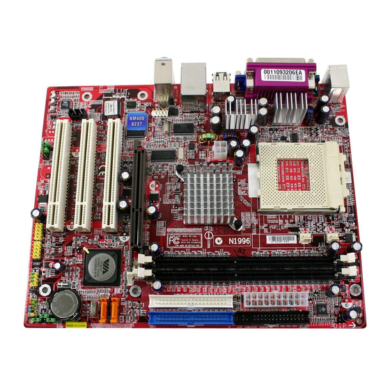
- Page 5 Introduction Thank you for choosing the KM4M-V/KM4AM-V/KM3M-V Series (MS-7061 v1.X) micro ATX mainboard. The KM4M-V/KM4AM-V/KM3M-V Series is based on VIA ® KM400/KM400A/KM266 Pro & VT8237 chipsets for optimal system efficiency. Designed to fit the advanced AMD ® Athlon XP/Duron processors in 462 pin package, the KM4M-V/KM4AM-V/KM3M-V Series delivers a high performance and professional desktop platform solution.
-
Page 6: Specifications
! Supports AMD ® Athlon ! Supports from 1100MHz up to 3000+ or above @ 266/333 MHz. (For the latest information about CPU, please visit http://www.msi.com.tw/program/products/mainboard/mbd/pro_mbd_cpu_support.php ) Chipset ! VIA ® KM266 Pro/KM400/KM400A chipset - FSB @ 266/333 MHz. (for KM266 Pro & KM400 ); FSB @ 266/333/400 MHz. (for KM400A only). - Page 7 - 2 SATA connectors (for KM400/KM400A only) - 8 USB 2.0 ports (Rear * 4/ Front * 4). - 3 audio (Line-In/Line-Out/Mic) ports. - COM2 on board with pin header (Intel pin-define). Audio - VIA1617A codec. - 5.1 channel AC’97 software Audio. - VIA VT8237 integrated MAC + VIA 6103 PHY.
-
Page 8: Rear Panel
If you do not find the heat sink and cooling fan, contact your dealer to purchase and install them before turning on the computer. (For the latest information about CPU, please visit http://www.msi.com.tw/program/products/mainboard/mbd/pro_mbd_cpu_support.php ) Example of CPU Core Speed Derivation Procedure... -
Page 9: Memory Speed/Cpu Fsb Support Matrix
Memory Speed/CPU FSB Support Matrix Memory 266 MHz 333 MHz 400 MHz (For KM400A only) CPU Installation Procedures for Socket 462 Please turn off the power and unplug the power cord before installing the CPU. Pull the lever sideways away from the socket. Make sure to raise the lever up to a 90-degree angle. - Page 10 MSI Reminds You... Overheating… Overheating will seriously damage the CPU and system, always make sure the cooling fan can work properly to protect the CPU from overheating. Replacing the CPU… While replacing the CPU, always turn off the ATX power supply or unplug the power supply’s power cord from grounded outlet first to ensure the safety of CPU.
-
Page 11: Chassis Intrusion Switch Connector: Jci1 (Optional)
Power Supply The mainboard supports ATX power supply for the power system. Before inserting the power supply connector, always make sure that all components are installed properly to ensure that no damage will be caused. A 300W or above power supply is suggested. ATX 20-Pin Power Connector: CONN1 This connector allows you to connect to an ATX power supply. - Page 12 CPU fan control. MSI Reminds You... 1. Always consult the vendors for proper CPU cooling fan. 2. CPUFAN1 supports the fan control. You can install the PC Alert utility that will automatically control the CPU fan speed according to the actual CPU temperature.
-
Page 13: Front Panel Connectors: Jfp1/Jfp2
Intel ® Front Panel I/O Connectivity Design Guide. MSI Reminds You... If you do not want to connect to the front audio header, pins 5 & 6, 9 & 10 have to be jumpered in order to have signal output directed to the rear audio ports. -
Page 14: Clear Cmos Jumper: Jbat1
SIGNAL DESCRIPTION Data Carry Detect Serial In or SOUT Receive Data Serial Out or Transmit Data Serial ATA HDD Connectors: SATA1/SATA2 (for KM400/KM400A ) The mainboard provides dual high-speed Serial ATA interface ports. The ports support generation Serial ATA data rates of 150 MB/s and are fully compliant with Serial ATA 1.0 specifications. -
Page 15: Agp (Accelerated Graphics Port) Slot
JBAT1 (Clear CMOS Jumper) to clear data. Follow the instructions below to clear the data: MSI Reminds You... You can clear CMOS by shorting 2-3 pin while the system is off. Then return to 1-2 pin position. Avoid clearing the CMOS while the system is on; it will damage the mainboard. -
Page 16: Bios Setup
BIOS Setup Power on the computer and the system will start POST (Power On Self Test) process. When the message below appears on the screen, press <DEL> key to enter Setup. DEL: Setup F11: Boot Menu F12: Network boot TAB: Logo If the message disappears before you respond and you still wish to enter Setup, restart the system by turning it OFF and On or pressing the RESET button. - Page 17 Use this menu to load the BIOS values for the best system performance, but the system stability may be affected. Load Optimized Defaults Use this menu to load factory default settings into the BIOS for stable system performance operations. Set Supervisor Password Use this menu to set Supervisor Password.
-
Page 18: Frequency/Voltage Control
EMI, set to [Enabled] for EMI reduction. Remember to disable Spread Spectrum if you are overclocking because even a slight jitter can introduce a temporary boost in clock speed which may just cause your overclocked processor to lock up. For the complete BIOS introduction and setup, please visit MSI website at http://www.msi.com.tw. - Page 19 Einleitung Vielen Dank für die Wahl des KM4M-V/KM4AM-V/KM3M-V Serie (MS-7061 v1.X) Micro ATX Mainboard. Die KM4M-V/KM4AM-V/KM3M-V Serie basiert auf dem VIA ® KM400/KM400A/KM266 Pro & Chipsatz für optimale Systemeffizienz. . Es wurde für den fortgeschrittenen AMD ® Athlon /Athlon XP/Duron proffessionelle Desktop Platform dar.
-
Page 20: Spezifikationen
! Unterstützt AMD ® Athlon ! Unterstützt von 1100 MHz bis 3000+ oder schneller bei 266/333 MHz FSB. (Für die neuesten CPU-Kompatiblitäts-Informationen besuchen Sie bitte die folgende Webseite: http://www.msi.com.tw/program/products/mainboard/mbd/pro_mbd_cpu_support.php ) Chipsatz ! VIA ® KM266 Pro/KM400/KM400A Chipsatz - FSB @ 266/333 MHz (nur bei KM266 Pro & KM400);... - Page 21 - 1 Serieller Anschluß (COMA) und 1 VGA Anschluss - 1 Paralleler Anschluß, unterstützt SPP/EPP/ECP Modus - 2 SATA Anschluß (nur bei KM400/KM400A) - 8 USB 2.0 Anschlüsse (Rückseite * 4/ Front * 4) - 3 Audio-Ein/Ausgang und Mikrofon-Anschluss - COM2-Kontaktstecker onboard (Intel Pin-Spezifikation) Audio - VIA1617A Codec.
-
Page 22: Anschlüsse Auf Der Rückseite
Sie keinen passenden CPU-Kühler haben, konatkieren Sie Ihren Händler um ein geeignetes Modell zu beziehen. Schlaten Sie den PC nicht ein, bevor Sie einen geeigneten Kühler installiert wurde. (Für die neuesten CPU-Kompatiblitäts- Informationen besuchen Sie bitte die folgende Webseite: http://www.msi.com.tw/program/products/mainboard/mbd/pro_mbd_cpu_support.php ) Beispiel für die Einstellung des internen CPU-Taktes Wenn... - Page 23 Speichergeschwindigkeit- / CPU FSB Unterstützungstabelle Speicher 266 MHz 333 MHz 400 MHz (Nur bei KM400A) Installation der CPU im Sockel 462 Bitte schalten Sie den Computer aus und trennen ihn von der Netzspannung, bevor Sie die CPU einsetzen. Klappen Sie den seitlichen Hebel im 90° Winkel nach Oben. Die dreieckige Markierung auf dem Prozessor muss so ausgerichtet werden, dass sie wie ein Pfeil auf das Lager des Verriegelungshebel zeigt.
- Page 24 Mainboard beschädigen. Schliessen Sie den Stecker des Prozessorkühlers an den Anschluss FANCPU1 des Mainboards an. MSI erinnert Sie... Überhitzung… Überhitzung beschädigt Ihre CPU und ds gesamte System ernsthaft, stellen Sie daher sicher, dass die Lüfter immer funktionieren, um die CPU und das System vor Schäden zu bewahren.
- Page 25 Speichergröße von bis zu 2GB. . Damit das System funktioniert, muss wenigstens ein DIMM eingesetzt werden. (Für die neuesten Speicher-Kompatiblitäts-Informationen besuchen Sie bitte die folgende Webseite: http://www.msi.com.tw/program/products/mainboard/mbd/pro_mbd_trp_list.php ) Speichermodule können in beliebiger Reihenfolge installiert werden. Sie können sowohl einseitige als auch zweiseitige Module verwenden.
- Page 26 ATX 20-Pin Power Anschluss: CONN1 An diesem Anschluss schließen Sie das Netzteil an. Der Netzteilstecker lässt sich nur in einer Richtung einstecken. Drücken Sie den Stecker in den Anschluss, bis er einrastet. ATX 12V Power Anschluss: JPW1 Dieser 12V Stromanschluss versorgt die CPU mit Strom.
- Page 27 Mainboard mit Hardware monitor ausgestattet ist, müsen Sie spezielle Lüfter mit Speed-Signal verwenden, damit die Lüftergeschwindigkeit ausgewertet und gesteuert werden kann . MSI erinnert Sie... 1. Verwenden Sie stets einen geeigneten CPU-Lüfter und beachten Sie die Einbauhinweise in diesem Handbuch und in der Lüfterdokumentation.
- Page 28 Mainboard zu verbinden. Der Anschluss entspricht dem “Intel ® Front Panel I/O Connectivity Design Guide” MSI erinnert Sie... Wenn Sie diesen Audioanschluss nicht verwenden möchten, so müssen die Kontakte 5 & 6, 9 & 10 jeweils mit einem Jumper geschlossen sein, damit der hintere Audio-Ausgang des Mainboards funktioniert..
- Page 29 Serieller Anschluss: COM2 Das Mainboard ist mit einem seriellen Anschluß COM2 ausgestattet. Es ist eine 16550A High Speed Kommunuikationsschnittstelle welche mit 16 Bytes FIFOs sendet und empfängt. Sie können eine serielle Maus oder andere serielle geräte anschliessen.. SIGNAL Beschreibung Data Carry Detect Serial In or SOUT Receive Data...
- Page 30 CMOS-Konfiguration löschen wollen, setzen Sie im ausgeschalteten Zustand den Jumper JBAT1 von Position 1-2 auf 2-3 um. MSI erinnert Sie... Schalten Sie den PC vor dem Umsetzen des Jumpers aus. Setzen Sie den Jumper nach ein paar Sekunden wieder in 1-2 zurück und schalten erst dann den PC wieder ein.
- Page 31 AGP (Accelerated Graphics Port) Steckplatz In den AGP Steckplatz können Sie eine AGP-Grafikkarte einsetzen. AGP ist eine Schnittstelle, deren Spezifikation für den Datendurchsatz von schnellen 3D-Grafuikkarten entwickelt wurde. AGP ermöglicht 66MHz, 64-Bit Datenübertragung für den Grafik-Kontroller direkt zum Hauptspeicher. Das Mainboard unterstützt AGP-Grafikkarten mit 4X (nur bei KM266Pro)/8X (nur bei KM400 &...
-
Page 32: Bios Setup
BIOS Setup Sobald Sie das Award®BIOS CMOS Setup Utility öffnen, wird das abgebildete Hauptmenü auf dem Monitor angezeigt. Dieses Hauptmenü bietet Ihnen die Auswahl von 12 Untermenüs mit Systemeinstellungen. Sie können sich mit den Pfeiltasten durch die Menüstruktur bewegen. Die Eingabetaste wählt einen Menüpunkt aus, Hauptmenü... - Page 33 Load Optimized Defaults Dies ist eine Voreinstellung für eine optimale Systemperformance bei hoher Stabilität und Kompatibilität. Set Supervisor Password Hier können Sie ein Supervisor-Passwort einstellen. Set User Password Hier können Sie ein Benutzerpasswort einstellen. Save & Exit Setup Hier speichern Sie die Einstellungen und verlassen das BIOS-Setup. Exit Without Saving Hier können Sie alle aktuellen Änderungen rückgängig machen und das BIOS-Setup verlassen.
-
Page 34: Frequency/Voltage Control
Störsignale ausgesendet werden. Satt dessen wird das Störsignal auf ein breiteres Frequenzspektrum verteilt und erhöht somit die Elektromagnetische Verträglichkeit (EMV). Wenn SIe damit keine Probleme haben, lassen Sie diese Funktion aus, um die Systemkompatibilität zu erhöhen. For the complete BIOS introduction and setup, please visit MSI website at http://www.msi.com.tw. - Page 35 Introduction Félicitation vous venez d’acheter la carte mère micro ATX KM4M-V/KM4AM-V/KM3M-V Series (MS-7061 v1.X). La KM4M-V/KM4AM-V/KM3M-V Series est basée sur les chipsets VIA ® KM400/KM400A/KM266 Pro & VT8237 permettant d’obtenir un système performant. Cette carte gère les processeurs de dernière génération AMD ® Athlon KM4M-V/KM4AM-V/KM3M-V Series est synonyme de puissance et convient parfaitement à...
-
Page 36: Spécifications
! Supporte les processeurs AMD ® Athlon ! Supporte de 1100MHz jusqu’à 3000+ ou supérieur @266/333 MHz. (Veuillez vous référer aux dernières informations mises en ligne sur notre site à cette adresse : http://www.msi.com.tw/program/products/mainboard/mbd/pro_mbd_cpu_support.php ) Chipset ! Chipset VIA ® KM266 Pro/KM400/KM400A - FSB @ 266/333 MHz. - Page 37 Périphériques Intégrés ! Les périphériques intégrés sont : - 1 port floppy supportant 2 FDD (360K, 720K, 1.2M, 1.44M et 2.88Mbytes). - 1 port série et 1 port VGA. - 1 port parallèle supportant les modes SPP/EPP/ECP. - 2 SATA connecteurs (pour KM400 & KM400A uniquement). - 8 ports USB 2.0 (Arrière * 4/ Façade * 4).
-
Page 38: Panneau Arrière
+ ventilateur permettant la dissipation de la chaleur. Pour connaître le modèle de ventilateur nécessaire à la bonne utilisation de votre système n’hésitez pas à contacter votre revendeur. (Pour connaître les dernières informations concernant le CPU, veuillez visiter http://www.msi.com.tw/program/products/mainboard/mbd/pro_mbd_cpu_support.php ) Exemple de Dérivation du CPU Core Speed Horloge CPU... - Page 39 Matrice de Support Mémoire/CPU FSB Mémoire 266 MHz 333 MHz 400 MHz (pour KM400A uniquement Procédure d’Installation du CPU Socket 462 Veuillez éteindre ou débrancher le PC avant d’installer le CPU. Tirer le levier qui se trouve sur le côté du socket. Assurez-vous que celui-ci est bien relevé (position 90°).
- Page 40 MSI Vous Rappelle... Surchauffe… La surchauffe endommagera le CPU ainsi que le système, c’est pourquoi il faut un ventilateur adéquat afin de protéger votre PC. Remplacer le CPU… Lorsque vous remplacez les CPU, veuillez toujours couper le courant ou débrancher la prise pour éviter tout problème et ne pas endommager votre PC.
- Page 41 Alimentation La carte mère supporte les alimentations ATX. Avant de brancher le connecteur d’alimentation. Il faut toujours vous assurer que tous les composants sont bien installés afin de ne pas les endommager. Une alimentation 300W ou supérieur est préconisée. Connecteur d’Alimentation ATX 20 broches : CONN1 Ce connecteur vous permet de connecter l’alimentation ATX.
- Page 42 CPU. MSI Vous Rappelle... 1. Il faut toujours consulter votre revendeur au sujet du ventilateur. 2. Le CPUFAN1 supporte le contrôle de ventilateur. Vous pouvez donc installer l’utilitaire PC Alert qui va gérer automatiquement la vitesse de rotation du ventilateur de CPU en fonction de la...
- Page 43 ® Front Panel I/O Connectivity. MSI Vous Rappelle... Si vous ne voulez pas connecter l’audio en façade à l’aide des broches 5 & 6, 9 & 10 doivent être recouvertes par un cavalier pour envoyer le signal vers les ports audio à l’arrière. Autrement, le connecteur Line-Out à...
- Page 44 Connecteur Port Série : COM2 La carte offre un port série COM2. C’est un port de communication rapide (16550A) qui peut envoyer et 16 bytes FIFO. Vous pouvez connecter une souris ou d’autres matériels. SIGNAL DESCRIPTION Data Carry Detect Serial In or SOUT Receive Data Serial Out or...
- Page 45 JBAT1 (Clear CMOS Jumper). Suivez les instructions ci-dessous pour effacer les données : MSI Vous Rappelle... Vous effacez les données en positionnant le cavalier sur les broches 2-3 quand le PC n’est pas allumé.
-
Page 46: Pci Interrupt Request Routing
Slot AGP (Accelerated Graphics Port) Le slot AGP vous permet de connecter une carte graphique. Cette interface est particulièrement bien adaptée aux applications 3D. Contrôleur 66MHz, 32-bit avec accès direct à la mémoire principale. Le slot supporte les cartes AGP 4X (pour KM266Pro uniquement)/8X (pour KM400 &... -
Page 47: Setup Du Bios
Setup du BIOS Lorsque le PC démarre le processus de POST (Power On Self Test) se met en route. Quand le message ci-dessous apparaît, appuyer sur <DEL> pour accéder au Setup. DEL : Setup F11 : Menu de Boot F12 : Boot réseau TAB : Logo Si le message disparaît avant que n’ayez appuyé... - Page 48 Dans le cas contraire, choisissez Enabled pour réduire les EMI. N’oubliez pas de désactiver cette fonction si vous voulez faire de l’overclocking, afin d’éviter tout problème. Pour des informations plus complètes sur le BIOS, veuillez visiter notre site web : http://www.msi.com.tw.
- Page 49 简介 感谢您购买 KM4M-V/KM4AM-V/KM3M-V 系列(MS-7061 v1.X)micro ATX 主板。 KM4M-V/KM4AM-V/KM3M-V 系列是基于 VIA 系统性能。 KM4M-V/KM4AM-V/KM3M-V 系列是为 462 针脚封装的 AMD 处理器量身定做的高性能主板,提供了高性能、专业化的桌面平台解决方案。 规格 Top : mouse Bottom: keyboard Top : Parallel Port Bottom: COM A VGA port USB ports Top: LAN Jack Bottom: USB ports...
- Page 50 ® ! 支持 AMD Athlon /Athlon ! 支持从 1100MHz 达 3000+或更高,工作于 266/333 MHz (要了解 CPU 的最新信息,请访问 http://www.msi.com.tw/program/products/mainboard/mbd/pro_mbd_cpu_support.php ) 芯片组 ® ! VIA KM266 Pro/KM400/KM400A 芯片组 - FSB @ 266/333 MHz(仅对于 KM266 Pro & KM400) ; FSB @ 266/333/400 MHz(仅对于 KM400A)...
- Page 51 - 1 个并行端口,支持 SPP/EPP/ECP 模式 - 2 个 SATA 接口 (仅对于 KM400 & KM400A) - 8 个 USB 2.0 端口(后置* 4/ 前置* 4) - 3 个音频(Line-In/Line-Out/Mic)端口 - 带有针头(Intel 定义的针脚)的板载接口 COM2 音频 - VIA1617A 编解码芯片 - 5.1 声道 AC’97 软件音频 - VIA VT8237 集成于 MAC + VIA 6103 PHY - 1 个...
- Page 52 COM port 硬件安装 这一章主要告诉您如何安装 CPU,内存,扩展卡,也会告诉您怎样设置主板上的跳线,并提供连接外围 设备的指导,如鼠标,键盘等。安装时,请谨慎拿各零部件并且按照安装说明的步骤进行。 中央处理器:CPU 本主板支持 462 针脚封装的 AMD 插槽,可使 CPU 安装过程简化。当您在安装 CPU 时,请务必确认您使用的 CPU 带有防过热的散热片 和降温风扇。如果您的 CPU 没有散热片和降温风扇,请与销售商联系,购买或索取以上设备,并在开机 之前妥善安装。 (要了解关于 CPU 的最新信息,请访问 http://www.msi.com.tw/program/products/mainboard/mbd/pro_mbd_cpu_support.php ) CPU 核心速度推导 CPU 时钟频率 如果 核心/总线倍频 那么 CPU 核心频率 Parallel Port USB Ports VGA port ®...
- Page 53 内存速率/CPU FSB 支持列表 内存 266 MHz 333 MHz 400 MHz (仅对于 KM400A) 462 针脚封装的 CPU 安装 安装前请先关掉电源并且拔掉电源线。 将拉杆从插槽上拉起,与插槽成 90 度角。. 寻找 CPU 上的圆点/切边。此圆点/切边应指向拉杆的旋轴,只有方向正确 CPU 才能插入。 如果 CPU 是正确安装的,针脚应该完全嵌入进插座里并且不能被看到。请注意任何违反正确操作 的行为都可能导致主板的永久性破坏。 稳固的将 CPU 插入到插座里且关上拉杆。当拉上拉杆时 CPU 可能会移动,一般关上拉杆时用手 指按住 CPU 的上端以确保 CPU 正确的而且是完全的嵌入进插座里了。 安装 CPU 风扇 以下是风扇的安装过程说明。请向您的代理商索要正确的...
- Page 54 内存 主板提供了 2 个 184-pin、2.5V 的 DDR DIMM(双面)插槽。您可安 DDR266/DDR333/DDR400(仅对 于 KM400A)DDR SDRAM 内存,支持的最大容量为 2GB。您至少要安装一条内存在插槽,以保证系统 正常工作。 (要了解内存模组支持的更新,请访问 http://www.msi.com.tw/program/products/mainboard/mbd/pro_mbd_trp_list.php ) 至少要安装一条内存模组在插槽。内存模组可按任何次序被安装。您也可根据自己需要,来安装单面或 双面的内存模组。 安装 DDR 内存模组 DDR DIMM 内存条的中央仅有一个缺口。 将 DDR 内存垂直插入 DDR 插槽中,并确保缺口的正确位置。 微星提醒您… 如果正确插入了内存模组,您将不会看到金手指部分。 DIMM 插槽两边的塑料卡口会自动闭合。 Volt Notch...
- Page 55 电源供应 主板使用 ATX 结构的电源适配器给主板供电。在连接电源适配器之前,请务必确认所有的组件都已正确 安装,并且不会造成损坏。为了系统的稳定,建议您使用功率为 300 瓦 或以上的电源适配器。 ATX 20-Pin 电源接口:CONN1 此接口可连接 ATX 电源适配器。在与 ATX 电源适配器相连时,请务必确 认,电源适配器的接头安装方向正确,针脚对应顺序也准确无误。将电源 接头插入,并使其与主板电源接口稳固连接。 ATX 12V 电源接口:JPW1 此 12V 电源接口用于为 CPU 供电。 软盘驱动器接口:FDD1 主板提供了一个标准的软盘驱动器接口 FDD, 支持 360K、 720K、 1.2M、 1.44M 和 2.88M 的软盘驱动器。 机箱入侵开关接头:JCI1(选配) 此接头可与一个 2-pin 机箱开关相连。 如果机箱被打开了,此接头会 短接,系统会记录此状态,并在屏幕上显示警告信息。要消除这一警告信息,您必须进入...
- Page 56 风扇电源接口:FANCPU1/FANSYS1 FANCPU1(处理器风扇)和 FANSYS1(系统风扇)支持+12V 的系统散热风扇,使 +12V 用 3 -pin 接头。当您将接线接到风扇接头时请注意红色线为正极,必须接到+12V,而 SENSOR 黑色线是接地,必须接到 GND。如果您的主机板有系统硬件监控芯片,您必须使用一个特别设计的支持 速度侦测的风扇方可使用此功能。 微星提醒您... 1. 请询问厂商以使用适当的 CPU 降温风扇。 2. CPUFAN1 支持风扇控制,您可以安装 PC Alert 工具,这样它将会自动根据处理器的温度来设定风扇 的速度。 IDE 接口:IDE1/IDE2 主板有一个 32-bit 增强 PCI IDE 和 Ultra DMA 33/66/100/133 控制器 , 提供 IDE 接口设备工作于 PIO mode 0-4,Bus Master 和...
- Page 57 前置面板接口:JFP1/JFP2 主板提供了 2 组机箱面板和电源开关、指示灯的连接接口 JFP1 ® 和 JFP2。JFP1 是符合 Intel 前置音频接口:JAUD1 您可在前置面板接口 JAUD1 上连接一个音频接口,JAUD1 是符合 ® Intel I/O 面板连接设计向导的。 微星提醒您... 如果您不想使用前置音频,针脚 5 & 6, 9 & 10 必须用跳线帽短接,这样输出信号才会转到后面的音频端 口。否则后面的 Line-Out 音频接口将不起作用。 前置 USB 接口:JUSB1/JUSB2 主板提供 2 个 USB2.0 的接口 JUSB1/JUSB2,是符合 ®...
- Page 58 串行接口:COM2 主板提供了一个串行端口 COM2。是 16550A 高速通信端口,收发 16 bytes FIFO,可用来 连接串行鼠标或其它串行设备。 针脚 信号 说明 Data Carry Detect Serial In or SOUT Receive Data Serial Out or Transmit Data Serial ATA HDD 接口:SATA1/SATA2(对于 KM400/KM400A) 主板提供了 2 个高速传输的 Serial ATA 接口。 每个接口都支持第一代串行 ATA 数据速率 150 MB/s,且都兼容...
- Page 59 清除 CMOS 跳线:JBAT1 主板上建有一个 CMOS RAM,其中保存的系统配置数据需要通过一枚外置电池来维持。CMOS RAM 是 在每次启动计算机的时候引导操作系统的。如果您想清除保存在 CMOS RAM 中的系统配置信息,可使 用 JBAT1(清除 CMOS 跳线)清除数据。请按照以下方法清除 数据: 微星提醒您... 在系统关闭时,您可通过短接 2-3 针脚来清除 CMOS 数据。然后,返回到 1-2 针短接的状态。请避免在 系统开机时清除 CMOS,这样可能会对主板造成损害。 AGP(加速图形端口)插槽 用户可将 AGP 图形卡安装在此 AGP 插槽上。 AGP 是一种专为 3D 图形显示而设计的一种接口规范。它为图形控制器对主内存的直接访问提供一个 66MHz,32-bit 专用通道。此插槽支持 4X (仅对于 KM266Pro)/ 8X (仅对于 KM400 & KM400A) AGP 显 卡。.
- Page 60 BIOS 设置 计算机加电后,系统将会开始 POST (加电自检)过程。当屏幕上出现以下信息时,按<DEL>键即可进 入设定程序。 DEL: Setup F11: Boot Menu F12: Network boot TAB: Logo 如果此信息在您做出反应前就消失了,而您仍需要进入 Setup,请关机后再开机或按机箱上的 Reset 键, 重启您的系统。您也可以同时按下<Ctrl> <Alt>和<Delete>键来重启系统。 主菜单 Standard CMOS Features(标准 CMOS 特性设定) 使用此菜单可对基本的系统配置进行设定。如时间,日期等。 Advanced BIOS Features(高级 BIOS 特性设定) 使用此菜单可对系统的高级特性进行设定。 Advanced Chipset Features(高级芯片组特性设定) 使用此菜单可以修改芯片组寄存器的值,优化系统的性能表现。 Integrated Peripherals(整合周边设定) 使用此菜单可以对周边设备进行特别的设定。...
- Page 61 Set Supervisor Password(设置管理员密码) 使用此菜单可以设定管理员密码。 Set User Password(设置用户密码) 使用此菜单可以设定用户密码。 Save & Exit Setup(保存后退出) 保存对 CMOS 的修改,然后退出 Setup 程序。 Exit Without Saving(不保存退出) 放弃对 CMOS 的修改,然后退出 Setup 程序。...
- Page 62 频率/电压控制 Auto Detect PCI/DIMM Clk(自动侦测 PCI/DIMM 时钟) 此项用于自动侦测 PCI 插槽。当此项设置为[Enabled],系统将从空置的 PCI 插槽中移除(关闭)时钟, 把电磁干扰(EMI)降低到最小程度。 Spread Spectrum(频展) 当主板上的时钟震荡发生器工作时,脉冲的极值(尖峰)会产生 EMI(电磁干扰) 。频率范围设定功能可 以降低脉冲发生器所产生的电磁干扰,所以脉冲波的尖峰会衰减为较为平滑的曲线。若您没有遇到电磁 干扰问题,将此项设定为[Disabled],这样可优化系统的性能表现和稳定性。但您被电磁干扰问题困扰, 请将此项设定为[Enabled],这样可减少电磁干扰。注意,若您超频使用,必须将此项禁用。因为即使是 微小的峰值漂移(抖动)也会引入时钟速度的短暂突发,这样会导致您超频的处理器锁死。 要了解完整的 BIOS 简介和设置,请访问微星网站 http://www.msi.com.tw.
- Page 63 簡介 感謝您購買 KM4M-V/KM4AM-V/KM3M-V 系列 (MS-7061 v1.X) micro ATX 主機板。 KM4M-V/KM4AM-V/KM3M-V 系列主機板係採用 VIA 並針對新一代 462 腳位的 AMD KM4M-V/KM4AM-V/KM3M-V 系列可提供您高效能及專業的桌上型電腦平台解決方案。 主機板配置圖 Top : mouse Bottom: keyboard Top : Parallel Port Bottom: COM A VGA port JPW1 USB ports Top: LAN Jack Bottom: USB...
- Page 64 主機板規格 中央處理器 ! 支援 Socket 462 架構的 AMD ® Athlon ! 支援從 1100MHz 達到 3000+或更高、FSB@ 266/333 MHz.。 (有關更多的 CPU 訊息,請至微星科技網站:http://cweb.msi.com.tw ) 晶片組 ® ! VIA KM266 Pro/KM400/KM400A 晶片組 支援 FSB 266/333 MHz 外頻(僅限 KM266 Pro & KM400)、FSB 266/333/400 MHz 外頻(僅...
- Page 65 內建週邊輸出 ! 內建週邊包括: 一個軟碟機埠,可支援兩部 360K/720K/1.2M/1.44M/2. 88MB 規格的軟碟機。 一個序列埠和一個 VGA 連接埠。 一個平行埠,可支援 SPP/EPP/ECP 模式。 二個 SATA 接頭 (僅限 KM400 & KM400A)。 八個 USB2.0 連接埠(背板*4/面板*4)。 三個音效輸入/音效輸出/麥克風輸入埠。 內建 COM2 腳針(Intel 腳位定義) 。 音效 VIA1617A 軟體音效。 5.1 聲道 AC'97 音效控制器。 區域網路 LAN 整合了 VIA VT8237 MAC+VIA 6103 PHY 單晶片。 一個...
- Page 66 主機板後面的背板提供下列各項連接器: 硬體安裝 本章將教您安裝中央處理器、記憶體模組、擴充卡及設定主機板上的跨接器。附帶並告訴您如何連接滑 鼠鍵盤等週邊裝置。進行安裝時請小心處理零組件並遵守安裝步驟。 中央處理器 本主機板使用 Socket462 規格的 CPU 插槽,支援 AMD ® Athlon 在安裝 CPU 時,請確認附有散熱器與冷卻風扇以防止 CPU 過熱。如果沒找到散熱器與冷卻風扇,請洽 詢經銷商購買,並在啟動電腦之前,將散熱器正確地安裝在您的主機板上。 (有關更多的 CPU 訊息,請至微星科技網站: http://www.msi.com.tw/program/products/mainboard/mbd/pro_mbd_cpu_support.php ) CPU 核心速度調整說明 CPU 時脈 如果 核心/匯流排比值 CPU 核心速度 則 100MHz 主時脈 x 核心/匯流排比值 100MHz x 114 1.4GHz...
- Page 67 5. 壓下拉捍以完成安裝。當您壓下拉捍的時候,中央處理器還是有可能會移動,請緊緊地按住中央處理 器上方,確定您的中央處理器腳座的拉捍適當而且完全地進入腳座內。. 安裝 CPU 風扇 下列指令將會引導您 CPU 散熱風扇的安裝,請詢問相關技術人員協助安裝。 1. 請您將 CPU 風扇放置在 CPU 風扇底座上。 2. 將風扇固定鉤,鉤住中央處理器滑動板的一端。 3. 同上,再將另一個風扇固定鉤鉤住。您可能需要用螺絲起子將風扇固定鉤壓下。 4. 將風扇電源線連接到主機板的風扇電源連接器。 MSI 提醒您… 溫度過高 溫度過高將會嚴重損壞您的 CPU 及系統,請確保您的散熱風扇可以正常運作,以保護 CPU,避免發生過 熱的情形。 更換 CPU 當您在更換 CPU 時,為了確保不會損壞 CPU,應該要先關掉 ATX 電源的開關,或將電源線拔掉。 Memory DDR 266...
- Page 68 記憶體 本主機板提供兩條 DDR SDRAM DIMM 插槽(184-pin),您可以安裝 DDR266/DDR333/DDR400(僅限 KM400A) 記憶體模組在 DDR DIMM 插槽上。最高可支援到 2GB 記憶體容量。為避免運作錯誤,您必 須安裝至少一個以上的記憶體模組。(有關更多的記憶體模組訊息,請至微星科技網站: http://cweb.msi.com.tw) 至少要安裝一組 DIMM 模組在主機板上。每一組 DIMM 模組記憶體模組至多可支援 1GB 記憶體,您可以 根據您的需要插入單面或雙面的記憶體模組。 安裝 DDR 模組 1. DDR DIMM 模組上只有一個凹槽。模組只能以一個方向安裝。 2. 將 DIMM 模組垂直插入 DIMM 插槽。請確定凹槽的方向正確,直到記憶體模組上的金手指牢固地 插入主機板的插槽上。 3. 記憶體插槽兩側的塑膠卡榫會自動卡上。...
- Page 69 冷卻風扇連接器:FANCPU1/FANSYS1 FANCPU1(處理器冷卻風扇)、FANSYS1(系統冷卻風扇),這兩個連接器以+12V 的電壓 供應電力給系統的冷卻風扇。它支援 3-pin 接頭的連接器。當您將電線連接到連接器時, 請務必記得紅色線是正極,一定要連接到+12V,而黑色線是接地線,必須要連接到 GND。假如主機板 上內建有系統硬體監控器晶片組 , 你必須使用具有速度感應器的特殊設計冷卻風扇才能夠使用 CPU 冷卻 風扇控制功能。 MSI 提醒您... 請詢問供應商選擇合適的 CPU 風扇。 FANCPU1 支援風扇控制器,您可安裝 PC Alert 工具程式,這個程式會根據 CPU 的實際溫度來控制 CPU 冷卻風扇的速度。 IDE 連接器:IDE1/ IDE2 本主機板具有一個 32 位元增強型 PCI IDE 及 Ultra DMA 33/66/100/133 控制器,可提供 PIO 模式...
- Page 70 二部裝置設定為隸屬裝置。IDE2 也可連接一部主要裝置及一部隸屬裝置。 MSI 提醒您... 假如您在同一條連接線上安裝了兩組硬碟,您必須設定硬碟的跨接器(Jumper) ,將第二組硬碟指定到隸 屬模式。關於硬碟的設定方式,請參考硬碟廠商所提供之說明。 面板連接器:JFP1 & JFP2 主機板提供兩個面板連接器連接到面板開關及 LED 指示 燈。JFP1 的規格符合 Intel 面板輸入/輸出設計指南。 面板音效連接器:JAUD1 JAUD1 面板音效連接器可讓您連接到面板音效,其規格符合 Intel 面 板輸入/輸出設計指南。 MSI 提醒您... 如果您不想連接到此面板音效連接器,則必須用跨接器將連接器上的第 5、6、9 及 10 腳短路,以將音 。 訊輸出導引至背板音效埠 面板 USB 連接器:JUSB1 / JUSB2 主機板提供二個面板 USB2.0 連接器 JUSB1/JUSB2,...
- Page 71 序列埠連接器:COM2 本主機板有兩個 9-pin 的 DIN 公接頭,供序列埠 COMA 使用。此主機板提供了一個序列埠 COM2。這個連接埠是可傳送/接收 16 位元組 FIFOs 的 16550A 高速通信埠。您可直接接上 序列滑鼠或是其他序列裝置。 腳位 訊號 Data Carry Detect Serial In or SOUT Receive Data Serial Out or Transmit Data 磁碟陣列連接器:SATA1/SATA2 (僅供 KM400/KM400A ) 此主機板提供高速的 Serial ATA 介面連接埠。透過第一代 Serial ATA 的介面可提供高達 150 MB/s 的傳輸率,每個...
- Page 72 清除 CMOS 跨接器:JBAT1 主機板上有一個 CMOS RAM,它是利用主機板上的水銀電池來 保存 BIOS 的設定。CMOS RAM 可以讓系統在每次開機的時候, 依照使用者設定的 BIOS 來開機。如果你想要將 BIOS 回復到原 廠的設定值,可以使用 JBAT1 跨接器。(Keep Data:保留資料 / Clear Data:清除資料) MSI 提醒您... 當系統關閉時,您可以將 2-3 腳位短路以清除 CMOS 資料。避免在系統開機的狀態下進行資料的清除, 否則將可能導致主機板受損。操作時請務必將電源線拔除。 AGP 插槽 此插槽能讓您安裝 AGP 顯示卡。AGP 的設計是 一個可提升 3D 繪圖處理效能的介面規格。它採用一個 66MHz、32 位元的頻寬當作圖形控制器和主記憶...
- Page 73 BIOS 設定 打開電腦的電源後,系統就會開始 POST (開機自我測試)程序。當下列訊息出現在螢幕上時,按下<DEL> 鍵進入設定程式。 DEL:Setup F11:Boot Menu F12:Network boot TAB:Logo 如果此訊息在您反應之前就已消失,而您還想要進入設定時,將系統關閉重新啟動或是按下 RESET 按 鈕。您也可以同時按下 <Ctrl>、<Alt>及<Delete>鍵重新啟動系統。 主選單 Standard CMOS Features(標準 CMOS 設定) 使用此選單設定基本的系統組態,例如時間、日期等。 Advanced BIOS Features(進階 BIOS 設定) 使用此選單設定 Award 特殊的進階功能選項。 Advanced Chipset Features(進階晶片組功能) 使用此選單變更晶片組暫存器中的數值,並將系統效能最佳化。 Integrated Peripherals(整合型週邊) 使用此選單指定整合型週邊裝置的設定。 Power Management Setup(電源管理設定) 使用此選單指定電源管理的設定。...
- Page 74 Set User Password(設定使用者密碼) 使用此選單設定使用者密碼。 Save & Exit Setup(儲存並離開設定) 將變更儲存到 CMOS 並離開設定程式。 Exit Without Saving(離開但不儲存) 放棄所有 CMOS 變更並離開設定程式。 頻率/電壓控制 Auto Detect DIMM/PCI ClK(自動偵測 PCI 時脈) 這個項目可讓你自動偵測 PCI 插槽。當設定為開啟時,為了要減少電磁干擾(EMI)的發生,系統將會 除去(關閉)時脈產生器傳送空的 PCI 插槽。設定值為:開啟(Enabled)、關閉(Disabled)。 Spread Spectrum(頻譜擴散) 此選項可讓您控制時脈產生器開展到最大時所產生的電磁波大小。因此若您沒有電磁波干擾(EMI)的問 題,或想要執行超頻的動作時,您可將之設定為:關閉(Disabled)以達到較佳的系統穩定性和效能。但若 您想減少電磁波的產生以符合 EMI 規範,則您必須設為開啟(Enable)。 若您需要更詳細的 BIOS 介紹與設定,請至微星科技網站 http://cweb.msi.com.tw...
- Page 75 Introductie Gefeliciteerd met uw aankoop van het KM4M-V/KM4AM-V/KM3M-V Series (MS-7061 v1.X) micro ATX moederbord. De KM4M-V/KM4AM-V/KM3M-V Series is gebaseerd op de VIA ® KM400/KM400A/KM266 Pro & VT8237 chipset. De KM4M-V/KM4AM-V/KM3M-V Serie is ontworpen voor de AMD ® Athlon /Athlon een goed presterend, professioneel desktop platform.
- Page 76 Geheugen ! Twee geheugensloten voor 184-pin DDR DIMMS. ! Ondersteunt tot 2 GB geheugen in Single-Channel mode. (Voor meer informatie:http://www.msi.com.tw/program/products/mainboard/mbd/pro_mbd_trp_list.php ) Slots ! 1x AGP (Accelerated Graphics Port) slot met AGP4X interface (alleen voor KM266Pro)/AGP 8X interface (alleen voor KM400 & KM400A), V1.5 ! 3 PCI 2.2 32-bit PCI bus sloten (ondersteuning 3.3v/5v PCI bus interface).
- Page 77 - 1 parallele poort SPP/EPP/ECP mode. - 2 SATA connector (alleen voor KM400 & KM400A) - 8 USB 2.0 poorten (4x Achterzijde/ 4x Voorzijde). - 3 Line-In/Line-Out/Mic-in Aansluiting - COM2 pin connector (Intel pinconfiguratie). Audio - VIA1617A codec. - 5.1 kanaals AC’97 Software Audio - VIA VT8237 geïntegreerd MAC + VIA 6103 PHY.
-
Page 78: Central Processing Unit (Cpu)
Als U geen koeler heeft, raadpleeg dan eerst uw dealer en installeer de koeler voordat U de computer aanzet. Voor de meest recente informatie over de CPU, kijk dan op http://www.msi.com.tw/program/products/mainboard/mbd/pro_mbd_cpu_support.php Een voorbeeld voor het bepalen van de CPU Kloksnelheid... - Page 79 Verhouding tussen Geheugensnelheid en CPU FSB Geheugen 266 MHz 333 MHz 400 MHz (Alleen voor KM400A) CPU Installatie Procedure voor Socket 462 Zorg ervoor dat uw systeem volledig uit staat en haal de stekker uit het stopcontact alvorens de CPU te installeren. Haal het hefboompje op de socket iets opzij en til het vervolgens omhoog, tot het haaks (90 graden) op het moederbord staat).
- Page 80 Sluit de koeler-ventilator aan op de 3-pins voedingsconnector op het moederbord. MSI herinnert U eraan... Oververhitting zal uw CPU en systeem serieus beschadigen. Let er altijd op dat de koeler goed werkt en de CPU beschermt tegen oververhitting.
-
Page 81: Floppy Disk Drive Connector: Fdd1
Voeding U heeft een ATX voeding nodig in uw kast om het moederbord van spanning te voorzien. Voordat U de voeding aansluit, zorg er dan voor dat alle componenten juist geplaatst zijn om beschadiging te voorkomen. Een 300W of hogere voeding wordt geadviseerd. ATX 20-Pins Voedings-Aansluiting: CONN1 Hierop sluit U de ATX voeding aan. - Page 82 Als U gebruik wilt maken van snelheidsregeling van de ventilator, dan zal ook de sensordraad aanwezig moeten zijn! MSI herinnert U eraan... 1. Vraag uw verkoper altijd om de juiste CPU en Systeem ventilatoren. 2. CPUFAN1 Ondersteunt snelheidsregeling van de ventilator. Installeer hiervoor de PC-Alert software die de snelheid van de ventilator automatisch aanpast aan de temperatuur van de CPU.
- Page 83 Intel ® Front Panel I/O Connectivity Design Guide. MSI Herinnert U eraan... Pin 5&6 en 9&10 te verbinden indien U geluid wilt hebben op de achterzijde van de kast indien U de JAUD1 connector niet gebruikt.
- Page 84 Seriële Poort Connector: COM2 Het moederbord biedt één seriële poort COM2. Het is een 16550A communicatie poort dat 16 bytes FIFO’s verzend/ontvangt. U kunt hier een seriële muis of andere seriële randappartuur op aansluiten. SIGNAAL BESCHRIJVING Data Carry Detect Serial In or SOUT Receive Data Serial Out or...
- Page 85 BIOS wissen. Let op de plaatjes hiernaast om te zien hoe u de jumper kunt gebruiken om de instellingen te wissen. MSI Herinnert U Eraan... U kunt de CMOS leeg maken door pin 2 en 3 te verbinden. Zorg er na het wissen van de CMOS altijd voor dat U pin 1 en 2 weer met elkaar verbind.
- Page 86 AGP (Accelerated Graphics Port) Slot Het AGP slot is geschikt voor AGP 4X interface (alleen voor KM266Pro)/ 8X interface (alleen voor KM400 & KM400A) videokaarten. AGP is een interface specificatie ontworpen voor 3D grafische beeldgeving . Het slot heeft een 66MHz, 32-bit channel voor de grafische controller om direct het geheugen aan te spreken.
- Page 87 BIOS Setup Zet de computer aan en het system zal het POST (Power On Self Test) proces starten. Zodra de onderstaande regel op het scherm verschijnt, druk dan op de <DEL> toets om het BIOS Setup menu te starten. Als deze boodschap verdwijnt voordat u heeft kunnen reageren, start dan het systeem opnieuw op door op de knop OFF te drukken of druk op de RESET button.
-
Page 88: Frequency/Voltage Control
Maar als U wel last van EMI problemen heeft, probeerd u dan wat van de Spread Spectrum instellingen uit om te zien welke het beste resultaat geeft. Voor meer informatie over de BIOS en setup, bezoek dan de MSI website http://www.msi.com.tw. - Page 89 はじめに KM4M-V/KM4AM-V/KM3M-V シリーズ(MS-7061 v1.X) Micro ATX マザーボードをお買い上げ頂き、 誠にありがとうございます。KM4M-V/KM4AM-V/KM3M-V シリーズは VIA ® KM400/KM400A/KM266 Pro & VT8237 チップセットに基づいていて、462 ピンの AMD ® Athlon /Athlon XP/Duron KM4M-V/KM4AM-V/KM3M-V シリーズはハイ・パフォーマンス及びプロフェッショナル・デスクト ップ市場のための製品です。 レイアウト Top : mouse Bottom: keyboard Top : Parallel Port Bottom: COM A VGA port...
- Page 90 マザーボードの仕様 ! SocketA (Socket462)AMD® Athlon ! 1100MHzから 3000+、もしくはそれ以上の FSB 266/333 プロセッサをサポート (最新の CPU 対応表は下記のホームページからご参考ください。 http://www.msi.com.tw/program/products/mainboard/mbd/pro_mbd_cpu_support.php ) チップセット ! VIA ® KM266 Pro/KM400/KM400A チップセット - FSB @ 266/333 MHz. (KM266 Pro& KM400 のみ); FSB @ 266/333/400 MHz. (KM400A のみ) をサポート - AGP 4X (KM266Pro のみ) / AGP 8X (KM400 & KM400A のみ) をサポート...
- Page 91 - 1 パラレルポート、SPP/EPP/ECP モードサポート - 2 SATA コネクタ(KM400 & KM400A のみ) - 8 USB 2.0/1.1 ポート(バックパネル * 4 / フロントパネル * 4) - 3 Line-In/Line-Out/Mic-In オーディオポート - COM2 オンボードピンヘッダ (Intel 規格) オーディオ - VIA1617A コーデック - AC’97 5.1 チャンネルソフトウェアオーディオ - VIA VT8237 に統合した MAC + VIA 6103 PHY - 1 RJ45 LAN Jack ジャック...
- Page 92 ネントの取り扱いおよびインストール手順には最新の注意を払ってください。 いくつかのコンポーネントは誤った方向にインストールすると破損または不安定になる場合がありま す。 Central Processing Unit: CPU 本製品は 462 ピンの AMD ® Athlon 462)というソケットを使用しているため、CPU のインストールが大変簡単です。CPU の過剰な発熱を 防ぐためには必ずヒートシンクと冷却ファンが必要です。ヒートシンクと冷却ファンが取り付けられ ていないときは、ヒートシンクと冷却ファンを購入し、取り付けてから、コンピュータの電源を投入 してください。( 最新の CPU 対応表は下記のホームページからご参考ください。 http://www.msi.com.tw/program/products/mainboard/mbd/pro_mbd_cpu_support.php ) CPU コアクロックの設定 CPU クロック 例えば コア/バス比 すると CPU コアスピード = Parallel Port USB Ports VGA port...
- Page 93 メモリ速度 / CPU FSB 対応表 メモリ 266 MHz 333 MHz 400 MHz (KM400A のみ) Socket 462 CPU のインストール手順 CPU を装着する前に必ず電源スイッチをオフにし、電源コードを抜いてください。 レバーをソケットから横方向に引っ張ってください。そのままレバーを持ち上げるようにして ソケットとの角度が 90 度になるまで開きます。 ソケットのピン 1 と金色矢印を確認してください。それらを合わせるようにして CPU をソケッ トに挿入してください。 CPU がしっかりと装着されているのなら、ピンが見えないようになります。CPU が正しく装着 されない場合、マザーボードに厳重なダメージを与えることになります。 CPU を奥まで押して、ソケットにしっかりと嵌めてから、レバーを閉じてください。レバーが 完全に閉じる前に、CPU を押した手を離さないでください。 CPU Fan のインストール手順 以下の手順を従って、CPU クーラーセットを取り付けてください。取り付け作業を行う前に、ソケット...
- Page 94 MSI Reminds You... の過熱… が過剰な熱を持つと破損する場合があります。使用される冷却ファンが正常に動作することを必 ず確認してから の取り付けを行ってください。 の交換… を交換する間は必ず の安全を確保してください。 メモリ 本製品には 184 ピンの DDR DIMM(Double In-Line Memory Module)モジュールを差し込むためのソケッ トが 2 個あります。アンバッファ DDR266/DDR333/DDR400 (KM400A のみ) DDR SDRAM を最大 2GB サポートします。(最新のメモリモジュール対応表は下記のホームページからご参考ください。 http://www.msi.com.tw/program/products/mainboard/mbd/pro_mbd_trp_list.php ) 本製品には少なくとも 1 つの DIMM モジュールをインストールする必要があります。本製品の DIMM はシングルサイドもしくはダブルサイドのモジュールをインストールすることができます。 DDR モジュールのインストール...
- Page 95 電源 本製品では、給電システムとして ATX 電源がサポートされています。電源コネクタをインストールす る前に、ボードに損傷が与えられないようにするため、すべてのコンポーネントが適切にインストー ルされていることを確認してください。 ATX 20 ピン電源コネクタ: CONN1 このコネクタを使用すると、ATX 電源に接続することができます。 ATX 電源へ接続するには、電源のプラグが正しい方向に挿入され、 ピンが適切に配置されていることを確認します。そして電源をコネ クタの奥まで差し込みます。 ATX 12V 電源コネクタ: JPW1 この 12V 電源コネクタは、CPU への電源供給で使用されます。 フロッピーディスクコネクタ: FDD1 本製品は 360K、720K、1.2M、1.44M 及び 2.88M のフロッピーディスクドライブに対応し ています。 ケース開放センサーコネクタ: JCI1 (オプション) このコネクタは 2 ピンのケーススイッチに接続されます。ケースが開 けられると、 ケース開放センサーはショートになります。 システムはこ の状態を記録し、警告メッセージを画面に表示します。この警告メッセージをクリアす...
- Page 96 ファン電源コネクタ: FANCPU1/FANSYS1 これらのコネクタは+12V の冷却ファンをサポートします。3 ピンコネクタをサポー トします。接続するときに注意しなければならないのは、赤い線はプラスなので +12V +12V に、黒い線はアースなので GND に接続することです。また、本製品のシステ SENSOR ムハードウェアモニタ機能を使用する場合はファン回転数センサー機能がついたファンを使用する必 要があります。 MSI Reminds You... 適切な冷却ファンについては、ベンダーにお問い合わせください。 2. CPUFAN1 はファンコントローラをサポートしています。 PC Alert ユーティリティーを使用すると、 Windows 上でファンの回転数を監視することができます。 ハードディスクコネクタ: IDE1/IDE2 本製品には、PIO 0~4 モード、バスマスタ、Ultra DMA 33/66/100/133 機能をもつ、32 ビット Enhanced PCI IDE および Ultra DMA 33/66/100/133 コントローラを搭載しています。 最大 4 つのハードディスク、...
- Page 97 意されています。 JFP1 は Intel® Front Panel Design Guide に準拠しています。 フロント・パネル・オーディオ・コネクタ: JAUD1 フロント・パネル・オーディオ・コネクタを使用すると、フロント・パネ ル・オーディオを接続することができます。このコネクタは、Intel® Front Panel I/O Connectivity Design Guide に準拠しています。 MSI Reminds You... フロント・パネル・オーディオ・ヘッダに接続しない場合、信号の出力が背面 オーディオ・ポートへ 送信されるようにするため、 ピン フロント USB コネクタ: JUSB1/JUSB2 本製品には 2 つの USB2.0 ピン・ヘッダー、JUSB1/2 が 搭載されています。このコネクタは、Intel I/O Connectivity Design Guide に準拠しています。USB 2.0 テ...
- Page 98 シリアルポートコネクタ: COM2 本製品では、シリアル・ポート COM2 を対象として、9 ピンの DIN 端子が搭載されてい ます。 これらのポートは、 16 バイトの FIFO を送受信する、 16550A 高速通信ポートです。 シリアル・マウスやその他のシリアル・デバイスを直接接続することができます。 SIGNAL DESCRIPTION Data Carry Detect Serial In or SOUT Receive Data Serial Out or Transmit Data シリアル ATA ハードディスクコネクタ: SATA1/SATA2 (KM400/KM400A のみ ) 本製品にはデュアルの高速...
- Page 99 166 MHz 200 MHz (KM400A のみ) クリア CMOS ジャンパ: JBAT1 本製品は電池によって、マザーボードの設定を CMOS RAM で保存しています。 JBAT1 の 1-2 ピンがショートしている時、 CMOS データをキープしています。 マザーボードの CMOS の内容をクリアするためには JBAT1 (Clear CMOS Jumper )を使用します。 MSI Reminds You... マザーボードの CMOS の内容をクリアするためには電源が入っていないときに せます。その後 ピンの位置に戻します。システム起動時の マザーボードの破損や火災などに及ぶ危険があります。必ず電源コードを抜いて下さい。 Keep Data Clear Data ピンをショートさ...
- Page 100 AGP (Accelerated Graphics Port)スロット AGP スロットは AGP グラフィックカードだけを 挿すことができます。AGP とは 3D グラフィック の処理能力の需要のために開発されたインターフェイス規格です。本製品では AGP 4X (KM266Pro の み) / 8X (KM400 & KM400A のみ) の VGA カードをサポートします。 PCI (Peripheral Component Interconnect)スロット PCI スロットに拡張カードを挿入して、ユーザーのさまざま な機能の拡張に応えることができます。拡張カードを挿入し たり取り外したりするときは、必ず最初に電源プラグを抜いてください。拡張カードについて記述さ れたマニュアルを読んで、ジャンパ、スイッチ、BIOS など必要なハードウェア設定、ソフトウェア設 定をすべて実行してください。 PCI 割り込み要求ルーティング IRQ(interrupt request line の省略形、I-R-Q と発音する)は、デバイスが割り込み信号をマイクロプロセッ...
- Page 101 BIOS の設定 コンピュータを起動するとシステムは POST(Power On Self Test)過程に入ります。下記のメッセージが 画面に表示されている間に<DEL>キーを押すと設定画面に入ることができます。 DEL: Setup F11: Boot Menu F12: Network boot TAB: Logo <DEL>を押す前にこのメッセージが消えてしまった場合、電源をいったん切ってからふたたび投入す るか、<RESET>を押すかして、システムを再起動してください。<Ctrl>、<Alt>、<Delete>を同時に押 しても再起動できます。 メインメニュー Standard CMOS Features システムの基本的な設定をします。例えば、時間、日付など。 Advanced BIOS Features システムの特別機能の設定を行います。 Advanced Chipset Features チップセットに関する設定をしてシステムの性能を最適化します。 Integrated Peripherals IDE、シリアル、パラレルなどの各 I/O ポートの設定をします。 Power Management Setup 電源管理に関する設定を行います。...
- Page 102 Load Fail-Safe Defaults 高めのシステム性能をもたらす BIOS 値をロードします。 ただし、 システムの安定性が損なわれること があります。 Load Optimized Defaults 安定したシステム性能を与える工場出荷デフォルト値を BIOS にロードします。 Set Supervisor Password 管理者のパスワードを設定します。 Set User Password ユーザーのパスワードを設定します。 Save & Exit Setup 変更した CMOS 設定値を保存してセットアップを終了します。 Exit Without Saving 変更した CMOS 設定値を保存せずにセットアップを終了します。 Frequency/Voltage Control Auto Detect PCI/DIMM Clk この設定では、使用されていない...