Table of Contents
Advertisement
Quick Links
Advertisement
Table of Contents

Subscribe to Our Youtube Channel
Related Manuals for MSI K9N2 Diamond Series


Summary of Contents for MSI K9N2 Diamond Series
- Page 1 K9N2 Diamond Series MS-7375 (v1.X) Mainboard G52-73751X1...
-
Page 2: Trademarks
Alternatively, please try the following help resources for further guidance. Visit the MSI website for FAQ, technical guide, BIOS updates, driver updates, an d ot h er i n f orm at i on: h t t p: / / g l o ba l . -
Page 3: Safety Instructions
Safety Instructions Always read the safety instructions carefully. Keep this User’s Manual for future reference. Keep this equipment away from humidity. Lay this equipment on a reliable flat surface before setting it up. The openings on the enclosure are for air convection hence protects the equip- ment from overheating. -
Page 4: Fcc-B Radio Frequency Interference Statement
FCC-B Radio Frequency Interference Statement T h is eq uip men t h as been tested and found to c omply with the limits for a Class B digital device, pursuant to Part 15 of the FCC Rules. These limits are designed to provide reasonable protection against harmful interference in a residential installation. -
Page 5: Weee (Waste Electrical And Electronic Equipment) Statement
WEEE (Waste Electrical and Electronic Equipment) Statement... -
Page 8: Table Of Contents
CONTENTS Copyright Notice ......................ii Trademarks ........................ii Revision History ......................ii Technical Support ......................ii Safety Instructions ......................iii FCC-B Radio Frequency Interference Statement ............iv W EEE (Waste Electrical and Electronic Equipment) Statement ........v Chapter 1. Getting Started ..................1-1 Mainboard Specifications ................... - Page 9 Software Configuration ..................A-9 Appendix B nVidia RAID ..................B-1 Introduction ......................B-2 RAID Configuraiton ....................B-3 Installing Driver ....................B-7 NVIDIA RAID Utility Installation ................B-8 Using theNVMediaShield Software ..............B-11 Appendix C JM icron RAID Introduction ............C-1 Introduction ......................
-
Page 10: Chapter 1. Getting Started
Getting Started Chapter 1 Getting Started Thank you for choosing the K9N2 Diamond Series (MS- 7375 v1.X) ATX mainboard. The K9N2 Diamond Series ® mainboards are based on NVIDIA nForce780a SLI single chipset for optimal system efficiency. Designed ® to fit the advanced AMD... -
Page 11: Mainboard Specifications
- Controlled by VIA VT6308P Audio ® Creative X-Fi Xtreme H/W Audio Card MSI Edition(MS-4132) - 24-bit / 96KHz audio quality - 100dB SNR clarity - Up to 7.1 CH EAX 5.0 Surround Sound - 2 IDE ports (one by nForce 780a SLI, one by JMB363) - Page 12 Getting Started Floppy - 1 floppy port - Supports 1 FDD with 360KB, 720KB, 1.2MB, 1.44MB and 2.88MB Connectors Back panel - 1 PS/2 mouse port - 1 PS/2 keyboard port - 1 1394 port - 1 DVI-D port - 2 LAN jacks - 4 USB 2.0 ports - 2 ESATA ports On-Board Pinheaders...
-
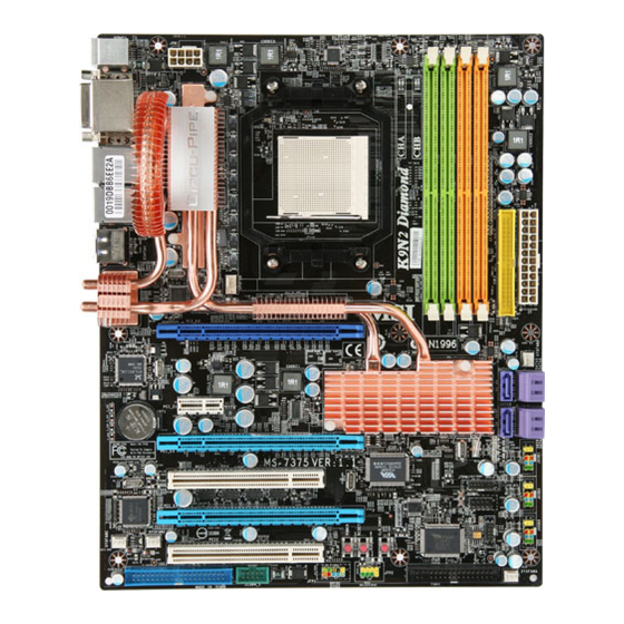
Page 13: Mainboard Layout
PCI_E1 780a SLI nFroce BATT PCI_E3 PCI1 VT6308P JTPM 1 JCI1 PCI_E4 JMB363 JCOM1 SYSFAN2 PCI2 P OWE R CLR_ CMOS Chip SYSFAN1 RE SET JFP1 JFP2 FDD 1 J1394_ 1 IDE 2 K9N2 Diamond Series (MS-7375 v1.X) ATX Mainboard... -
Page 14: Packing Checklist
Getting Started Packing Checklist 3-W ay SLI bridge cables MSI Driver/Utility CD (1 long, 2 short) MSI motherboard Power Cable SATA Cable IDE Cable 1394+USB Bracket X-Fi Xtreme Audio Card Floppy Cable (Optional) (optional) DVI-D to HDMI Back IO Shield User’s Guide... -
Page 15: Chapter 2. Hardware Setup
Hardware Setup Chapter 2 Hardware Setup This chapter provides you with the information about hardware setup procedures. While doing the installation, be careful in holding the components and follow the installation procedures. For some components, if you install in the wrong orientation, the components will not work properly. -
Page 16: Quick Components Guide
M S-7375 M ainboard Quick Components Guide CPU, p.2-3 DDR2 DIMMs, p.2-6 JPW1, p.2-8 CPUFAN, p.2-13 Back Panel IDE1, p.2-11 I/O, p.2-10 ATX1, p.2-8 SYSFAN3, PCI Express p.2-13 slots, p.2-18 SATA, p.2-12 JTPM1, p.2-15 PCI Slots, JUSB1~3, p.2-14 p.2-24 JCOM1, p.2-13 SYSFAN2, p.2-13 JCI1, p.2-14... -
Page 17: Cpu (Central Processing Unit)
If you do not have the heat sink and cooling fan, contact your dealer to purchase and install them before turning on the computer. For the latest information about CPU, please visit http://global.msi.com.tw/index. php?func=cpuform Important Overheating Overheating will seriously damage the CPU and system. - Page 18 M S-7375 M ainboard CPU Installation Procedures for Socket AM2/ AM2+ 1. Please turn off the power and unplug the power cord before Open the lever installing the CPU. Sliding the plate 90 degree 2. Pull the lever s ideways away from the socket.
- Page 19 Hardware Setup Installing CPU Cooler Set W hen you are installing the CPU, make sure the CPU has a heat sink and a cooling fan attached on the top to prevent overheating. If you do not have the heat sink and cooling fan, contact your dealer to purchase and install them before turning on the computer.
-
Page 20: Memory
M S-7375 M ainboard Memory These DIMM slots are used for installing memory modules. For more information on compatible components, please visit http://global.msi.com. tw/index.php?func=testreport DDR2 240-pin, 1.8V 56x2=112 pin 64x2=128 pin Dual-Channel Memory Population Rules In Dual-Channel mode, the memory modules can transmit and receive data with two data bus lines simultaneously. - Page 21 Hardware Setup Installing Memory Modules 1. The memory module has only one notch on the center and will only fit in the right orientation. 2. Insert the memory module vertically into the DIMM slot. Then push it in until the golden finger on the memory module is deeply inserted in the DIMM slot.
-
Page 22: Power Supply
M S-7375 M ainboard Power Supply ATX 24-Pin Power Connector: ATX1 This connector allows you to connect an ATX 24-pin power supply. To connect the ATX 24-pin power supply, make sure the plug of the pin 13 power supply is inserted in the proper orientation and the pins are aligned. - Page 23 Hardware Setup Important 1. Make sure that all the connectors are connected to proper ATX power sup- plies to ensure stable operation of the mainboard. 2. Power supply of 450 watts (and above) is highly recommended for system stability. Important Notification about Power Issue NForce chipset is very sensitive to ESD (Electrostatic Discharge), therefore this issue mostly happens while the users intensively swap memory modules under S5 (power-off) states, and the power code is plugged while installing modules.
-
Page 24: Back Panel
M S-7375 M ainboard Back Panel DVI-D Port Mouse ESATA Port USB Port Keyboard 1394 Port USB Port M ouse/Keyboard ® ® The standard PS/2 mouse/keyboard DIN connector is for a PS/2 mouse/keyboard. DVI-D Port The DVI-D (Digital Visual Interface-Digital) connector allows you to connect a LCD monitor. -
Page 25: Connectors
Hardware Setup Connectors IDE Connector: IDE1 / IDE2 This connector supports IDE hard disk drives, optical disk drives and other IDE devices. IDE1 IDE2 IDE1 (Primary IDE Connector) The first hard drive should always be connected to IDE1. IDE1 can connect a Master and a Slave drive. - Page 26 M S-7375 M ainboard Floppy Disk Drive Connector: FDD1 This connector supports 360KB, 720KB, 1.2MB, 1.44MB or 2.88MB floppy disk drive. FDD1 Serial ATA Connector: SATA1~6 This connector is a high-speed Serial ATA interface port. Each connector can con- nect to one Serial ATA device. SATA3/4 SATA6 SATA1/2...
- Page 27 Hardware Setup Fan Power Connectors: CPUFAN, SYSFAN1/ 2/ 3/ 4 The fan power connectors support system cooling fan with +12V. W hen connecting the wire to the connectors, always note that the red wire is the positive and should be connected to the +12V; the black wire is Ground and should be connected to GND. If the mainboard has a System Hardware Monitor chipset on-board, you must use a specially designed fan with speed sensor to take advantage of the CPU fan control.
- Page 28 M S-7375 M ainboard Front USB Connector: JUSB1/ JUSB2/ JUSB3 ® This connector, compliant with Intel I/O Connectivity Design Guide, is ideal for con- necting high-speed USB interface peripherals such as USB HDD, digital cameras, M P3 players, printers, modems and the like. Pin Definition SIGNAL SIGNAL...
- Page 29 Hardware Setup IEEE1394 Connector: J1394_1 This connector allows you to connect the IEEE1394 device via an optional IEEE1394 bracket. Pin Definition SIGNAL SIGNAL TPA+ TPA- Ground Ground TPB+ TPB- J1394_1 Cable power Cable power Key (no pin) Ground IEEE1394 Bracket TPM Module Connector: JTPM1 This connector connects to a TPM (Trusted Platform Module) module (optional).
- Page 30 M S-7375 M ainboard Front Panel Connectors: JFP1, JFP2 These connectors are for electrical connection to the front panel switches and LEDs. ® The JFP1 is compliant with Intel Front Panel I/O Connectivity Design Guide. Power Power Switch JFP1 Reset Switch JFP1 Pin Definition SIGNAL...
-
Page 31: Button
Hardware Setup Button This motherboard provides the following buttons for you to set the computer’s function. This section will explain how to change your motherboard’s function through the use of buttons. Clear CMOS Button: CLR_CMOS There is a CMOS RAM on board that has a power supply from external battery to keep the system configuration data. -
Page 32: Slots
M S-7375 M ainboard Slots PCI (Peripheral Component Interconnect) Express Slots The PCI Express slot supports the PCI Express interface expansion card. The PCI Express 2.0 x 16 supports up to 8.0 GB/s transfer rate. The PCI Express 2.0 x 8 supports up to 4.0 GB/s transfer rate. The PCI Express x 1 supports up to 250 MB/s transfer rate. - Page 33 Hardware Setup NVIDIA 3-Way SLI Technology NVIDIA 3-W ay SLI (Scalable Link Interface) technology allows three GPUs to run in sequence within a system to achieve up to triple the performance of a single graph- ics card. To utilize this technology, the three GPU cards must be connected by 3-Way SLI bridge cables.
- Page 34 M S-7375 M ainboard 1. Installing three graphics cards which support 3-W ay SLI technology on PCI Ex- press x16 slots. After three cards installed, SLI Bridge cables are required to connect the golden fingers on the top of these three graphics cards (fig.1). Please note that although you have installed three graphics cards, only the video outputs on the first card (which be installed in PCI_E2 slot) will work.
- Page 35 Hardware Setup Important 1. Mainboard photos shown in this section are for demonstration only. The appearance of your mainboard may vary depending on the model you purchase. 2. If you wish to use 2-way SLI, you must install the two graphics cards in one mazarine PCIE x16 s lot (PCI_E2) and the first blue PCIE x 16 slot (PCI_E3).
- Page 36 M S-7375 M ainboard 2. After the hardware installation is completed, power on the system and install the NVIDIA SLI driver. Reboot the system, a NVIDIA Control Panel will be provided for Multi-GPU control. Right click on windows desktop and select NVIDIA Control Panel.
- Page 37 Hardware Setup NVIDIA Hybrid SLI Technology Hybrid SLI technology, based on NVIDIA’s industry-leading SLI technology, delivers multi-GPU benefits when an NVIDIA mainboard GPU is combined with an NVIDIA discrete GPU. Enabling Hybrid SLI Technology Power off the system and install the NVIDIA SLI graphic card that supports Hybrid SLI technology.
- Page 38 M S-7375 M ainboard PCI (Peripheral Component Interconnect) Slots The PCI slots support LAN cards, SCSI cards, USB cards, and other add-on cards that comply with PCI specifications. At 32 bits and 33 MHz, it yields a throughput rate of 133 MBps. 32-bit PCI Slot PCI Interrupt Request Routing The IRQ, acronym of interrupt request line and pronounced I-R-Q, are hardware lines...
-
Page 39: Chapter 3 Bios Setup
BIOS Setup Chapter 3 BIOS Setup This chapter provides information on the BIOS Setup program and allows you to configure the system for optimum use. You may need to run the Setup program when: ² An error message appears on the screen during the system booting up, and requests you to run SETUP. -
Page 40: Entering Setup
M S-7375 M ainboard Entering Setup Power on the computer and the system will start POST (Power On Self Test) process. W hen the message below appears on the screen, press <DEL> key to enter Setup. Press DEL to enter SETUP If the message disappears before you respond and you still wish to enter Setup, restart the system by turning it OFF and On or pressing the RESET button. - Page 41 BIOS Setup Control Keys < ↑> Move to the previous item < ↓> Move to the next item < ←> Move to the item in the left hand < →> Move to the item in the right hand <Enter> Select the item <Esc>...
-
Page 42: The Main Menu
M S-7375 M ainboard The Main Menu Standard CM OS Features Use this menu for basic system configurations, such as time, date etc. Advanced BIOS Features ® Use this menu to setup the items of AMI special enhanced features. Integrated Peripherals Use this menu to specify your settings for integrated peripherals. - Page 43 BIOS Setup Load Fail-Safe Defaults Use this menu to load the default values set by the BIOS vendor for stable system performance. Load Optimized Defaults Use this menu to load the default values set by the mainboard manufacturer specifi- cally for optimal performance of the mainboard. Save &...
-
Page 44: Standard Cmos Features
M S-7375 M ainboard Standard CMOS Features The items in Standard CMOS Features Menu includes some basic setup items. Use the arrow keys to highlight the item and then use the <PgUp> or <PgDn> keys to select the value you want in each item. Date (MM:DD:YY) This allows you to set the system to the date that you want (usually the current date). - Page 45 BIOS Setup LBA/Large M ode This allows you to enable or disable the LBA Mode. Setting to Auto enables LBA mode if the device supports it and the devices is not already formatted with LBA mode disabled. DM A M ode Select DMA Mode.
-
Page 46: Advanced Bios Features
M S-7375 M ainboard Advanced BIOS Features Full Screen Logo Display This item enables you to show the company logo on the bootup screen. Settings are: [Enabled] Shows a still image (logo) on the full screen at boot. [Disabled] Shows the POST messages at boot. Quick Booting Setting the item to [Enabled] allows the system to boot within 10 seconds since it will skip some check items. - Page 47 BIOS Setup Primary Graphic’s Adapter This setting specifies which graphic card is your primary graphics adapter. PCI Latency Timer This item controls how long each PCI device can hold the bus before another takes over. W hen set to higher values, every PCI device can conduct transactions for a longer time and thus improve the effective PCI bandwidth.
- Page 48 M S-7375 M ainboard Boot Sequence Press <Enter> to enter the sub-menu and the following screen appears: 1st/ 2nd/ 3rd Boot Device The items allow you to set the first/ second/ third boot device where BIOS attempts to load the disk operating system. Boot From Other Device Setting the option to [Yes] allows the system to try to boot from other device.
-
Page 49: Integrated Peripherals
BIOS Setup Integrated Peripherals USB Controller This setting allows you to enable/disable the onboard USB controller. USB Device Legacy Support Select [Enabled] if you need to use a USB-interfaced device in the operating system. Onboard LAN Controller This item is used to enable/disable the onboard LAN controller. LAN Option ROM This item is used to decide whether to invoke the Boot ROM of the LAN controller. - Page 50 M S-7375 M ainboard RAID M ode This item allows you to enable/ disable the RAID function for extra RAID/ IDE controller. Select [RAID] will enable RAID. On-Chip ATA Devices Press <Enter> to enter the sub-menu and the following screen appears: On-Chip IDE Controller This item allows you to enable/ disable the IDE controller.
-
Page 51: Power Management Setup
BIOS Setup Power Management Setup Important S3-related functions described in this section are available only when your BIOS supports S3 sleep mode. ACPI Function This item is to activate the ACPI (Advanced Configuration and Power Management Interface) Function. If your operating system is ACPI-aware, such as W indows 2000/ XP, select [Enabled]. - Page 52 M S-7375 M ainboard Power Button Function This feature sets the function of the power button. Settings are: [Power On/Off] The power button functions as normal power on/ off button. [Suspend] W hen you press the power button, the computer enters the suspend/sleep mode, but if the button is pressed for more than four seconds, the computer is turned off.
- Page 53 BIOS Setup Resume By PCI-E Device W hen set to [Enabled], the feature allows your system to be awakened from the power saving modes through any event on PCI Express device. Resume By Onbaord LAN W hen set to [Enabled], the feature allows your system to be awakened from the power saving modes through any event on LAN device.
-
Page 54: H/W Monitor
M S-7375 M ainboard H/W Monitor Chassis Intrusion The field enables or disables the feature of recording the chassis intrusion status and issuing a warning message if the chassis is once opened. To clear the warning message, set the field to [Reset]. The setting of the field will automatically return to [Enabled] later. -
Page 55: Bios Setting Password
BIOS Setup BIOS Setting Password W hen you select this function, a message as below will appear on the screen: Type the password, up to six characters in length, and press <Enter>. The password typed now will replace any previously set password from CMOS memory. You will be prompted to confirm the password. -
Page 56: Cell Menu
D.O.T Control D.O.T. (Dynamic Overclocking Technology) is the automatic overclocking function, ’s newly developed CoreCell included in the MSI Technology. It is designed to detect the load balance of CPU while running programs, and to adjust the best CPU frequency automatically. W hen the motherboard detects CPU is running programs, it will speed up CPU automatically to make the program run smoothly and faster. - Page 57 BIOS Setup [Disabled] Disable Dynamic Overclocking. [Private] 1st level of overclocking, increasing the frequency by 1%. [Sergeant] 2nd level of overclocking, increasing the frequency by 3%. [Captain] 3rd level of overclocking, increasing the frequency by 5%. [Colonel] 4th level of overclocking, increasing the frequency by 7%. [General] 5th level of overclocking, increasing the frequency by 10%.
- Page 58 M S-7375 M ainboard Adjust CPU FSB Frequency (M Hz) This item allows you to select the CPU Front Side Bus clock frequency (in MHz). Adjust CPU Ratio This item is used to adjust CPU clock multiplier (ratio). It is available only when the processor supports this function.
- Page 59 BIOS Setup SLI-Ready Memory Setting the item to [Auto] upgrades the memory module performance automati- cally when you install a pair of EPP (Enhanced Performance Profiles)-enabled memory modules. FSB/DRAM Ratio This setting controls the ratio of CPU FSB Clock & DRAM Frequency to enable the CPU FSB &...
- Page 60 M S-7375 M ainboard NB Voltage (V) Adjust the North Bridge chipset voltage. HT Link Voltage (V) Adjust the Hyper-Transport link voltage. Spread Spectrum This setting is used to enable or disable the Spread Spectrum feature. W hen overclocking, always set it to [Disabled]. Important 1.
-
Page 61: User Settings
BIOS Setup USER SETTINGS Save Settings 1/2 Select this item and press “Enter” to save any changes you have made to your current settings. Load Settings 1/2 Select this item and press “Enter” to load settings from the store. 3-23... -
Page 62: Appendix A X-Fi Xtreme Audio Card
X-Fi Xtreme Audio Card Appendix A X-Fi Xtreme Audio Card The X-Fi Xtreme Audio card is powered by Creative CA0110 Audio chip. It supports up to 8-channel & SPDIF audio effect and allows users to attach 2, 4, 6, or 8 speakers for better surround sound effect. -
Page 63: Introduction
M S-7375 M ainboard Introduction X-Fi Xtreme Audio Card is powered by Creative CA0110 Digital Audio Controller. This card provides advanced audio functions by offering a comprehensive suite of software applications. The advanced tools and amazing features provided will allow you to experience a full array of exciting activities, such as listening to effects enhanced music, watching a multi-channel movie, playing the latest game or recording a high quality audio track. - Page 64 X-Fi Xtreme Audio Card Realistic Wave-Table Synthesis - 64-Voice polyphony and multi-timbral capability - 128 GM & GS compatible instruments and 10 drum kits - 2MB or 4MB GM SoundFont Bank included Sound Blaster Live! 24-bit Input/Output - Line level out (Front/ Side/ Rear/ Centre/ Subwoofer) or Headphone out - Line In / Microphone In - S/PDIF In and S/PDIF Out - Auxiliary Audio in...
-
Page 65: Hardware Installation
M S-7375 M ainboard Hardware Installation Installing the Card The interface of X-Fi Xtreme Audio Card is PCI-E x1. You can install it to the PCI-E x1 slot. Follow the steps below to install the card, then you can activate the advanced function and enjoy the audio effect. - Page 66 X-Fi Xtreme Audio Card Connecting the Speakers W hen you have set the Multi-Channel Audio Function mode properly in the software utility, connect your speakers to the correct jacks in accordance with the setting in software utility. n 2-Channel M ode for 2-Speaker Output Refer to the diagram and caption for the function of each jack on the back panel when 2-Channel Mode is selected.
- Page 67 M S-7375 M ainboard n 6-Channel M ode for 6-Speaker Output Refer to the diagram and caption for the function of each jack on the back panel when 6-Channel Mode is selected. 6-Channel Analog Audio Output 1 S/PDIF Out-Optical 2 MIC & Line-In 3 Line Out (Front channels) 4 No function 5 Line Out (Center and Subwoofer channel)
-
Page 68: Installing The Creative Audio Driver
X-Fi Xtreme Audio Card Installing the Creative Audio Driver You need to install the driver for Creative CA0110 to function properly before you can get access to 2-, 4-, 6- or 8- channel and SPDIF audio operations. Follow the proce- dures below to install the drivers for W indows 2000/ XP/ VISTA operating system. - Page 69 M S-7375 M ainboard 3. Select your region from the list . 4. Select the language that you need from the list . 5. On the next page, click Install to start the installation and follow the setup instruc- tions to complete. 6.
-
Page 70: Software Configuration
X-Fi Xtreme Audio Card Software Configuration After installing the creative audio driver, you are able to use the 2-, 4-, 6- or 8- channel and the SPDIF audio features. Double click on the creative volume control audio icon from the system tray at the lower-right corner of the screen to activate the Sound Blaster X-Fi Xtreme Audio Applications, simply click on each icon to enter the configuration screen. - Page 71 M S-7375 M ainboard Creative M ediaSource Go! Launcher Click on the Creative MediaSource Go! Launcher icon to enter its configuraton screen. Creatvie MediaSource Go! Launcher consists of various tabs such as Programs, Product Settings, Product Support and Companion Products. In each tab, you can access different applications, called Tasks.
- Page 72 X-Fi Xtreme Audio Card Soundfont Bank Manager ® Click on the SOUNDFONT BANK MANAGER icon to enter its configuraton screen. W ith SoundFont Bank Manager (SFBM), you can: click on this button to get the online help information - Load SoundFont banks Replace the default sounds on your computer with the high-quality sound of a SoundFont bank.
- Page 73 M S-7375 M ainboard Creative MediaSource Play/ Organizer Click on the Creative MediaSource Play/ Organizer icon to enter its configuraton screen. Creative MediaSource Player/ Oraganizer is your digital music center for playing , creating, organizing and transferring digital music. This is your ultimate all-in-one digital entertainment software.
- Page 74 X-Fi Xtreme Audio Card Entertainment M ode Console Click on the Entertainment Mode icon to enter its configuraton screen. In Entertainment Mode, you audio device is optimized for movie soundtrack and music playback. You can configure Entertainment Mode settings in the Entertainment Mode consloe. W ith the Entertainment Mode console, you can: click on this button to get the online help information - Adjust master volume or speaker volume, bass and treble levels.
- Page 75 M S-7375 M ainboard The following table lists the function of each control on the main interface. Close button - Click on this button to close the Entertainment Mode console. Minimize button - Click on this button to minimize the Entertainment Mode window to the task bar.
- Page 76 X-Fi Xtreme Audio Card Speaker & Headphone Click on the speaker button to enter its configuration screen. Here you can adjust your speakers configuration. Select the type of your speaker system, and adjust the volume and cuff frequency for your subwoofer. This is the main application to use for the following tasks: - Designating the number and configuration of speakers to use =>...
- Page 77 M S-7375 M ainboard X-Fi CMSS-3D Click on the X-Fi CMSS-3D button to enter its configuration screen. Creative MultiSpeaker Surround (CMSS) 3D makes ordinary two-channel (Left and Right Stereo) sound seem to surround you, even through only two speakers. For users with 5.1, 6.1, 7.1 multichannel speaker systems, CMSS can also simulate surround sound from ordinary stereo.
-
Page 78: Appendix B Nvidia Raid
nVidia RAID Appendix B nVidia RAID NVIDIA brings Redundant Array of Independent Disks (RAID) technology—which is used by the world’s lead- ing businesses—to the common PC desktop. This tech- nology uses multiple drives to either increase total disk space or to offer data protection. For all levels, RAID techniques optimize storage solutions by using multiple disks grouped together and treating them as a single storage resource. -
Page 79: Introduction
M S-7375 M ainboard Introduction System Requirement Operating System Support NVRAID supports the following operating systems: W indows XP, W indows Vista RAID Arrays NVRAID supports the following types of RAID arrays described in this section: RAID 0: RAID 0 defines a disk striping scheme that improves the disk read and write times for many applications. -
Page 80: Raid Configuraiton
nVidia RAID RAID Configuration Basic Configuration Instructions The following are the basic steps for configuring NVRAID: Non-Bootable RAID Array 1. Choose the hard disks that are to be RAID enabled in the system BIOS. (Refer the bios section for details.) 2. - Page 81 M S-7375 M ainboard Understanding the “Define a New Array” Window Use the Define a New Array window to • Select the RAID Mode • Set up the Striping Block • Specify which disks to use for the RAID Array The SATA ports are called channels and they are associated with adapters.
- Page 82 nVidia RAID Using the Define a New Array Window If necessary, press the tab key to move from field to field until the appropriate field is highlighted. • Selecting the RAID Mode By default, this is set to [Mirroring]. To change to a different RAID mode, press the down arrow key until the mode that you want appears in the RAID Mode box—either [Mirroring], [Striping], [RAID5], [Spanning], or [Stripe Mirroring].
- Page 83 M S-7375 M ainboard Completing the RAID BIOS Setup 1. After assigning your RAID array disks, press F7. The Clear disk data prompt appears. 2. Press Y if you want to wipe out all the data from the RAID array, otherwise press N.
-
Page 84: Installing Driver
Important Please follow the instruction below to make an “NVIDIA RAID Driver” for yourself. a. Insert the MSI CD into the CD-ROM drive. b. Click the “Browse CD” on the Setup screen. c. Copy all the contents in the \\nVidia\System\MCP72\IDE\WinXP\Sataraid\Floppy to a formatted floppy disk. -
Page 85: Nvidia Raid Utility Installation
M S-7375 M ainboard NVIDIA RAID Utility Installation Installing the NVIDIA MediaShield Software Under Windows (for Non-bootable RAID Array) The existing W indows Serial ATA driver must be upgraded to use the NVIDIA Serial ATA driver. This section describes how to run the setup application and install the RAID software which will upgrade the W indows SATA driver and install the RAID software. - Page 86 nVidia RAID Initializing and Using the Disk Array The RAID array is now ready to be initialized under W indows. 1. Launch Computer Management by clicking “Start” --> “Settings” --> “Control Panel” then open the “Administrative Tools” folder and double click on “Computer Management”.
- Page 87 M S-7375 M ainboard 5. Check the disk in the list if you want to make the array a dynamic disk, then click Next. The Completing the Initialize and Convert Disk W izard window appears. 6. Click Finish. The “Computer Management” window appears. The actual disks listed will depend on your system, and the unallocated partition is the total combined storage of two hard disks.
-
Page 88: Using Thenvmediashield Software
nVidia RAID Using the NVMediaShield Software Accessing the Storage Page To access the NVIDIA Control Panel Storage page: 1. Click Star-> Programs-> NVIDIA Corporation-> NVIDIA Control Panel-> Storage. 2. The NVIDIA Control Panel - Storage page appears. B-11... - Page 89 M S-7375 M ainboard Using the Storage Page From the Storage page, you can accomplish the following tasks: • Create an Array • Delete an Array • Rebuild an Array • Synchronize an Array • Designate a Spare Disk • Remove a Spare •...
- Page 90 nVidia RAID Designate a Spare Disk About Spare Disks You can designate a hard drive to be used as a spare drive for a RAID 1, RAID 0+1 or RAID 5 array2. The spare drive can take over for a failed disk. MediaShield RAID supports two types of spare drives: Free Disk A free disk is a disk that is not part of any RAID array, but can be used by any...
- Page 91 M S-7375 M ainboard Remove a Spare The Remove spare option appears only if you have a a RAID array with a spare disk allocated to it. Click Remov e spare to s tart the Remove Spare W izard and then follow the instructions.
- Page 92 nVidia RAID Specific M igrating Requirements The following table lists the disk requirements for a new RAID array for various migrating combinations. From New Array Disk Requirements m > n RAID 0 Number of disks in the new array must be greater than the original array. m =2, n =1 RAID 1 RAID 1 array must include two disks, converted from a one disk RAID 0...
- Page 93 M S-7375 M ainboard View Storage Information • You can use the Storage page to view the following storage information about the hard drives in your system: - W hich RAID arrays are set up - The process state of each array - W hich drives are configured for each RAID array in your system - W hich drives are designated as free disks - Information about each drive, such as size and model...
-
Page 94: Appendix C Jm Icron Raid Introduction
JMicron RAID Appendix C JMicron RAID Introduction This appendix will assist users in configuring and enabling RAID functionality on platforms The JMicron RAID solution supports RAID level 0 (striping), RAID level 1 (mirroring), RAID level 10 (striping and mirroring) and JBOD (Concatenate). -
Page 95: Introduction
M S-7375 M ainboard Introduction JMicron JMB363 offers RAID level 0 (Striping), RAID level 1 (Mirroring and Duplexing), RAID level 10 (A Stripe of Mirrors) and JBOD (Concatenate). RAID 0 breaks the data into blocks which are written to separate hard drives. Spreading the hard drive I/O load across independent channels greatly improves I/O performance. -
Page 96: Jmicron Raid Bios Utility
JMicron RAID JMicron RAID BIOS Utility Be sure to set RAID mode for the JMicron 36x ATA Controller in BIOS before configuring the JMicron BIOS utility. After that, save the configuration and exit. During boot up (POST), press CTRL+J to enter the JMicron BIOS RAID utility. The RAID Utility menu screen will be displayed. - Page 97 M S-7375 M ainboard Creating RAID set 1. Select “Create RAID Disk Drive”. Then press <Enter>. 2. Then in the Name field, specify a RAID set name and then press the <Enter> to go to the next field. 3. Choose a 0-Striped, a 1-Mirror, or a JBOD-Concatenate combination set and then press <Enter>...
- Page 98 JMicron RAID 4. In the Hard Disk Disk List menu, use <Space> key to select the disks you want to create for the RAID set, then click <Enter> key to finish selection. 5. Then select the block value (stripe value) for the RAID array by using the “upper arrow”...
- Page 99 M S-7375 M ainboard 6. Then select the capacity of the RAID set in the Size field. The default value is the maximum capacity of the selected disks. Then press <Enter> to the Confirm Crea- tion field. 7. The Creation field will display a message to ask you to confirm the creation. Then press <Y>...
- Page 100 JMicron RAID Deleting RAID set 1. Select “Delete RAID Disk Drive”. Then press <Enter>. 2. In the RAID Disk Driver List menu, use <Space> key to select the RAID set you want to delete. Then press <Del> key. 3. Press “Y” to accept the deletion when a deletion message is appeared.
- Page 101 M S-7375 M ainboard Revert HDD to non-RAID Select Revert HDD to non-RAID and press <Enter>. In the Hard Disk Driver List menu use <Space> key to select the disks you want to revert then click <Enter> key. The following screen appears, press <Y> key to remove any RAID structures from the drives.
- Page 102 JMicron RAID Solving a Mirror Conflict A Mirror conflict occurs when both disks in a RAID 1 (Mirror) configuration are unplugged from the system in turn, then plugged in again. Since both disks contain exactly the same data, the system will be unable to determine which of the two is the source drive.
- Page 103 M S-7375 M ainboard Rebuilding a Mirror drive W hen one of the disk in a RAID 1 (Mirror) configuration is unplugged from the system, then plugged in again, a dialogue box appears to ask you to rebuild the Mirror drive. Press <Y>...
-
Page 104: Installing Driver
Important Please follow the instruction below to make an “JMicron RAID Driver” for yourself. 1. Insert the MSI CD into the CD-ROM drive. 2. Click the “Browse CD” on the Setup screen. 3. Copy all the contents in the for XP: \\nvidia\IDE\JM icron\JM B363\Floppy32 (for 32-bit OS) or Floppy64 (for 64-bit OS) to a formatted floppy disk. - Page 105 M S-7375 M ainboard † Existing Windows Vista/XP Driver Installation 1. Insert the MSI CD into the CD-ROM drive. 2. The CD will auto-run and the setup screen will appear. 3. Under the Driver tab, click on JMicron JMB363 Drivers.
-
Page 106: Jmicron Raid Configurer
JMicron RAID JMicron RAID Configurer There is an application called JMRaidTool which helps you perform the following tasks of JMicron RAID. • Viewing RAID Array Configurations View an array configuration (mirrored, striped) • Creating RAID Arrays • Deleting a RAID Array •... - Page 107 M S-7375 M ainboard Create RAID JMRaidTool supports the creation of RAID 0, 1, 0+1 and JBOD. 1. Left-click the “Create Raid” button. 2. A CREATE RAID W IZARD dialogue will display on the screen, following the descrip- tion of every step to complete the creation. Create RAID from Existing Disk You can combine the Existing Disk (Source disk may content OS and Data) with other HD (must be larger than source Disk) to be RAID.
- Page 108 JMicron RAID Remove RAID There are two ways you can choose to remove RAID. Way 1 1. Right-click the name of the disk array you want to delete and the “Remove” menu will appear. Select the “Remove Raid” of the pop-up menu. 2.
- Page 109 M S-7375 M ainboard Way2 1. Left-Click the “Remove Raid” icon on the toolbar. 2. A “REMOVE RAID” wizard dialogue will display on the screen, following the de- scription of every step to complete the deletion. Rebuild RAID RAID 1, 0+1 can be rebuilt while RAID 0, JBOD cannot be rebuilt. There are two ways you can choose to rebuild RAID.
- Page 110 JMicron RAID 2. Select “Rebuild Raid”. 3. A “REBUILD RAID W IZARD” dialogue will display on the screen, following the description of every step to complete the rebuilding. Way 2 1. If the disk array needs to rebuild then the rebuild button will be enabling on the toolbar.
- Page 111 M S-7375 M ainboard 2. Left-Click the “Rebuild Raid” button on the toolbar. 3. A “REBUILD RAID W IZARD” dialogue will display on the screen, following the description of every step to complete the rebuilding. Solve Mirror Conflict If the conflict occurs, it will show the “REBUILDING RAID WIZARD” dialogue to ask you if you want to rebuild RAID, following the description of every step to rebuild the RAID.
-
Page 112: Appendix D Dual Core Center
Dual Core Center Dual CoreCenter, the most useful and powerful utility that MSI has spent muc h researc h and ef forts to develop, helps users to monitor or configure the hard- ware status of MSI Mainboard & MSI Graphics card in windows, such as CPU/GPU clock, voltage, fan speed and temperature. -
Page 113: Activating Dual Core Center
Activating Dual Core Center Once you have your Dual Core Center installed (locate the setup source file in the setup CD accompanying with your mainboard, path: Utility --> MSI Utility --> Dual Core Center), it will have an icon in the system tray, a short cut icon on the desktop, and a short cut path in your “Start-up”... -
Page 114: Main
Dual Core Center Main Before using this utility, we have to remind you: only when installing the MSI V044 (V044 has to install with the version 8.26 or newer driver)/ V046 or V060 graphics card can activate the full function of this utility. If you install a graphics card of other brand, only hardware status of the MSI mainboard would be available. - Page 115 M S-7375 M ainboard AV/ Game/ Office/ Silence/ Cool MSI provides five common settings for different environments. The settings had been set to optimal values to reac h better performanc e in eac h environment. Click the button you need.
-
Page 116: Dot(Dyanmic Overclocking
Dynamic Overclocking Technology is an automatic overclocking function, included in ’s newly developed Dual CoreCenter Technology. It is designed to detect the the MSI loading of CPU/ GPU while running programs, and to over-clock automatically. When the motherboard detects that the loading of CPU is exceed the default threshold for a time, it will speed up the CPU and fan automatically to make the system run smoother and faster. -
Page 117: E (Efficiency
M S-7375 M ainboard E (Efficiency) The revolutionary PW M (Pulse W idth Modulation) design created by MSI is called Dual-Channel PW M. It is designed to create better power converting based on 4- phase power. Through the Dual-Channel PW M, power loss can be reduced, which allows CPU to receive higher power efficiency in higher loading condition. -
Page 118: Clock
Dual Core Center Clock In the Clock sub-menu, you can see clock status (including FSB/ CPU clock of mainboard and GPU/ memory clock of graphics card) of your system. And you can select desired value for overclocking. There will be several items for you to select for overclocking after you click button. -
Page 119: Voltage
M S-7375 M ainboard Voltage In the Voltage sub-menu, you can see voltage status (including Vcore, memory, GPU voltage... etc.) of your system, and you can select desired value for overclocking. It will show several items to select for overclocking after you click the button. -
Page 120: Fan Speed
Dual Core Center FAN Speed In the FAN Speed sub-menu, you can read fan status of your system. Select higher speed for better cooling effect. There are several sections for you to change the fan speed to a section after clicking button. -
Page 121: Temperature
M S-7375 M ainboard Temperature In the Temperature sub-menu, you can see temperature status of your system. On the underside, it shows the graphs of the temperatures. Only the curves of the item which the button is lit up with red color will be shown. D-10... -
Page 122: User Profile
Dual Core Center User Profile In the User Profile sub-menu, click the setting button that besides the user profile bar, and the next screen will appear. Here you can define the clock/ fan speed/ voltage by your need, click the button to choose a value quickly, or click the plus / minus sign button to... - Page 123 M S-7375 M ainboard Use the draw bar to set the max system temperature. W hen the system temperature exceeds the threshold you defined, the system will pop up a warning message and shut down the system. Use the draw bar to set the minimal fan speed. When the fan speed is lower than the threshold you defined, the system will pop up a warning message.
Need help?
Do you have a question about the K9N2 Diamond Series and is the answer not in the manual?
Questions and answers