Table of Contents
Advertisement
FCC-B Radio Frequency Interference Statement
This equipment has been tested and found to comply with the limits for a class B digital
device, pursuant to part 15 of the FCC rules. These limits are designed to provide
reasonable protection against harmful interference in a residential installation. This
equipment generates, uses and can radiate radio frequency energy and, if not installed and
used in accordance with the instruction manual, may cause harmful interference to radio
communications. However, there is no guarantee that interference will occur in a particular
installation. If this equipment does cause harmful interference to radio or television
reception, which can be determined by turning the equipment off and on, the user is
encouraged to try to correct the interference by one or more of the measures listed below.
n
Reorient or relocate the receiving antenna.
n
Increase the separation between the equipment and receiver.
n
Connect the equipment into an outlet on a circuit different from that to which the
receiver is connected.
n
Consult the dealer or an experienced radio/ television technician for help.
Notice 1
The changes or modifications not expressly approved by the party responsible for
compliance could void the user's authority to operate the equipment.
Notice 2
Shielded interface cables and A.C. power cord, if any, must be used in order to comply with
the emission limits.
VOIR LA NOTICE D'NSTALLATION AVANT DE RACCORDER AU RESEAU.
Micro-Star International
MS-7506
G52-75061X1
Advertisement
Table of Contents

Subscribe to Our Youtube Channel
Related Manuals for MSI K9NGM4 Series


Summary of Contents for MSI K9NGM4 Series
- Page 1 FCC-B Radio Frequency Interference Statement This equipment has been tested and found to comply with the limits for a class B digital device, pursuant to part 15 of the FCC rules. These limits are designed to provide reasonable protection against harmful interference in a residential installation. This equipment generates, uses and can radiate radio frequency energy and, if not installed and used in accordance with the instruction manual, may cause harmful interference to radio communications.
-
Page 2: Copyright Notice
Copyright Notice The material in this document is the intellectual property of MICRO-STAR INTERNATIONAL. We take every care in the preparation of this document, but no guarantee is given as to the correctness of its contents. Our products are under continual improvement and we reserve the right to make changes without notice. -
Page 3: Safety Instructions
Safety Instructions Always read the safety instructions carefully. Keep this User Manual for future reference. Keep this equipment away from humidity. Lay this equipment on a reliable flat surface before setting it up. The openings on the enclosure are for air convection hence protects the equipment from overheating. - Page 4 INTRODUCTION Thank you for choosing the K9NGM4 Series (MS-7506 V1.X) Micro-ATX mainboard. The ® K9NGM4 Series is design based on NVIDIA MCP68S / MCP68PVNT single chipset for ® optimal system efficiency. Designed to fit the advanced AMD Socket AM2 Athlon...
-
Page 5: Specifications
® l AMD Athlon 64, Athlon 64 X2 and Sempron processors in socket AM2 package (For the latest information about CPU, please visit: http://global.msi.com.tw/index.php?func=cpuform) Supported FSB l 1000 MHz Chipset ® l NVIDIA MCP68S / MCP68PVNT single chipset (Optional) Memory Support l DDR2 533/667/800 SDRAM (4GB Max) l 2 DDR2 DIMMs (240 pin / 1.8V) -
Page 6: Form Factor
Floppy l 1 floppy port l Supports 1 FDD with 360KB, 720KB, 1.2MB, 1.44MB and 2.88MB Connectors l Back panel - 1 PS/2 mouse port - 1 PS/2 keyboard port - 1 parallel port - 1 COM port - 1 VGA port - 1 1394 port (Optional) - 1 LAN jack - 4 USB 2.0 ports... -
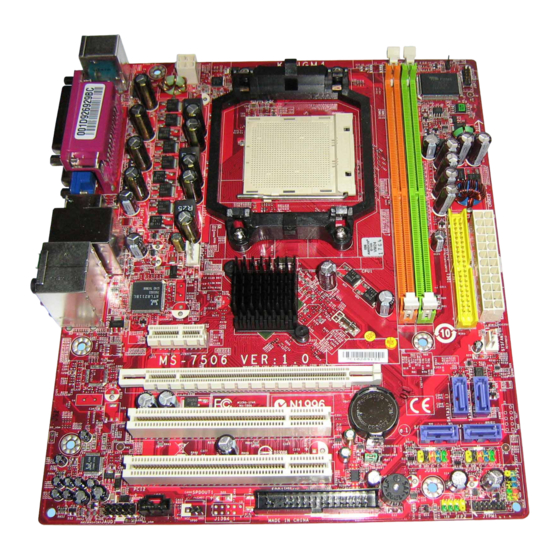
Page 7: Rear Panel
REAR PANEL The rear panel provides the following connectors: Parallel Port LAN Jack 1394 Port Mouse (Optional) Line-In RS-Out Line-Out CS-Out SS-Out Keyboard COM Port VGA Port USB Ports HARDWARE SETUP This chapter tells you how to install the CPU, CPU cooler set and memory modules, as well as how to setup the jumpers on the mainboard. -
Page 8: Installing Amd Socket Am2 Cpu Cooler Set
Installing AMD Socket AM2 CPU Cooler Set When you are installing the CPU, make sure the CPU has a heat sink and a cooling fan attached on the top to prevent overheating. If you do not have the heat sink and cooling fan, contact your dealer to purchase and install them before turning on the computer. - Page 9 +3.3V ATX 24-Pin Power Connector: ATX1 +12V This connector allows you to connect an ATX 24-pin power +12V supply. To connect the ATX 24-pin power supply, make sure the 5VSB plug of the power supply is inserted in the proper orientation and PW R OK the pins are aligned.
- Page 10 Important: Please do not fold the Serial ATA cable into 90-degree angle. Otherwise, data loss may occur during transmission. Fan Power Connectors: CPUFAN1, SYSFAN1 +12V Sensor The fan power connectors support system cooling fan with +12V. Control When connecting the wire to the connectors, always note that the red wire is the positive and should be connected to the +12V;...
- Page 11 MIC2_JD VCC5 Front Panel Audio Connector: JAUD1 Line_JD(10) (2)GND (2)GND (1)MIC_L Line-out_L(9) This connector allows you to connect the front panel audio and is MIC_R Front to Sense Line-out_R ® compliant with Intel Front Panel I/O Connectivity Design Guide. USB0+ Front USB Connector: JUSB1/ JUSB2 USB0- ®...
-
Page 12: Pci Interrupt Request Routing
PCI (Peripheral Component Interconnect) Slot The PCI slot supports LAN card, SCSI card, USB card, and other add-on cards that comply with PCI specifications. Important: When adding or removing expansion cards, make sure that you unplug the power supply first. Meanwhile, read the documentation for the expansion card to configure any necessary hardware or software settings for the expansion card, such as jumpers, switches or BIOS configuration. -
Page 13: Bios Setup
BIOS Setup Power on the computer and the system will start POST (Power On Self Test) process. When the message below appears on the screen, press <DEL> key to enter Setup. Press DEL to enter SETUP If the message disappears before you respond and you still wish to enter Setup, restart the system by turning it OFF and On or pressing the RESET button. -
Page 14: Cell Menu
Load Fail-Safe Defaults Use this menu to load the default values set by the BIOS vendor for stable system performance. Load Optimized Defaults Use this menu to load factory default settings into the BIOS for stable system performance operations. BIOS Setting Password Use this menu to set BIOS setting Password. - Page 15 Processor Frequency Multiplier It shows the processor frequency multiplication. Read-only. Advance DRAM Configuration > MCT Timing Mode This field has the capacity to automatically detect all of the DRAM timing. If you set this field to [Manual], you can select the DRAM timing manually. Advance DRAM Configuration >...
-
Page 16: Load Optimized Defaults
Load Optimized Defaults You can load the default values provided by the mainboard manufacturer for the stable performance.
Need help?
Do you have a question about the K9NGM4 Series and is the answer not in the manual?
Questions and answers