Table of Contents
Advertisement
Quick Links
Advertisement
Table of Contents

Related Manuals for MSI K9ND Master-A4R


Summary of Contents for MSI K9ND Master-A4R
- Page 1 K9ND Master MS-9182 (V1.X) Server Board G52-91821X1...
-
Page 2: Copyright Notice
Alternatively, please try the following help resources for further guidance. Visit the MSI website at faq/esc_faq_list.php updates, and other information. Contact our technical staff at http://support.msi.com.tw/. Date December 2006 http://www.msi.com.tw/program/service/faq/ for FAQ, technical guide, BIOS updates, driver... -
Page 3: Safety Instructions
Safety Instructions Always read the safety instructions carefully. Keep this User’s Manual for future reference. Keep this equipment away from humidity. Lay this equipment on a reliable flat surface before setting it up. The openings on the enclosure are for air convection hence protects the equip- ment from overheating. -
Page 4: Fcc-B Radio Frequency Interference Statement
FCC-B Radio Frequency Interference Statement T h is eq uip men t h as been tested and found to c omply with the limits for a Class B digital device, pursuant to Part 15 of the FCC Rules. These limits are designed to provide reasonable protection against harmful interference in a residential installation. -
Page 5: Weee (Waste Electrical And Electronic Equipment) Statement
WEEE (Waste Electrical and Electronic Equipment) Statement... -
Page 8: Table Of Contents
Copyright Notice ... ii Trademarks ... ii Revision History ... ii Technical Support ... ii Safety Instructions ... iii FCC-B Radio Frequency Interference Statement ... iv W EEE (Waste Electrical and Electronic Equipment) Statement ... v Chapter 1 Getting Started ... 1-1 Mainboard Specifications ... - Page 9 NMI Button: JID1 ... 2-18 I2C Bus Connector: CN7 ... 2-18 FW H/LPC Debugging Pin Header: J2 ... 2-18 Jumper ... 2-19 OPMA Share NIC Jumper: J9 ... 2-19 BIOS Recovery Jumper: J7 ... 2-19 Clear CMOS Jumper: JBAT1 ... 2-19 Slot ...
- Page 10 Setting Up a Spare RAID Disk ... A-13 Morphing From One RAID Array to Another ... A-17 Hot Plug Array ... A-18 Initializing a RAID Array ... A-19 Rebuilding a RAID Array ... A-22 Synchronizing a RAID Array ... A-25 Usind Disk Alert ...
-
Page 11: Chapter 1 Getting Started
Getting Started Chapter 1 Getting Started Thank you for choosing the K9ND Master (MS-9182 v1. X), an excellent SSI server board from MSI. Based on the innovative nVIDIA MCP55 Pro chipset for optimal system efficiency, the K9ND Master accom- ®... -
Page 12: Mainboard Specifications
MS-9182 Server Board Mainboard Specifications Processor - Supports Dual AMD Opteron in the 1207-pin lidded ceramic micro PGA, from 1.4 – 2.8 GHz support - Supports HyperTransport technology - Meets thermal requirements Core Chipsets - Northbridge: nVIDIA MCP55 Pro - LPC Super I/O controller W 83627EHG... - Page 13 - 2 PCI-Express x8 slots - 1 HTX slot for Infini-band card (with riser card, optional) Form Factor - SSI Form Factor: 12” x 13” M ounting - 9 mounting holes For more information on compatible components, please visit http://www.msi.com.tw/program/products/server/svr/pro_svr_qvl.php Getting Started...
- Page 14 MS-9182 Server Board System Management MSI Server Management IPMI 2.0 MS-95L6 OPMA card (with H8S) and MSI iConsole AP with support for IPMI 2.0 MS-95L6 OPMA Card Specifications l BMC Chip - H8S 200-pin - Host hardware interface: LPC interface...
-
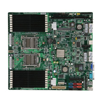
Page 15: Mainboard Layout
Mainboard Layout CPU0 JPWR3 CPU1 K9ND Master (MS-9182 v1.X) SSI Server Board Getting Started JFP3 JUSB1 JFP1 P0_DIMM 8 P0_DIMM7 HTX_E1 PCIE1 P0_DIMM6 P0_DIMM5 P0_DIMM4 BROADCOM P0_DIMM3 BCM5715 P0_DIMM2 P0_DIMM 1 JBAT1 BATT Winbond W83627EHG SYS_FAN1 nVIDIA JPBT1 MCP55 Pro... - Page 16 MS-9182 Server Board...
-
Page 17: Chapter 2 Hardware Setup
Hardware Setup Chapter 2 Hardware Setup This chapter provides you with the information about hardware setup procedures. While doing the installation, be careful in holding the components and follow the installation procedures. For some components, if you install in the wrong orientation, the components will not work properly. -
Page 18: Quick Components Guide
MS-9182 Server Board Quick Components Guide DIMM Slots, p.2-6 SYS_FAN1, p.2-13 CPU, p.2-3 JPWR3, p.2-8 CPU0_FAN, CPU1_FAN, p.2-13 DIMM Slots, p.2-6 HTX Slot, p.2-20 JUSB1, p.2-14 J F P 1 , p.2-16 J F P 3 , JSSI1, p.2-15 p.2-16 J5, p.2-17... -
Page 19: Cpu (Central Processing Unit)
W hen you are installing the CPU, make sure that you install the cooler to prevent the CPU from overheating. If you do not have the CPU cooler, contact your dealer to purchase and install it before turning on the computer. For the latest information about CPU, please visit http://www.msi.com.tw/program/ products/server/svr/pro_svr_qvl.php. Important 1. -
Page 20: Socket 1207 Cpu Installation
MS-9182 Server Board Socket 1207 CPU Installation 1. Locate the first CPU socket. (The CPU has a plastic cap on it to protect the contact from damage. Before install- ing the CPU, always cover it to pro- tect the socket pins.) 2. - Page 21 5. After confirming the CPU direction for correct mating, put down the CPU in the socket housing frame. Be sure to grasp on the edge of the CPU base. Note that the alignment keys are matched. 6. Visually inspect if the CPU is seated well into the socket.
-
Page 22: Memory
MS-9182 Server Board Memory The mainboard supports up to 16 Registered ECC DDRII 400/533/667 DIMM slots to provide the maximum of 32GB memory capacity. For more information on compatible components, please visit http://www.msi.com. tw/program/products/server/svr/pro_svr_qvl.php. DDRII 240-pin, 1.8V Memory Population Rules... -
Page 23: Memory Frequency Vs. Core Multiplier
Memory Frequency vs. Core Multiplier The DDRII DIMM operates different frequency when using different CPU. For example, when using 2.4GHz CPU the DDRII 667MHz DIMM will operate at 600MHz. Installing DDRII Modules 1. The memory module has only one notch on the center and will only fit in the right orientation. -
Page 24: Power Supply
MS-9182 Server Board Power Supply SSI 24-Pin System Power Connector: JPWR2 This connector allows you to connect to an SSI power supply. To connect to the SSI power supply, make sure the plug of the power supply is inserted in the proper orientation and the pins are aligned. -
Page 25: Back Panel
Back Panel M ou se Keyboard Serial Port VGA Port M ouse/Keyboard Connector ® The standard PS/2 mouse/keyboard DIN connector is for a PS/2 USB Connectors The OHCI (Open Host Controller Interface) Universal Serial Bus root is for attaching USB devices such as keyboard, mouse, or other USB-compatible devices. Serial Port Connector The serial port is a 16550A high speed communications port that sends/ receives 16 bytes FIFOs. - Page 26 MS-9182 Server Board LAN LEDs RJ45 NIC 0 Linkage (Left Side) RJ45 NIC 0 Mode (Right Side) RJ45 NIC 1 Linkage (Left Side) RJ45 NIC 1 Mode (Right Side) RJ45 NIC 3 Linkage (Left Side) RJ45 NIC 3 Mode (Right Side)
-
Page 27: Connectors
Connectors Chassis Intrusion Switch Connector: J10 This connector connects to a 2-pin chassis switch. If the chassis is opened, the switch will be short. The system will record this status and show a warning mes- sage on the screen. To clear the warning, you must enter the BIOS utility and clear the record. -
Page 28: Serial Ata Connectors: Sata_0 ~ Sata_3
MS-9182 Server Board Serial ATA Connectors: SATA_0 ~ SATA_3 SATA_0 ~ SATA_3 are high-speed SATA II interface ports and support SATA II data rates of 300MB/s. Each SATA II connector can connect to 1 hard disk device and is fully compliant with Serial ATA 2.0 specifications. -
Page 29: Scsi Led Connector: J6
SCSI LED Connector: J6 Connect the J6 to the LED connector on the add-on SCSI adaptor and the HDD LED will blink when add-on SCSI device is active. Fan Power Connectors: CPU0_FAN, CPU1_FAN, SYS_FAN1 The fan power connectors support system cooling fan with +12V. W hen connecting the wire to the connectors, always take note that the red wire is the positive and should be connected to the +12V, the black wire is Ground and should be connected to GND. -
Page 30: Serial Port Connector: Com 2
MS-9182 Server Board Serial Port Connector: COM 2 The mainboard provides one 9-pin header as serial port COM 2. The port is a 16550A high speed communication port that sends/receives 16 bytes FIFOs. You can attach a serial mouse or other serial devices directly to it. -
Page 31: Front Panel Connectors: Jssi1, Jfp1, Jfp2, Jfp3
Front Panel Connectors: JSSI1, JFP1, JFP2, JFP3 The mainboard provides 4 front panel connectors for electrical connection to the front panel/back plane switches and LEDs. The JSSI1 & JFP1 connect the front panel and the back plane; the JFP2 connects the SAS signal; the JFP3 connects the LAN LED and system LED signal. - Page 32 MS-9182 Server Board Description SFAN4_SENS CFAN1_SENS SFAN1_SENS SFAN7_SENS CFAN2_SENS SFAN2_SENS CFAN3_SENS SFAN8_SENS SFAN3_SENS SFAN6_SENS CFAN4_SENS SFAN5_SENS POWRE_LED_N POWER_LED_P FAN_LED3 ID_LED_C ID_LED_A COM2_DCDJ C_PIN3 C_PIN7 C_PIN9 JFP2 JFP3 2-16 JFP1 JFP1 Pin Definition Description CFAN1_PWM CFAN2_PWM SFAN1_PWM SFAN2_PWM SFAN3_PWM SFAN4_PWM FAN_LED1...
-
Page 33: Power Switch Connector: Jpbt1
The J5 is used to connect the ICMB SMBus and the J1 is for the IPMB SMBus. OPMA Connector: CN6 OPMA (Open Platform Management Architecture) is an open standard for server management subsystems. Users may connect MSI’s proprietary MS-95L6 OPMA card or other BMC (Baseboard Management Controller) card to this connector. MS-95L6 OPMA Card... -
Page 34: Nmi Button: Jid1
MS-9182 Server Board NMI Button: JID1 W hen the Operating System suffers from critical errors and consequently hangs, users may press this NMI (Non Maskable Interrupt) button to log system errors. I2C Bus Connector: CN7 The mainboard provides one I2C (also known as I connect System Management Bus (SMBus) interface. -
Page 35: Jumper
Jumper OPMA Share NIC Jumper: J9 This jumper works as a switch for OPMA to share different network interface cards (NIC). System Configure Jumper: J7 This jumper determines which mode the system will enter while powered on. During Normal Mode, the system will enter the assigned OS as usual. During Configure Mode, the system will directly enter BIOS setup utility. -
Page 36: Slot
MS-9182 Server Board Slot PCI (Peripheral Component Interconnect) Slot The PCI-class slots support LAN cards, SCSI cards, USB cards, VGA cards, and other add-on cards that comply with PCI specifications. PCI Express architecture provides a high performance I/O infrastructure for Desktop Platforms with transfer rates starting at 2.5 Giga transfers per second over a PCI... -
Page 37: Pci Interrupt Request Routing
PCI Interrupt Request Routing The IRQ, acronym of interrupt request line and pronounced I-R-Q, are hardware lines over which devices can send interrupt signals to the microprocessor. The PCI IRQ pins are typically connected to the PCI bus pins as follows: DEVICE INT Pin ATI VGA... - Page 38 MS-9182 Server Board 2-22...
-
Page 39: Chapter 3 Bios Setup
Chapter 3 BIOS Setup This chapter provides information on the BIOS Setup program and allows you to configure the system for optimum use. You may need to run the Setup program when: ² An error message appears on the screen during the system booting up, and requests you to run SETUP. -
Page 40: Entering Setup
MS-9182 Server BoardB Entering Setup Power on the computer and the system will start POST (Power On Self Test) process. W hen the message below appears on the screen, press <F2> key to enter Setup. Press F2 to enter SETUP If the message disappears before you respond and you still wish to enter Setup, restart the system by turning it OFF and On or pressing the RESET button. -
Page 41: Control Keys
Control Keys <F1> or <Alt-H> <Esc> arrow keys arrow keys <Home> or <End> <PgUp> or <PgDn> <F5> or <-> <F6> or <+>or <Space> <F9> <F10> <Enter> Getting Help After entering the Setup menu, the first menu you will see is the Main Menu. M ain M enu The main menu lists the setup functions you can make changes to. -
Page 42: The Menu Bar
MS-9182 Server BoardB The Menu Bar Once you enter PhoenixBIOS Setup Utility, the Main Menu will appear on the screen. On the Main Menu screen, you will see basic BIOS settings including system time & date, and the setup categories the BIOS supplies. Use Arrow keys to move among the items and menus, and make changes to the settings. - Page 43 Main The items inside the Main menu are for basic system information and configuration. Each item includes none, one or more setup items. Use the Up/Down arrow keys or <Tab> to highlight the item or field you want to modify and use the <+> or <-> key to switch to the value you prefer.
- Page 44 MS-9182 Server BoardB [LBA Mode Control] [32-Bit I/O] [Tranfer Mode] [Ultra DMA Mode] QuickBoot M ode Setting the item to [Enabled] allows the system to boot within 5 seconds since it will skip some check items. Boot-time Diagnostic Screen Select [Enabled] if you want to view the system diagnostic screen during boot-time. Summary Screen Select [Enabled] if you want to view the system summary screen.
-
Page 45: Advanced
Advanced Items in the menu are divided into several sub-menus. Each sub-menu provides more settings. To enter the sub-menu, highlight the sub-menu you want to configure and press <Enter>. Installed O/S W hen multiple operating systems are installed in your system, use this setting to select the major operating system that will be used most commonly. - Page 46 MS-9182 Server BoardB NumLock This setting is to set the Num Lock status when the system is powered on. Setting to [On] will turn on the Num Lock key when the system is powered on. Setting to [Off] will allow users to use the arrow keys on the numeric keypad. PState Configuration ACPI P-state (Performance) control algorithm’s goal is to optimize the runtime power consumption without significantly impacting performance.
- Page 47 among the processors. The operating system is then unable to use NUMA optimizations, and the memory space is treated as if the system were an SMP system. SW M em Hole Remap p This setting enables the software to remap the physical memory to an address higher than 00E0.
- Page 48 MS-9182 Server BoardB of checking the integrity of data in DRAM. ECC provides more elaborate error detection than parity; ECC can detect multiple-bit errors and can locate and correct single-bit errors. ECC Error Log This setting logs the ECC error. Chipkill Chipkill is a new Advanced ECC (Error Correction Code) memory technology that protects servers from system downtime caused by memory failures.
- Page 49 BIOS Setup System Health These items display the current status of all of the monitored hardware devices/ components such as CPU voltages, temperatures and all fans’ speeds. CPU and System Voltage This field shows the CPU and system voltages. 3-11...
- Page 50 MS-9182 Server BoardB System Fan Speed These items display the current fans’ speeds of the system. Auto Fan Speed Control This item enables/disables the Smart Fan feature. Smart Fan is an excellent feature which will adjust the CPU/system fan speed automatically depending on the current CPU/system temperature, avoiding system damage caused by overheating.
- Page 51 Integrated Devices USB Control This setting enables/disables the onboard USB host controller. USB BIOS Legacy Support Set to [Enabled] if your need to use any USB 1.1/2.0 device in the operating system that does not support or have any USB 1.1/2.0 driver installed, such as DOS and SCO Unix.
- Page 52 MS-9182 Server BoardB NV RAID Configuration NV RAID Configuration This setting enables/disables the nVIDIA software RAID configuration. Master SATA0/SATA1/SATA2 Primary, M aster SATA0/SATA1/SATA2 Secondary These settings control the specified SATA drives. 3-14...
- Page 53 PCI Configuration MAC LAN, M AC1 LAN, PCI Device SATA, Onboard VGA Option ROM Scan Use this feature to initialize device expansion ROM. Enable Master W hen set to [Enabled], BIOS will activate the selected device as a PCI bus master.
- Page 54 MS-9182 Server BoardB PCI Device SAS Onboard LSI SAS Device This setting enables/disables the onboard LSI SAS device. Option ROM Scan Use this feature to initialize device expansion ROM. Enable Master W hen set to [Enabled], BIOS will activate the selected device as a PCI bus master.
- Page 55 Onboard LAN Onboard BCM LAN Device This setting enables/disables the onboard Broadcom LAN device. Option ROM Scan Use this feature to initialize device expansion ROM. Enable Master W hen set to [Enabled], BIOS will activate the selected device as a PCI bus master.
- Page 56 MS-9182 Server BoardB I/O Device Configuration Serial Port A/B These settings enable/disable the onboard Serial Port A / B. Base I/O Address These settings specify the base I/O port addresses of the onboard Serial Port A / B. Interrupt These settings specify IRQs for the Serial Port A / B. 3-18...
- Page 57 Console Redirection Com Port Address This setting enables/disables the Com port address for console connection. Baud Rate This setting specifies the transfer rate (bits per second) of Console Redirection. Console Type This setting specifies the console type. Flow Control This feature allows you to enable flow control. Console Connection This feature indicates whether the console is connected directly to the system or a modem is used for connection.
- Page 58 MS-9182 Server BoardB DM I Event Logging Event Log Capacity/Validity These items indicate the status of Event log validity and capacity. View DMI Event Log Press [Enter] to view the contents of the DMI event log. Clear All DMI Event Logs W hen this setting is set to [Yes], the DMI event log will be cleared at next POST stage.
-
Page 59: Security
Security Supervisor Password Is, User Password Is These items indicate the status of password settings. Set Supervisor Password Supervisor Password controls access to the BIOS Setup utility. Set User Password User Password controls access to the system at boot. Password on Boot Choosing [Enabled] requires a password on boot. -
Page 60: Power
MS-9182 Server BoardB Power Use this menu to specify your settings for Power Management. Remember that the options available depend upon the hardware installed in your system. Power Loss Control This setting specifies whether your system will reboot after a power failure or interrupt occurs. - Page 61 Resume On Time Select [On] to wake up the system at predetermined time. Resume Time The time format is <HH> <MM> <SS>. Resume Date The date format is <MM> <DD> <YYYY>. BIOS Setup 3-23...
-
Page 62: Boot
MS-9182 Server BoardB Boot Use this menu to arrange and specify the priority of the devices from which the BIOS will attempt to boot the Operating System. Boot Priority Order This setting allows users to set the boot priority of the specified devices. First press <Enter>... -
Page 63: Exit
Exit The following sections describe each of the options on this menu. Note that <Esc> does not exit this menu. You must select one of the items from the menu or menu bar to exit. Exit Saving Changes W hen you want to quit the Setup menu, you can select this option to save the changes and quit. - Page 64 MS-9182 Server BoardB 3-26...
-
Page 65: Appendix A Nvidia Sata Raid
Appendix A nVIDIA SATA RAID NVIDIA brings Redundant Array of Independent Disks (RAID) technology—which is used by the world’s lead- ing businesses—to the common PC desktop. This tech- nology uses multiple drives to either increase total disk space or to offer data protection. For all levels, RAID techniques optimize storage solutions by using multiple disks grouped together and treating them as a single storage resource. -
Page 66: Introduction
MS-9182 Server Board Introduction System Requirement Operating System Support NVRAID supports the following operating systems: W indows XP W indows 2003 x64 W indows 2003 W indows 2000 Professional W indows 2000 RAID Arrays NVRAID supports the following types of RAID arrays described in this section: RAID 0: RAID 0 defines a disk striping scheme that improves the disk read and write times for many applications. -
Page 67: Raid Configuration
RAID Configuration Basic Configuration Instructions The following are the basic steps for configuring NVRAID: Non-Bootable RAID Array 1. Choose the hard disks that are to be RAID enabled in the system BIOS. (To enable the nVidia RAID Function in nVidia RAID Setup of Integrated Peripherals in BIOS.) 2. - Page 68 MS-9182 Server Board Understanding the “Define a New Array” Window Use the Define a New Array window to • Select the RAID Mode • Set up the Striping Block • Specify which disks to use for the RAID Array Depending on the platform used, the system can have one or more channels. In a typical system there is usually one controller and multiple channels, and each chan- nel has a slave and a master.
- Page 69 Using the Define a New Array Window If necessary, press the tab key to move from field to field until the appropriate field is highlighted. • Selecting the RAID Mode By default, this is set to [Mirroring]. To change to a different RAID mode, press the down arrow key until the mode that you want appears in the RAID Mode box—either [Mirroring], [Striping].
- Page 70 MS-9182 Server Board Completing the RAID BIOS Setup 1. After assigning your RAID array disks, press F7. The Clear disk data prompt appears. 2. Press Y if you want to wipe out all the data from the RAID array, otherwise press N.
-
Page 71: Installing The Raid Driver (For Bootable Raid Array
Please follow the instructions below to make an nVIDIA Serial ATA RAID driver diskette for yourself. 1. Insert the MSI CD into the CD-ROM drive. 2. Click the “Browse CD” on the Setup screen. 3. Copy all the contents in the :... - Page 72 MS-9182 Server Board 4. Press Enter to continue with W indows XP Installation. Be sure to leave the floppy disk inserted in the floppy drive until the blue screen portion of W indows XP installation is completed, then take out the floppy.
-
Page 73: Nvidia Raid Utility Installation
NVIDIA RAID Utility Installation Installing the NVIDIA RAID Software Under Windows (for Non- bootable RAID Array) The existing W indows IDE Parallel ATA driver (as well as the Serial ATA driver if SATA is enabled) must be upgraded to use the NVIDIA IDE Parallel ATA driver (as well as the NV Serial ATA driver if SATA is enabled). -
Page 74: Initializing And Using The Disk Array
MS-9182 Server Board Initializing and Using the Disk Array The RAID array is now ready to be initialized under W indows. 1. Launch Computer Management by clicking “Start” --> “Settings” --> “Control Panel” then open the “Administrative Tools” folder and double click on “Computer Management”. - Page 75 5. Check the disk in the list if you want to make the array a dynamic disk, then click Next. The Completing the Initialize and Convert Disk W izard window appears. 6. Click Finish. The “Computer Management” window appears. The actual disks listed will depend on your system, and the unallocated partition is the total combined storage of two hard disks.
-
Page 76: Raid Drives Management
MS-9182 Server Board RAID Drives Management There is an application called NVRAIDMAN which helps you perform the following tasks of nVDIA RAID. • Viewing RAID Array Configurations View an array configuration (mirrored or striped) • Setting Up a Spare RAID Disk •... -
Page 77: Setting Up A Spare Raid Disk
Setting Up a Spare RAID Disk You can designate a hard drive to be used as a spare drive for a RAID 1 array. The spare drive can take over for a failed disk. NVRAID supports two types of spare drives: •... - Page 78 MS-9182 Server Board Assigning a Dedicated Disk To mark a disk as dedicated, or reserve it for use by a specific array, Step 1: Mark the Disk as a Free Disk 1. Enter the system BIOS setup and make sure that the drive that you want to mark as free is RAID enabled.
- Page 79 nVIDIA SATA RAID 3. Click Next. The RAID Array Selection page appears. 4. From the Free Disk Selection page, select one of the two free disks available. This would be the disk that will be designated to the mirror array. 5.
- Page 80 MS-9182 Server Board Removing a Dedicated Disk Once a dedicated disk has been assigned to a particular array, it can be removed at any time. To remove the disk, right click on the dedicated disk and select “Remove Disk...” to remove it. In the previous example, simply right click on the ST380011A drive and select “Remove Disk...”.
-
Page 81: Morphing From One Raid Array To Another
Morphing From One RAID Array to Another In a traditional RAID environment, when a user wants to change the current state of a disk or a current array to a new RAID configuration, the process of reconfiguring the new array involves multiple steps. The user must back up the data, delete the array, re-boot the PC, and then reconfigure the new array. -
Page 82: Hot Plug Array
MS-9182 Server Board Hot Plug Array W ith respect to RAID, hot plugging is the ability to add a disk to a system safely and without causing problems for the RAID software. For example, when a drive in a mirrored array fails, the user can launch the Hot Plug Array W izard which instructs the user as to when a drive can be safely added to the system. -
Page 83: Initializing A Raid Array
nVIDIA SATA RAID 3 Connect the RAID disk that you want to use with any given RAID array. 4 Click Next and the following screen shot will appear: 5 Click Finish. Initializing a RAID Array Initializing a RAID array erases all the data that is stored on that array, and writes all zeros to the disks. - Page 84 MS-9182 Server Board 2 The Create Array W izard opens. Follow the W izard to create a Mirror array. 3 At the Create Array W izard Welcome screen, click Next. 4 At the RAID Array Selection page, make sure that RAID Mode is set to “Mirroring”...
- Page 85 9 Click Next, then click Finish at the Completing the NVIDIA Create Array W izard screen. The NVRAIDMAN windows shows the created RAID array as shown below. The Initialization Process As you can see from the screen shot above, the initialization process has started and it will be completed in a short period of time.
-
Page 86: Rebuilding A Raid Array
MS-9182 Server Board Rebuilding a RAID Array Rebuilding is the process of restoring data to a hard drive from other drives in the array. This applies only to fault tolerant arrays such as RAID 1. For example, assum- ing you have a two disk RAID 1 array, and one of the drives fail, then you need the lost data on the newly added drive. - Page 87 4. Click Next. The Disk Selection page appears. 5. Select the drive that you want to rebuild by clicking it from the list, then click Next. The Completing the NVIDIA Rebuild Array page appears. 6. Click Finish. The array rebuilding starts after a few seconds, and a small pop-up message appears towards the bottom right corner of the screen as shown in the figure below.
- Page 88 MS-9182 Server Board During the rebuilding process, the NVRAID Management utility screen shows the status under the System Tasks and Details sections. M ore About Rebuilding Arrays • Rebuilding Occurs in the Background The rebuilding process is very slow (it can take up to a day) and occurs in the background so as not to affect the performance of the system.
-
Page 89: Synchronizing A Raid Array
Synchronizing a RAID Array Synchronizing an array will force a rebuild of redundancy or parity. The operation is applicable to any fault tolerant array such as RAID 1. • For RAID1, “sync” results in copying the data to the redundancy disk, To sync an array, do the following (This example assumes you have already created a fault tolerant array such as RAID 1): 1 Right click on “Mirroring”... -
Page 90: Usind Disk Alert
MS-9182 Server Board Usind Disk Alert The RAID manager application includes a disk alert feature that provides a graphical indication of the status of the hard disks in the system. W hen the RAID manager application detects a failure condition of an attached drive, a pop-up box appears in the clock area of the W indows system tray. -
Page 91: Appendix Blsi Sas Raid
Appendix B LSI SAS RAID This appendix explains how to configure and use the components of the LSI Logic Integrated RAID (IR) soft- ware with LSI SAS 106 4/1 064E & 1068 /106 8E controllers. LSI SAS RAID... -
Page 92: Introduction To Integrated Raid
MS-9182 Server Board 1. Introduction to Integrated RAID This section provides an overview of the LSI Logic Integrated RAID solution for LSI Logic SAS controllers, its features, and its benefits. The LSI Logic Integrated RAID solution provides cost benefits for the server or workstation market where the extra performance, storage capacity, and/or redun- dancy of a RAID configuration are required. -
Page 93: Integrated Mirroring Overview
2. Integrated Mirroring Overview This section provides an overview of the LSI Logic Integrated Mirroring (IM) feature. 2.1 Introduction As a result of the shift towards Network Attached Storage (NAS), ISPs need a cost effective, fault-tolerant solution to protect the operating systems on small form factor, high-density, rack-mountable servers. -
Page 94: Im Features
MS-9182 Server Board 2.2 IM Features LSI Logic Integrated Mirroring and Integrated Mirroring Enhanced support the follow- ing features: Configurations of one or two IM or IME volumes on the same LSI Logic SAS controller. Each volume can consist of two mirrored disks (IM) or three to eight mirrored disks (IME). -
Page 95: Im/Ime Description
LSI SAS RAID 2.3 IM/IME Description The LSI Logic Integrated Mirroring (IM) feature supports one or two mirrored volumes on each LSI Logic SAS controller (or one mirrored volume and one Integrated Striping volume). Typically, one of these volumes is the boot volume, as shown in Figure 2.1. This is accomplished through the firmware of the LSI Logic SAS controller that supports the standard Fusion-MPT interface. - Page 96 MS-9182 Server Board An IME volume can be configured with up to eight mirrored disks, or seven mirrored disks and a global hot spare. Figure 2.3 shows the logical view and physical view of an Integrated Mirroring Enhanced (IME) volume with three mirrored disks. Each mir- rored stripe is written to a disk and mirrored to an adjacent disk.
-
Page 97: Integrated Mirroring Firmware
2.4 Integrated Mirroring Firmware This section describes features of the LSI Logic Integrated Mirroring (IM) firmware, which supports up to two IM volumes per LSI Logic SAS controller. 2.4.1 Host Interface The IM host interface uses the Message Passing Interface, as described in the Fusion-MPT Message Passing Interface Specification. -
Page 98: Fusion-Mpt Support
MS-9182 Server Board disk. The IM firmware then resynchronizes the mirrored data. The IM firmware is automatically notified when the failed disk has been replaced, and the firm- ware then designates that disk as the new hot spare. 2.4.7 M edia Verification The IM firmware supports a background media verification feature that runs at regular intervals when the IM/IME volume is in optimal mode. -
Page 99: Creating Integrated Mirroring Volumes
3. Creating Integrated Mirroring Volumes This section describes how to create Integrated Mirroring (IM) and Integrated Mirror- ing Enhanced (IME) volumes using the LSI Logic SAS BIOS Configuration Utility (SAS BIOS CU). 3.1 IM Configuration Overview You can use the SAS BIOS CU to create one or two IM or IME volumes on each LSI Logic SAS controller, with an optional global hot spare disk. - Page 100 MS-9182 Server Board is available. So adding a global hot spare greatly increases the level of data protection. (One global hot spare is allowed for the one or two volumes config ured on a controller.) 3.2.1 Creating an IM Volume Follow these steps to create an IM volume with the SAS BIOS CU: 1.
- Page 101 Figure 3.2 shows an IM volume configured with a global hot spare disk. 8. W hen the volume has been fully configured, press C and then select Save changes then exit this menu to commit the changes. The SAS BIOS CU pauses while the array is being created.
-
Page 102: Creating A Second Im Or Ime Volume
MS-9182 Server Board 3.3 Creating a Second IM or IME Volume The LSI Logic SAS controllers allow you to configure two IM or IME volumes. If one volume is already configured, and if there are available disk drives, there are two ways to add a second volume. -
Page 103: Managing Hot Spares
3.4 Managing Hot Spares You can create one global hot spare disk to protect the one or two IM/IME volumes defined on a SAS controller. Usually, you create the global hot spare at the same time you create the IM/IME volume. Follow these steps to add a global hot spare disk later for the existing IM/IME volumes on the controller: 1. -
Page 104: Other Configuration Tasks
MS-9182 Server Board 3.5 Other Configuration Tasks This section explains how to do other tasks related to configuring and maintaining IM and IME volumes. 3.5.1 Viewing Volume Properties Follow these steps to view the properties of volumes: 1. In the SAS BIOS CU, select an adapter from the Adapter List. Select the RAID Properties option. - Page 105 Follow these steps to delete a selected array: 1. Select Delete Array on the Manage Array screen. 2. Press Y to delete the array. After a pause, the firmware deletes the array. If there is another remaining array and a global hot spare disk, the firmware checks the hot spare disk to determine if it is compatible with the remaining array.
-
Page 106: Integrated Striping Overview
MS-9182 Server Board 4. Integrated Striping Overview This section provides an overview of the LSI Logic Integrated Striping (IS) feature. 4.1 Introduction The LSI Logic Integrated Striping (IS) feature is useful for applications that require the faster performance and increased storage capacity of striping. The low-cost IS feature has many of the advantages of a more expensive RAID striping solution. -
Page 107: Is Description
LSI SAS RAID 4.3 IS Description The IS feature writes data across multiple disks instead of onto one disk. This is accomplished by partitioning each disk’s storage space into 64 Kbyte stripes. These stripes are interleaved round-robin, so that the combined storage space is composed alternately of stripes from each disk. -
Page 108: Integrated Striping Firmware
MS-9182 Server Board 4.4 Integrated Striping Firmware This section describes features of the LSI Logic Integrated Striping (IS) firmware. 4.4.1 Host Interface The IS host interface uses the Message Passing Interface, as described in the Fusion-MPT Message Passing Interface Specification, including Integrated Striping. -
Page 109: Creating Integrated Striping Volumes
LSI SAS RAID 5. Creating Integrated Striping Volumes This section describes how to create Integrated Striping (IS) volumes using the LSI Logic SAS BIOS Configuration Utility (SAS BIOS CU). 5.1 IS Configuration Overview You can use the SAS BIOS CU to create multiple IS volumes, with up to 10 drives total on an LSI Logic SAS controller. - Page 110 MS-9182 Server Board 2. Press Enter to go to the Adapter Properties screen, shown in Figure 5.1. 3. On the Adapter Properties screen, use the arrow keys to select RAID Proper- ties on the screen and press Enter. 4. W hen you are prompted to select a volume type, select Create IS Volume.
-
Page 111: Creating A Second Is Volume
Figure 5.2 shows an IS volume configured with two drives. 6. W hen the volume has been fully configured, press C and then select Save changes then exit this menu to commit the changes. The configuration utility will pause while the array is being created. Note: Integrated Striping does not provide any data protection in the event of disk failure. -
Page 112: Other Configuration Tasks
MS-9182 Server Board 3. On the Adapter Properties screen, use the arrow keys to select RAID Proper- ties and press Enter. 4. Continue with step 4 of the IS creation procedure in the previous section to create a second volume. - Page 113 have finished creating the volume. You can locate individual disk drives from the SAS Topology screen. To do this, move the cursor to the name of the disk in the Device Identifier column and press Enter. The LED on the disk flashes until the next key is pressed. You can locate all the disk drives in a volume by selecting the volume on the RAID Properties screen.
Need help?
Do you have a question about the K9ND Master-A4R and is the answer not in the manual?
Questions and answers