Table of Contents
Advertisement
Advertisement
Table of Contents

Related Manuals for MSI K9ND Speedster


Summary of Contents for MSI K9ND Speedster
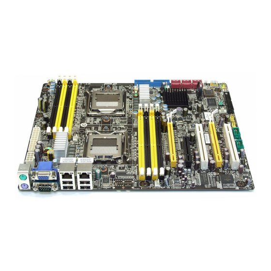
- Page 1 K9ND Speedster MS-9652 (V1.X) Server Board G52-96521X1...
-
Page 2: Trademarks
Alternatively, please try the following help resources for further guidance. Visit the MSI website at http://www.msi.com.tw/program/service/faq/ faq/esc_faq_list.php for FAQ, technical guide, BIOS updates, driver updates, and other information. Contact our technical staff at http://support.msi.com.tw/. -
Page 3: Safety Instructions
Safety Instructions Always read the safety instructions carefully. Keep this User’s Manual for future reference. Keep this equipment away from humidity. Lay this equipment on a reliable flat surface before setting it up. The openings on the enclosure are for air convection hence protects the equip- ment from overheating. -
Page 4: Fcc-B Radio Frequency Interference Statement
FCC-B Radio Frequency Interference Statement T h is eq uip men t h as been tested and found to c omply with the limits for a Class B digital device, pursuant to Part 15 of the FCC Rules. These limits are designed to provide reasonable protection against harmful interference in a residential installation. -
Page 5: Weee (Waste Electrical And Electronic Equipment) Statement
WEEE (Waste Electrical and Electronic Equipment) Statement... -
Page 8: Table Of Contents
CONTENTS Copyright Notice ......................ii Trademarks ........................ii Revision History ......................ii Technical Support ......................ii Safety Instructions ......................iii FCC-B Radio Frequency Interference Statement ............iv W EEE (Waste Electrical and Electronic Equipment) Statement ........v Chapter 1 Getting Started ..................1-1 Mainboard Specifications ................... - Page 9 IEEE 1394 Connectors: J1394_1, J1394_2 (Optional) ......2-17 Jumper ........................ 2-18 BIOS Recovery Jumper: J4 ..............2-18 Clear CMOS Jumper: JBAT1 ..............2-18 Slot ........................2-19 PCI (Peripheral Component Interconnect) Slot ........2-19 PCI Interrupt Request Routing ..............2-19 PCI Express Card Installation ..............2-20 Chapter 3 BIOS Setup .....................
- Page 10 Rebuilding a RAID Array ................A-22 Synchronizing a RAID Array ..............A-25 Usind Disk Alert ..................A-26 Appendix B Realtek ALC888 Audio ..............B-1 Installing the Realtek HD Audio Driver ..............B-2 Installation for W indows 2000/XP .............. B-2 Software Configuration ..................B-4 Sound Effect ....................
-
Page 11: Chapter 1 Getting Started
Getting Started Chapter 1 Getting Started Thank you for choosing the K9ND Speedster (MS-9652 v1.X), an excellent ATX server board from MSI. Based on the innovative nVIDIA MCP55 Pro chipset for optimal system efficiency, the K9ND Speedster ac- ® commodates the latest AMD... -
Page 12: Mainboard Specifications
MS-9652 Server Board Mainboard Specifications Proce ssor - Supports dual AMD Opteron (Socket F 1207) - HyperTransport interface capable of operating up to 2000 MT/s - Meets thermal requirements Chipset - nVIDIA nForce Professional 3600 MCP (MCP55 Pro ) M e mo r y - Supports ECC Registered DDR2 400/533/667 DIMMs - 8 DDR2 DIMM slots up to 16GB memory - 1-channel bus master IDE port... - Page 13 - 1 PCI-Express x16 slot (PCI_E1 supports x8 signal) - 1 PCI-Express x8 slot (PCI_E2 supports x4 signal) - 2 PCI slots Form Factor - ATX form factor 12” x 10.2” M ounting - 9 mounting holes For more information on compatible components, please visit http://www.msi.com.tw/program/products/server/svr/pro_svr_qvl.php...
-
Page 14: Mainboard Layout
AL C888 MCP55 Pro PCI_E2 PCI2 PCI_E1 VIA VT6308P SYS_FAN2 X GI PCI1 SYS_FAN3 J FP 1 JU SB 1 JU SB 2 J1394_2 J1394_1 CO M2 JFP 2 FLOP PY 1 K9ND Speedster (MS-9652 v1.X) ATX Server Board... -
Page 15: Chapter 2 Hardware Setup
Hardware Setup Chapter 2 Hardware Setup This chapter provides you with the information about hardware setup procedures. While doing the installation, be careful in holding the components and follow the installation procedures. For some components, if you install in the wrong orientation, the components will not work properly. -
Page 16: Quick Components Guide
MS-9652 Server Board Quick Components Guide Back Panel JPWR1, p.2-10 I/O, p.2-11 DIMM Slots, p.2-8 JPWR2, p.2-10 SYS_FAN1, p.2-14 CPU1_FAN1, p.2-14 CPU, p.2-3 CPU0_FAN1, p.2-14 IDE1, p.2-12 DIMM Slots, p.2-8 SYS_FAN4, p.2-14 JBAT1, p.2-18 P C I - C l a s s CHA_FAN1, Slots, p.2-19 p.2-14... -
Page 17: Cpu (Central Processing Unit)
W hen you are installing the CPU, make sure that you install the cooler to prevent the CPU from overheating. If you do not have the CPU cooler, contact your dealer to purchase and install it before turning on the computer. For the latest information about CPU, please visit http://www.msi.com.tw/program/ products/server/svr/pro_svr_qvl.php. Important 1. -
Page 18: Precautions For Thermal Issues
MS-9652 Server Board Precautions for thermal issues To virtually eliminate thermal issues, users are advised to take proper precautions. 1. Users are recommended to use AVC Z7UB408*** series cooler when installing 120W AMD Opteron CPU. 2. Users are recommended to use AVC Z8UB009*** series cooler when installing 95W AMD Opteron CPU. -
Page 19: Hardware Setup
Hardware Setup 3. W hen choosing the system chassis, make sure that its system fan is located adjacent to the MCP55 Pro chipset. This way, the system fan will contribute a lot to the heat dissipation of the chipset and PCI interface cards. 4. -
Page 20: Socket 1207 Cpu & Cooler Installation
MS-9652 Server Board Socket 1207 CPU & Cooler Installation 1. Locate the first CPU socket. (The CPU has a plastic cap on it to protect the contact from damage. Before installing the CPU, always cover it to protect the socket pins.) 2. - Page 21 Hardware Setup 7. Cover the load plate onto the package. 8. Press down the load lever lightly onto the load plate and then secure the lever with the hook under the retention tab. 9. Place the cooler set on top of the reten- tion mechanism.
-
Page 22: Memory
MS-9652 Server Board Memory The mainboard supports up to 8 Registered ECC DDR2 400/533/667 DIMM slots to provide the maximum of 16GB memory capacity. For more information on compatible components, please visit http://www.msi.com. tw/program/products/server/svr/pro_svr_qvl.php. DDR2 240-pin, 1.8V 64x2=128 pin 56x2=112 pin... -
Page 23: Memory Frequency Vs. Core Multiplier
Hardware Setup Memory Frequency vs. Core Multiplier The DDR2 DIMM operates different frequency when using different CPU. For example, when using 2.4GHz CPU the DDR2 667MHz DIMM will operate at 600MHz. Installing DDR2 Modules 1. The memory module has only one notch on the center and will only fit in the right orientation. -
Page 24: Power Supply
MS-9652 Server Board Power Supply 24-Pin System Power Connector: JPWR1 This connector allows you to connect to an SSI power supply. To connect to the power supply, make sure the plug of the power supply is inserted in the proper orientation and the pins are aligned. -
Page 25: Back Panel
Hardware Setup Back Panel Line-In RS-Out LAN1 LAN2 VGA Port M ou se Line-Out CS-Out M IC SPDIF-Out Keyboard Serial Port USB Ports USB Ports M ouse/Keyboard Connector ® ® The standard PS/2 mouse/keyboard DIN connector is for a PS/2 mouse/keyboard. -
Page 26: Connectors
MS-9652 Server Board Connectors Floppy Disk Drive Connector: FLOPPY1 The mainboard provides a standard floppy disk drive connector. FLOPPY1 IDE Connector: IDE1 The mainboard has a 32-bit Enhanced PCI IDE and Ultra DMA 66/100/133 controller that provides PIO mode 0~4, Bus Master, and Ultra DMA 66/100/133 function. You can connect hard disk drives, CD-ROM and other IDE devices. -
Page 27: Serial Ata Connector: Sata_1 ~ Sata_6
Hardware Setup Serial ATA Connector: SATA_1 ~ SATA_6 These connectors are high-speed SATA II interface ports and support SATA II data rates of 300MB/s. Each SATA II connector can connect to 1 hard disk device and is fully compliant with Serial ATA 2.0 specifications. SATA_5 SATA_6 SATA_3... -
Page 28: Cha_Fan1
MS-9652 Server Board LAN LED Connectors: LAN_LINK1, LAN_LINK2 The LAN LED connectors are used to connect to LAN LEDs, which show the activity of the LAN. The LAN_LINK1 is for the LAN 1 jack and the LAN_LINK2 is for the LAN2 jack. -
Page 29: Serial Port Connector: Com 2
Hardware Setup Serial Port Connector: COM 2 The mainboard provides one 9-pin header as serial port COM 2. The port is a 16550A high speed communication port that sends/receives 16 bytes FIFOs. You can attach a serial mouse or other serial devices directly to it. Pin Definition SIGNAL DESCRIPTION... -
Page 30: Front Panel Connectors: Jfp1, Jfp2
MS-9652 Server Board Front Panel Connectors: JFP1, JFP2 These connectors are for electrical connection to the front panel switches and LEDs. ® The JFP1 is compliant with Intel Front Panel I/O Connectivity Design Guide. JFP1 Power LED Power JFP2 Power Reset Switch Switch... -
Page 31: Chassis Intrusion Switch Connector: J1
Hardware Setup Chassis Intrusion Switch Connector: J1 This connector connects to a 2-pin chassis switch. If the chassis is opened, the switch will be short. The system will record this status and show a warning mes- sage on the screen. To clear the warning, you must enter the BIOS utility and clear the record. -
Page 32: Jumper
MS-9652 Server Board Jumper BIOS Recovery Jumper: J4 A "boot block" program is included as part of the system BIOS to recover the system from a situation when the BIOS code is incorrect/corrupted or needs to be updated. W hen the BIOS code is corrupted or needs to be updated, you have to at first enable the boot block by short connecting pin#2-3 of the J4 jumper. -
Page 33: Slot
Hardware Setup Slot PCI (Peripheral Component Interconnect) Slot The PCI-class slots support LAN cards, SCSI cards, USB cards, VGA cards, and other add-on cards that comply with PCI specifications. PCI Express architecture provides a high performance I/O infrastructure for Desktop Platforms with transfer rates starting at 2.5 Giga transfers per second over a PCI Express x1 lane for Gigabit Ethernet, TV Tuners, 1394 controllers, and general pur- pose I/O. -
Page 34: Pci Express Card Installation
MS-9652 Server Board PCI Express Card Installation 1. Locate the expansion slot you plan to use for your graphics card. 2. Gently insert the card into the expan- sion slot and firmly press it into place. 3. To remove the graphics card, first release the locking mechanism with a screw- driver (as indicated below) and simultaneously pull up the graphics card. -
Page 35: Chapter 3 Bios Setup
BIOS Setup Chapter 3 BIOS Setup This chapter provides information on the BIOS Setup program and allows you to configure the system for optimum use. You may need to run the Setup program when: ² An error message appears on the screen during the system booting up, and requests you to run SETUP. -
Page 36: Entering Setup
MS-9652 Server BoardB Entering Setup Power on the computer and the system will start POST (Power On Self Test) process. W hen the message below appears on the screen, press <F2> key to enter Setup. Press F2 to enter SETUP If the message disappears before you respond and you still wish to enter Setup, restart the system by turning it OFF and On or pressing the RESET button. -
Page 37: Control Keys
BIOS Setup Control Keys Function General Help window <F1> or <Alt-H> Exit this menu <Esc> Select a different menu arrow keys Move cursor up and down arrow keys Move cursor to top or bottom of window <Home> or <End> Move cursor to next or previous page <PgUp>... -
Page 38: The Menu Bar
MS-9652 Server BoardB The Menu Bar Once you enter PhoenixBIOS Setup Utility, the Main Menu will appear on the screen. On the Main Menu screen, you will see basic BIOS settings including system time & date, and the setup categories the BIOS supplies. Use Arrow keys to move among the items and menus, and make changes to the settings. - Page 39 BIOS Setup Main The items inside the Main menu are for basic system information and configuration. Each item includes none, one or more setup items. Use the Up/Down arrow keys or <Tab> to highlight the item or field you want to modify and use the <+> or <-> key to switch to the value you prefer.
- Page 40 MS-9652 Server BoardB [LBA Mode Control] Enabling LBA causes Logical Block Ad- dressing to be used in place of Cylinders, Heads and Sectors [32-Bit I/O] Enables 32-bit communication between CPU and IDE card [Tranfer Mode] Selects the method for transferring the data between the hard disk and system memory [Ultra DMA Mode] Indicates the type of Ultra DMA...
-
Page 41: Advanced
BIOS Setup Advanced Items in the menu are divided into several sub-menus. Each sub-menu provides more settings. To enter the sub-menu, highligh the sub-menu you want to configure and press <Enter>. Installed O/S W hen multiple operating systems are installed in your system, use this setting to select the major operating system that will be used most commonly. - Page 42 MS-9652 Server BoardB NumLock This setting is to set the Num Lock status when the system is powered on. Setting to [On] will turn on the Num Lock key when the system is powered on. Setting to [Off] will allow users to use the arrow keys on the numeric keypad. M emory Controller Options DRAM Bank Interleave Interleaved memory is system memory divided into two or more sections.
- Page 43 BIOS Setup see all of the (64-bit addressed) main memory although with a 32-bit address bus you can only address a 32-bit address space. It is a MMU that translates DMA virtual addresses to real physical addresses. Size This setting specifies the memory size for IOMMU. ACPI SRAT Table The Static Resource Affinity Table (SRAT) can be used to describe the physical location of processors and memory in large-scale systems (such as CC-NUMA)
- Page 44 MS-9652 Server BoardB ECC Scrub Redirection This setting enables/disables ECC Scrubber to correct errors detected in DRAM during normal CPU requests (foreground scrubbing). DRAM ECC Scrub Control The DRAM ECC Scrub option controls the frequency at which memory read options are corrected while the system is in an idle state. DCache ECC Scrub Control The Data Cache ECC Scrub option controls the time allotted for the L1 memory cache to be corrected when in an idle state.
- Page 45 BIOS Setup System Health These items display the current status of all of the monitored hardware devices/ components such as CPU voltages, temperatures and all fans’ speeds. CPU and System Voltage This field shows the CPU and system voltages. 3-11...
- Page 46 MS-9652 Server BoardB CPU and System Fan Speed These items display the current fans’ speeds of the system. Auto Fan Speed Control This item enables/disables the Smart Fan feature. Smart Fan is an excellent feature which will adjust the CPU/system fan speed automatically depending on the current CPU/system temperature, avoiding system damage caused by overheating.
- Page 47 BIOS Setup Integrated Devices USB Control This setting enables/disables the onboard USB host controller. USB BIOS Legacy Support Set to [Enabled] if your need to use any USB 1.1/2.0 device in the operating system that does not support or have any USB 1.1/2.0 driver installed, such as DOS and SCO Unix.
- Page 48 MS-9652 Server BoardB NV RAID Configuration NV RAID Configuration This setting enables/disables the nVIDIA software RAID configuration. 3-14...
- Page 49 BIOS Setup FirstWare Configuration FirstWare Language This setting allows you to change the screen language for your FirstW are applications. FirstWare Authentication Level This setting allows you to select the authentication level for your FirstW are applications. FirstWare Video Mode This setting allows you to change the video resolution for your FirstW are applications.
- Page 50 MS-9652 Server BoardB PCI Configuration MAC LAN, M AC1 LAN, PCI Device SATA, Onboard VGA Option ROM Scan Use this feature to initialize device expansion ROM. Enable Master W hen set to [Enabled], BIOS will activate the selected device as a PCI bus master.
- Page 51 BIOS Setup Floppy Configuration Legacy Diskette A: This setting allows you to set the type of floppy drives installed. Floppy Check This setting causes the BIOS to search for floppy disk drives at boot time. W hen enabled, the BIOS will activate the floppy disk drives during the boot process. 3-17...
- Page 52 MS-9652 Server BoardB I/O Device Configuration Serial Port A/B These settings enable/disable the onboard Serial Port A / B. Base I/O Address These settings specify the base I/O port addresses of the onboard Serial Port A / B. Interrupt These settings specify IRQs for the Serial Port A / B. Floppy Disk Controller This setting enables/disables the onboard floppy disk controller.
- Page 53 BIOS Setup Console Redirection Com Port Address This setting enables/disables the Com port address for console connection. Baud Rate This setting specifies the transfer rate (bits per second) of Console Redirection. Console Type This setting specifies the console type. Flow Control This feature allows you to enable flow control.
- Page 54 MS-9652 Server BoardB DM I Event Logging Event Log Capacity/Validity These items indicate the status of Event log validity and capacity. View DMI Event Log Press [Enter] to view the contents of the DMI event log. Clear All DMI Event Logs W hen this setting is set to [Yes], the DMI event log will be cleared at next POST stage.
-
Page 55: Power
BIOS Setup Power Use this menu to specify your settings for Power Management. Remember that the options available depend upon the hardware installed in your system. Power Loss Control This setting specifies whether your system will reboot after a power failure or interrupt occurs. - Page 56 MS-9652 Server BoardB Resume On Time Select [On] to wake up the system at predetermined time. Resume Time The time format is <HH> <MM> <SS>. Resume Date The date format is <MM> <DD> <YYYY>. ACPI Suspend Support This item specifies the power saving modes for ACPI function. If your operating system supports ACPI, you can choose to enter the Standby mode in S1 (POS) or S3 (STR) fashion through the setting of this field.
-
Page 57: Boot
BIOS Setup Boot Use this menu to arrange and specify the priority of the devices from which the BIOS will attempt to boot the Operating System. Boot Priority Order This setting allows users to set the boot priority of the specified devices. Refer to the Item Specific Help on the right pane for instructions. -
Page 58: Exit
MS-9652 Server BoardB Exit The following sections describe each of the options on this menu. Note that <Esc> does not exit this menu. You must select one of the items from the menu or menu bar to exit. Exit Saving Changes W hen you want to quit the Setup menu, you can select this option to save the changes and quit. -
Page 59: Appendix A Nvidia Sata Raid
nVIDIA SATA RAID Appendix A nVIDIA SATA RAID NVIDIA brings Redundant Array of Independent Disks (RAID) technology—which is used by the world’s lead- ing businesses—to the common PC desktop. This tech- nology uses multiple drives to either increase total disk space or to offer data protection. -
Page 60: Introduction
MS-9652 Server Board Introduction System Requirement Operating System Support NVRAID supports the following operating systems: W indows XP W indows 2003 x64 W indows 2003 W indows 2000 Professional W indows 2000 RAID Arrays NVRAID supports the following types of RAID arrays described in this section: RAID 0: RAID 0 defines a disk striping scheme that improves the disk read and write times for many applications. -
Page 61: Raid Configuration
nVIDIA SATA RAID RAID Configuration Basic Configuration Instructions The following are the basic steps for configuring NVRAID: Non-Bootable RAID Array 1. Choose the hard disks that are to be RAID enabled in the system BIOS. (To enable the nVidia RAID Function in nVidia RAID Setup of Integrated Peripherals in BIOS.) 2. - Page 62 MS-9652 Server Board Understanding the “Define a New Array” Window Use the Define a New Array window to • Select the RAID Mode • Set up the Striping Block • Specify which disks to use for the RAID Array Depending on the platform used, the system can have one or more channels. In a typical system there is usually one controller and multiple channels, and each chan- nel has a slave and a master.
- Page 63 nVIDIA SATA RAID Using the Define a New Array Window If necessary, press the tab key to move from field to field until the appropriate field is highlighted. • Selecting the RAID Mode By default, this is set to [Mirroring]. To change to a different RAID mode, press the down arrow key until the mode that you want appears in the RAID Mode box—either [Mirroring], [Striping].
- Page 64 MS-9652 Server Board Completing the RAID BIOS Setup 1. After assigning your RAID array disks, press F7. The Clear disk data prompt appears. 2. Press Y if you want to wipe out all the data from the RAID array, otherwise press N.
-
Page 65: Installing The Raid Driver (For Bootable Raid Array
Please follow the instructions below to make an nVIDIA Serial ATA RAID driver diskette for yourself. 1. Insert the MSI CD into the CD-ROM drive. 2. Click the “Browse CD” on the Setup screen. 3. Copy all the contents in the :... - Page 66 MS-9652 Server Board 4. Press Enter to continue with W indows XP Installation. Be sure to leave the floppy disk inserted in the floppy drive until the blue screen portion of W indows XP installation is completed, then take out the floppy. 5.
-
Page 67: Nvidia Raid Utility Installation
nVIDIA SATA RAID NVIDIA RAID Utility Installation Installing the NVIDIA RAID Software Under Windows (for Non- bootable RAID Array) The existing W indows IDE Parallel ATA driver (as well as the Serial ATA driver if SATA is enabled) must be upgraded to use the NVIDIA IDE Parallel ATA driver (as well as the NV Serial ATA driver if SATA is enabled). -
Page 68: Initializing And Using The Disk Array
MS-9652 Server Board Initializing and Using the Disk Array The RAID array is now ready to be initialized under W indows. 1. Launch Computer Management by clicking “Start” --> “Settings” --> “Control Panel” then open the “Administrative Tools” folder and double click on “Computer Management”. - Page 69 nVIDIA SATA RAID 5. Check the disk in the list if you want to make the array a dynamic disk, then click Next. The Completing the Initialize and Convert Disk W izard window appears. 6. Click Finish. The “Computer Management” window appears. The actual disks listed will depend on your system, and the unallocated partition is the total combined storage of two hard disks.
-
Page 70: Raid Drives Management
MS-9652 Server Board RAID Drives Management There is an application called NVRAIDMAN which helps you perform the following tasks of nVDIA RAID. • Viewing RAID Array Configurations View an array configuration (mirrored or striped) • Setting Up a Spare RAID Disk •... -
Page 71: Setting Up A Spare Raid Disk
nVIDIA SATA RAID Setting Up a Spare RAID Disk You can designate a hard drive to be used as a spare drive for a RAID 1 array. The spare drive can take over for a failed disk. NVRAID supports two types of spare drives: •... - Page 72 MS-9652 Server Board Assigning a Dedicated Disk To mark a disk as dedicated, or reserve it for use by a specific array, Step 1: Mark the Disk as a Free Disk 1. Enter the system BIOS setup and make sure that the drive that you want to mark as free is RAID enabled.
- Page 73 nVIDIA SATA RAID 3. Click Next. The RAID Array Selection page appears. 4. From the Free Disk Selection page, select one of the two free disks available. This would be the disk that will be designated to the mirror array. 5.
- Page 74 MS-9652 Server Board Removing a Dedicated Disk Once a dedicated disk has been assigned to a particular array, it can be removed at any time. To remove the disk, right click on the dedicated disk and select “Remove Disk...” to remove it. In the previous example, simply right click on the ST380011A drive and select “Remove Disk...”.
-
Page 75: Morphing From One Raid Array To Another
nVIDIA SATA RAID Morphing From One RAID Array to Another In a traditional RAID environment, when a user wants to change the current state of a disk or a current array to a new RAID configuration, the process of reconfiguring the new array involves multiple steps. -
Page 76: Hot Plug Array
MS-9652 Server Board Hot Plug Array W ith respect to RAID, hot plugging is the ability to add a disk to a system safely and without causing problems for the RAID software. For example, when a drive in a mirrored array fails, the user can launch the Hot Plug Array W izard which instructs the user as to when a drive can be safely added to the system. -
Page 77: Initializing A Raid Array
nVIDIA SATA RAID 3 Connect the RAID disk that you want to use with any given RAID array. 4 Click Next and the following screen shot will appear: 5 Click Finish. Initializing a RAID Array Initializing a RAID array erases all the data that is stored on that array, and writes all zeros to the disks. - Page 78 MS-9652 Server Board 2 The Create Array W izard opens. Follow the W izard to create a Mirror array. 3 At the Create Array W izard Welcome screen, click Next. 4 At the RAID Array Selection page, make sure that RAID Mode is set to “Mirroring” and Stripe Size is set to its default value of 64K, then click Next.
- Page 79 nVIDIA SATA RAID 9 Click Next, then click Finish at the Completing the NVIDIA Create Array W izard screen. The NVRAIDMAN windows shows the created RAID array as shown below. The Initialization Process As you can see from the screen shot above, the initialization process has started and it will be completed in a short period of time.
-
Page 80: Rebuilding A Raid Array
MS-9652 Server Board Rebuilding a RAID Array Rebuilding is the process of restoring data to a hard drive from other drives in the array. This applies only to fault tolerant arrays such as RAID 1. For example, assum- ing you have a two disk RAID 1 array, and one of the drives fail, then you need the lost data on the newly added drive. - Page 81 nVIDIA SATA RAID 4. Click Next. The Disk Selection page appears. 5. Select the drive that you want to rebuild by clicking it from the list, then click Next. The Completing the NVIDIA Rebuild Array page appears. 6. Click Finish. The array rebuilding starts after a few seconds, and a small pop-up message appears towards the bottom right corner of the screen as shown in the figure below.
- Page 82 MS-9652 Server Board During the rebuilding process, the NVRAID Management utility screen shows the status under the System Tasks and Details sections. M ore About Rebuilding Arrays • Rebuilding Occurs in the Background The rebuilding process is very slow (it can take up to a day) and occurs in the background so as not to affect the performance of the system.
-
Page 83: Synchronizing A Raid Array
nVIDIA SATA RAID Synchronizing a RAID Array Synchronizing an array will force a rebuild of redundancy or parity. The operation is applicable to any fault tolerant array such as RAID 1. • For RAID1, “sync” results in copying the data to the redundancy disk, To sync an array, do the following (This example assumes you have already created a fault tolerant array such as RAID 1): 1 Right click on “Mirroring”... -
Page 84: Usind Disk Alert
MS-9652 Server Board Usind Disk Alert The RAID manager application includes a disk alert feature that provides a graphical indication of the status of the hard disks in the system. W hen the RAID manager application detects a failure condition of an attached drive, a pop-up box appears in the clock area of the W indows system tray. -
Page 85: Appendix B Realtek Alc888 Audio
Realtek ALC888 Audio Appendix B Realtek ALC888 Audio The Realtek ALC888 provides 10-channel DAC that si- multaneously supports 7.1 sound playback and 2 chan- nels of independent s tereo s ound output (multiple streaming) through the Front-Out-Left and Front-Out- Right channels. -
Page 86: Installing The Realtek Hd Audio Driver
MS-9652 Server Board Installing the Realtek HD Audio Driver You need to install the driver for Realtek ALC888 codec to function properly before you can get access to 2-, 4-, 6-, 8- channel or 7.1+2 channel audio operations. Follow the procedures described below to install the drivers for different operating systems. - Page 87 Realtek ALC888 Audio 3. Click Next to install the Realtek High Definition Audio Driver. Click here 4. Click Finish to restart the system. S el ec t t hi s option Click here...
-
Page 88: Software Configuration
MS-9652 Server Board Software Configuration After installing the audio driver, you are able to use the 2-, 4-, 6- or 8- channel audio feature now. Click the audio icon from the system tray at the lower-right corner of the screen to activate the HD Audio Configuration. It is also available to enable the audio driver by clicking the Realtek HD Audio M anager from the Control Panel. -
Page 89: Sound Effect
Realtek ALC888 Audio Sound Effect Here you can select a sound effect you like from the Environment list. Environment Simulation You will be able to enjoy different sound experience by pulling down the arrow, totally 23 kinds of sound effect will be shown for selection. Realtek HD Audio Sound Manager also provides five popular settings “... - Page 90 MS-9652 Server Board Equalizer Selection Equalizer frees users from default settings; users may create their owned preferred settings by utilizing this tool. 10 bands of equalizer, ranging from 100Hz to 16KHz. Save Reset The settings are saved 10 bands of equalizer permanently for future would go back to the de- fault setting...
- Page 91 Realtek ALC888 Audio Frequently Used Equalizer Setting Realtek recognizes the needs that you might have. By leveraging our long experience at audio field, Realtek HD Audio Sound Manager provides you certain optimized equal- izer settings that are frequently used for your quick enjoyment. [How to Use It] Other than the buttons “Pop”...
-
Page 92: Mixer
MS-9652 Server Board Mixer In the Mixer part, you may adjust the volumes of the rear and front panels individually. 1. Adjust Volume You can adjust the volume of the speakers that you pluged in front or rear panel by select the Realtek HD Audio rear output or Realtek HD Audio front output items. - Page 93 Realtek ALC888 Audio W hen you are playing the first audio source (for example: use W indows Media Player to play DVD/VCD), the output will be played from the rear panel, which is the default setting. Then you must to select the Realtek HD Audio front output from the scroll list first, and use a different program to play the second audio source (for example: use Winamp to play MP3 files).
- Page 94 MS-9652 Server Board 3. Playback control Playback device Tool Mute This function is to let you freely decide which ports to output the sound. And this is essential when multi- streaming playback enabled. - Realtek HD Audio Rear Output - Realtek HD Audio Front Output M u te You may choose to mute single or multiple volume controls or to completely mute sound output.
- Page 95 Realtek ALC888 Audio 4. Recording control Recording device Tool Mute -Back Line in/Mic, Front Lin in -Realtek HD Audio Input M u te You may choose to mute single or multiple volume controls or to completely mute sound input. Tool - Show the following volume controls This is to let you freely decide which volume control items to be displayed.
-
Page 96: Audio I/O
MS-9652 Server Board Audio I/O In this tab, you can easily configure your multi-channel audio function and speakers. You can choose a desired multi-channel operation here. a. Headphone for the common headphone b. 2CH Speaker for Stereo-Speaker Output c. 4CH Speaker for 4-Speaker Output d. - Page 97 Realtek ALC888 Audio Connector Settings Click to access connector settings. Disable front panel jack detection (option) Find no function on front panel jacks? Please check if front jacks on your system are so-called AC’97 jacks. If so, please check this item to disable front panel jack detection. M ute rear panel output when front headphone plugged in.
- Page 98 MS-9652 Server Board S/PDIF Short for Sony/Philips Digital Interface, a standard audio file transfer format. S/PDIF allows the transfer of digital audio signals from one device to another without having to be converted first to an analog format. Maintaining the viability of a digital signal prevents the quality of the signal from degrading when it is converted to analog.
- Page 99 Realtek ALC888 Audio Test Speakers You can select the speaker by clicking it to test its functionality. The one you select will light up and make testing sound. If any speaker fails to make sound, then check whether the cable is inserted firmly to the connector or replace the bad speakers with good ones.
-
Page 100: Microphone
MS-9652 Server Board Microphone In this tab you may set the function of the microphone. Select the Noise Suppres- sion to remove the possible noise during recording, or select Acoustic Echo Cancelltion to cancel the acoustic echo druing recording. Acoustic Echo Cancelltion prevents playback sound from being recorded by mi- crophone together with your sound. -
Page 101: 3D Audio Demo
Realtek ALC888 Audio 3D Audio Demo In this tab you may adjust your 3D positional audio before playing 3D audio applica- tions like gaming. You may also select different environment to choose the most suitable environment you like. B-17... -
Page 102: Information
MS-9652 Server Board Information In this tab it provides some information about this HD Audio Configuration utility, including Audio Driver Version, DirectX Version, Audio Controller & Audio Codec. You may also select the language of this utility by choosing from the Language list. Also there is a selection Show icon in system tray. -
Page 103: Hardware Setup
Realtek ALC888 Audio Hardware Setup Connecting the Speakers W hen you have set the Multi-Channel Audio Function mode properly in the software utility, connect your speakers to the correct phone jacks in accordance with the setting in software utility. n 2-Channel M ode for Stereo-Speaker Output Back Panel Line In Line Out (Front channels) - Page 104 MS-9652 Server Board n 4-Channel M ode for 4-Speaker Output Back Panel Description: Connect two speakers to back panel’s Line Out connector and two speakers to the real-chan- nel Line Out connector. 4-Channel Analog Audio Output Line In Line Out (Front channels) Line Out (Rear channels) Line Out (Center and Subwoofer channel, but not functioning in this mode) S/PDIF Out-Optical...
- Page 105 Realtek ALC888 Audio n 6-Channel M ode for 6-Speaker Output Back Panel Description: Connect two speakers to back panel’s Line Out connector, two speakers to the rear-channel Line out connec tor and two s p e a k e r s t o t h e c e n t e r / subwoofer-channel Line Out 6-Channel Analog Audio Output connector.
- Page 106 MS-9652 Server Board n 8-Channel M ode for 8-Speaker Output Back Panel Description: Connect two speakers to back panel’s Line Out connector, two speakers to the rear-channel Line out connector, two speak- ers to the center/subwoofer- channel Line Out connector and 8-Channel Analog Audio Output two speakers to the side-chan- nel Line Out connector.
Need help?
Do you have a question about the K9ND Speedster and is the answer not in the manual?
Questions and answers