Table of Contents
Advertisement
Advertisement
Table of Contents

Subscribe to Our Youtube Channel
Related Manuals for MSI K9NU Speedster


Summary of Contents for MSI K9NU Speedster
- Page 1 K9NU Speedster MS-9655 (V2.X) Server Board G52-96551X1...
-
Page 2: Trademarks
If a problem arises with your system and no solution can be obtained from the user’s manual, please contact your place of purchase or local distributor. Alternatively, please try the following help resources for further guidance. Vis i t the MSI webs ite at http ://glob al.msi. com.tw /index. php? func=faqIndex for FAQ, technical guide, BIOS updates, driver updates, and other information. -
Page 3: Safety Instructions
Safety Instructions Always read the safety instructions carefully. Keep this User’s Manual for future reference. Keep this equipment away from humidity. Lay this equipment on a reliable flat surface before setting it up. The openings on the enclosure are for air convection hence protects the equip- ment from overheating. -
Page 4: Fcc-B Radio Frequency Interference Statement
FCC-B Radio Frequency Interference Statement T h is eq uip men t h as been tested and found to c omply with the limits for a Class B digital device, pursuant to Part 15 of the FCC Rules. These limits are designed to provide reasonable protection against harmful interference in a residential installation. -
Page 5: Weee (Waste Electrical And Electronic Equipment) Statement
WEEE (Waste Electrical and Electronic Equipment) Statement... -
Page 8: Table Of Contents
CONTENTS Copyright Notice ......................ii Trademarks ........................ii Revision History ......................ii Technical Support ......................ii Safety Instructions ......................iii FCC-B Radio Frequency Interference Statement ............iv W EEE (Waste Electrical and Electronic Equipment) Statement ........v Chapter 1 Getting Started ..................1-1 Mainboard Specifications ................... -
Page 9: Chapter 1 Getting Started
Getting Started Chapter 1 Getting Started Thank you for choosing the K9NU Speedster (MS-9655 v2.X), an excellent ATX server board from MSI. Based on the innovative nVIDIA MCP55V Pro chipset for optimal system efficiency, the K9NU Speedster ac- ® commodates the latest AMD... -
Page 10: Mainboard Specifications
MS-9655 Server Board Mainboard Specifications Proce ssor - Supports single AMD Opteron (Socket F 1207) - HyperTransport interface capable of operating up to 2000 MT/s - Meets thermal requirements Chipset - nVIDIA nForce Professional 3400 MCP (MCP55V Pro) M e mo r y - Supports Registered ECC DDR2 400/533/667 DIMM slots - 8 DDR2 DIMM slots up to 32GB memory TE: When 1~4 DIMMs are installed, memory will run at 667MHz. - Page 11 Getting Started System M anagement - Renesas H8S/2168V IPMI microcontroller Connectors Back Panel - 1 x PS/2 mouse port - 1 x PS/2 keyboard port - 1 x serial port - 1 x VGA port - 2 x RJ-45 Gigabit LAN ports - 4 x USB ports - 1 x audio jack Onboard Pinheaders...
-
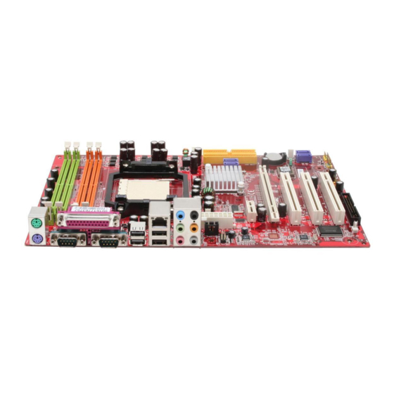
Page 12: Mainboard Layout
PCI _E3 BIOS SATA2 (optional) SATA1 (optional) PCI _E4 W inb ond FAN1 W 83627DHG PCI 1 FLO1 VT6308P J1394 PCI 2 IDE1 FPC1 SFAN3 JUSB2 J1394_1 J1394_2 JUSB1 COM2 JAPP 2 (optional) K9NU Speedster (MS-9655 v2.X) ATX Server Board... -
Page 13: Chapter 2 Hardware Setup
Hardware Setup Chapter 2 Hardware Setup This chapter provides you with the information about hardware setup procedures. While doing the installation, be careful in holding the components and follow the installation procedures. For some components, if you install in the wrong orientation, the components will not work properly. -
Page 14: Quick Components Guide
MS-9655 Server Board Quick Components Guide DIMM Slots, p.2-6 Back Panel I/O, p.2-10 JAPP1, JPWR1, p.2-9 p.2-19 SFAN1, p.2-14 CFAN1, p.2-14 J11, p.2-13 CPU, p.2-3 SASC2, p.2-12 JPWR2, p.2-9 JBAT1/J1, p.2-20/21 JCD1, p.2-16 SFAN2, p.2-14 JVGAD, p.2-21 JAUD1/ JAUD2, JAPP3, p.2-19 p.2-17 SATA1~6, p.2-13 P C I - C l a s s... -
Page 15: Cpu (Central Processing Unit)
Hardware Setup CPU (Central Processing Unit) ® This mainboard supports the latest AMD Opteron processor in 1207-pin package. W hen you are installing the CPU, make sure that you install the cooler to prevent the CPU from overheating. If you do not have the CPU cooler, contact your dealer to purchase and install it before turning on the computer. - Page 16 MS-9655 Server Board Socket 1207 CPU & Cooler Installation 1. Locate the first CPU socket. (The CPU has a plastic cap on it to protect the contact from damage. Before installing the CPU, always cover it to protect the socket pins.) 2.
- Page 17 Hardware Setup 7. Cover the load plate onto the package. 8. Press down the load lever lightly onto the load plate and then secure the lever with the hook under the retention tab. 9. Place the cooler set on top of the reten- tion mechanism.
-
Page 18: Memory
MS-9655 Server Board Memory These DIMM slots are intended for system memory modules. DDR2 240-pin, 1.8V 64x2=128 pin 56x2=112 pin Dual-Channel Mode Population Rule In Dual-Channel mode, the memory modules can transmit and receive data with two data bus lines simultaneously. Enabling Dual-Channel mode can enhance the system performance. - Page 19 Hardware Setup Memory Frequency vs. Core Multiplier The DDR2 DIMM operates different frequency when using different CPU. For example, when using 2.4GHz CPU the DDR2 667MHz DIMM will operate at 600MHz.
-
Page 20: Installing Memory Modules
MS-9655 Server Board Installing Memory Modules 1. The memory module has only one notch on the center and will only fit in the right orientation. 2. Insert the memory module vertically into the DIMM slot. Then push it in until the golden finger on the memory module is deeply inserted in the DIMM slot. -
Page 21: Power Supply
Hardware Setup Power Supply 24-Pin System Power Connector: JPWR1 This connector allows you to connect power supply. To connect to the power supply, make sure the plug of the power supply is inserted in the proper orientation and the pins are aligned. Then push down the power supply firmly into the connector. 12V Power Connector: JPWR2 This 12V power connector is used to provide power to the CPU. -
Page 22: Back Panel
MS-9655 Server Board Back Panel Mouse Line-In RS-Out Line-Out CS-Out Keyboard USB Ports Serial Port VGA Port Optical SPDIF-Out M ouse/Keyboard ® ® The standard PS/2 mouse/keyboard DIN connector is for a PS/2 mouse/keyboard. Serial Port The serial port is a 16550A high speed communications port that sends/ receives 16 bytes FIFOs. - Page 23 Hardware Setup Audio Ports (Optional) These audio connectors are used for audio devices. You can differentiate the color of the audio jacks for different audio sound effects. Line-In (Blue) - Line In / Side-Surround Out in 7.1 channel mode, is used f or external CD player, tapeplayer or other audio devices.
-
Page 24: Connectors
MS-9655 Server Board Connectors Floppy Disk Drive Connector: FLO1 This connector supports 360KB, 720KB, 1.2MB, 1.44MB or 2.88MB floppy disk drive. FLO1 IDE Connector: IDE1 This connector supports IDE hard disk drives, optical disk drives and other IDE devices. IDE1 Important If you install two IDE devices on the same cable, you must configure the drives separately to master / slave mode by setting jumpers. - Page 25 Hardware Setup SAS Connector: SASC1, SASC2 (Optional) These connectors are designed to connect Serial ATA devices only. SAS LED Connector: J10, J11 (Optional) These connectors are used to connect external LEDs to show the status of the SATA HDDs attached to the SASC1 & SASC2. The J10 is intended for the SASC1 and the J11 is made for the SASC2.
- Page 26 MS-9655 Server Board DVD/CD-ROM Connector: FPC1 (Optional) This connector is designed to connect slim DVD/CD-ROM drive. FPC1 Serial Port Connector: COM 2 This connector is a 16550A high speed communications port that sends/receives 16 bytes FIFOs. You can attach a serial device to it. Pin Definition SIGNAL DESCRIPTION...
- Page 27 Hardware Setup Front USB Connector: JUSB1, JUSB2 ® This connector, compliant with Intel I/O Connectivity Design Guide, is ideal for con- necting high-speed USB interface peripherals such as USB HDD, digital cameras, M P3 players, printers, modems and the like. JUSB1/2 Pin Definition SIGNAL...
- Page 28 MS-9655 Server Board CD-In Connector: JCD1 This connector is provided for external audio input. JCD1 IEEE1394 Connector: J1394_1, J1394_2 (Optional) This connector allows you to connect the IEEE1394 device via an optional IEEE1394 bracket. Pin Definition SIGNAL SIGNAL TPA+ TPA- J1394_1/J1394_2 Ground Ground...
- Page 29 Hardware Setup Chassis Intrusion Switch Connector: J2 This connector connects to the chassis intrusion switch cable. If the chassis is opened, the chassis intrusion mechanism will be activated. The system will record this status and show a warning message on the screen. To clear the warning, you must enter the BIOS utility and clear the record.
- Page 30 MS-9655 Server Board System Management Connector: J5, J6, J7, J8 These connectors are used to control the Renesas H8 Baseboard Management Controller (BMC). J5 Pin Definition J6 Pin Definition J8 Pin Definition SIGNAL SIGNAL SIGNAL H8_RESET Bode Mode IPMB_CLK IPMB_DATA J7 Pin Definition SIGNAL SIGNAL...
- Page 31 Hardware Setup Front Panel Connector: JAPP1, JAPP2, JAPP3 (Optional) These are proprietary front panel connectors that provide I C bus connection, serial signal connection, and electrical connection to the front panel switches/LEDs. JAPP1 Pin Definition SIGNAL SIGNAL JAPP1 +5VSB RESET+ POWER+ COM2 RXD COM2 TXD...
-
Page 32: Jumper
MS-9655 Server Board Jumper Clear CMOS Jumper: JBAT1 There is a CMOS RAM onboard that has a power supply from external battery to keep the data of system configuration. With the CMOS RAM, the system can automatically boot OS every time it is turned on. If you want to clear the system configuration, set this jumper to clear data. - Page 33 Hardware Setup VGA Jumper: JVGAD This jumper is used to enable or disable the onboard VGA controller. JVGAD Enable Disable IEEE1394 Jumper: J1394 This jumper is used to enable or disable the onboard IEEE1394 controller. J1394 Enable Disable BIOS Recovery Jumper: J9 Users can short connect pin#2-3 to recover the system BIOS.
-
Page 34: Slot
MS-9655 Server Board Slot PCI (Peripheral Component Interconnect) Express Slot The PCI Express slot supports the PCI Express interface expansion card. The PCI Express x 16 slot supports up to 4.0 GB/s transfer rate. The PCI Express x 1 slot supports up to 250 MB/s transfer rate. PCI Express x1 Slot PCI Express x16 Slot PCI (Peripheral Component Interconnect) Slot... -
Page 35: Chapter 3 Bios Setup
BIOS Setup Chapter 3 BIOS Setup This chapter provides information on the BIOS Setup program and allows you to configure the system for optimum use. You may need to run the Setup program when: ² An error message appears on the screen during the system booting up, and requests you to run SETUP. -
Page 36: Entering Setup
MS-9655 Server BoardB Entering Setup Power on the computer and the system will start POST (Power On Self Test) process. W hen the message below appears on the screen, press <F2> key to enter Setup. Press F2 to enter SETUP If the message disappears before you respond and you still wish to enter Setup, restart the system by turning it OFF and On or pressing the RESET button. -
Page 37: Control Keys
BIOS Setup Control Keys Function General Help window <F1> or <Alt-H> Exit this menu <Esc> Select a different menu arrow keys Move cursor up and down arrow keys Move cursor to top or bottom of window <Home> or <End> Move cursor to next or previous page <PgUp>... -
Page 38: The Menu Bar
MS-9655 Server BoardB The Menu Bar Main Use this menu for basic system configurations, such as time, date etc. Advanced Use this menu to set up the items of special enhanced features available on your system’s chipset. Security Use this menu to set Supervisor and User Passwords. Boot Use this menu to specify the priority of boot devices. -
Page 39: Main
BIOS Setup Main BIOS Date, BIOS Version These items show the information of the system BIOS. (Read-only) QuickBoot M ode Setting the item to [Enabled] allows the system to boot within 5 seconds since it will skip some check items. Summary Screen Select [Enabled] if you want to view the system summary screen. -
Page 40: Advanced
MS-9655 Server BoardB Advanced Installed O/S W hen multiple operating systems are installed in your system, use this setting to select the major operating system that will be used most commonly. Note that an incorrect setting in this field may cause unexpected errors on the operating systems. NOTE: When installing Linux OS, you must switch this item to [Linux]. - Page 41 BIOS Setup ing to update the BIOS with a Flash utility. To successfully update the BIOS, you’ll need to disable this BIOS W rite Protect function. You should enable this function at all times. The only time when you need to disable it is when you want to update the BIOS.
- Page 42 MS-9655 Server BoardB M emory Controller Options Max M em Clock Use this field to configure the highest clock frequency of the installed DRAM. Users may also assign a lower memory clock frequency here. DRAM Bank Interleave Interleaved memory is system memory divided into two or more sections. Set- ting to [Enabled] allows memory to be accessed faster since each section of memory is capable of being utilized at once.
- Page 43 BIOS Setup ACPI SRAT Table The Static Resource Affinity Table (SRAT) can be used to describe the physical location of processors and memory in large-scale systems (such as CC-NUMA) to the Microsoft W indows Server 2003 operating system, allowing threads and memory to be grouped in an optimal manner.
- Page 44 MS-9655 Server BoardB that protects servers from system downtime caused by memory failures. ECC Scrub Redirection This setting enables/disables ECC Scrubber to correct errors detected in DRAM during normal CPU requests (foreground scrubbing). DRAM ECC Scrub Control The DRAM ECC Scrub option controls the frequency at which memory read options are corrected while the system is in an idle state.
- Page 45 BIOS Setup MAC LAN, MAC 1 LAN These settings allow you to enable/disable the specified device controllers. Azalia Codec Azalia is the codename of “High Definition Audio.” This setting allows users to disable/enable the High Definition Audio interface integrated in the Southbridge. SATA0 Controller, SATA1 Controller, SATA2 Controller These settings allow you to enable/disable the onchip Serial-ATA controllers.
- Page 46 MS-9655 Server BoardB IDE Configuration Large Disk Access M ode Defaulting this setting to [DOS] will create a Translated FDPT. Compatible ill- behaved applications will operate correctly when [DOS] is selected. Setting to [Other] will create a Standard FDPT. Incompatible ill-behaved applications will function correctly with [Other].
- Page 47 BIOS Setup [Tranfer Mode] Selects the method for transferring the data between the hard disk and system memory [Ultra DMA Mode] Indicates the type of Ultra DMA Floppy Configuration Legacy Diskette A This setting allows you to set the type of floppy drives installed. Floppy Check This setting causes the BIOS to search for floppy disk drives at boot time.
- Page 48 MS-9655 Server BoardB I/O Device Configuration KBC Clock This BIOS feature allows you to adjust the keyboard interface clock for a better response or to fix a keyboard problem. It is recommended that you select a higher clock speed for a better keyboard response. But if the keyboard per- forms erratically or fails to initialize, try a lower clock speed.
- Page 49 BIOS Setup IPMI IPMI Specification Version Indicate the IPMI (Intelligent Platform Management Interface) version. BM C Hardware/Firmware Version Indicate the BMC (Baseboard Management Controller) version. Clear System Event Log This function is used to clear system event logs. Existing Event Log Number Indicates how many event logs are existing.
- Page 50 MS-9655 Server BoardB System Event Log This setting shows the real-time system event logs on the system monitor sens or. Dynamic or Static IP Config This setting is used to configure your dynamic (temporary) or static (permanent) network IP. Setting to [DHCP] (Dynamic Host Configuration Protocol) allows the network IP to be automatically assigned.
- Page 51 BIOS Setup Console Redirection Com Port Address This setting enables/disables the serial port address for console connection. Baud Rate This setting specifies the transfer rate (bits per second) of Console Redirection. Console Type This setting specifies the console type. Flow Control Flow control is the process of managing the rate of data transmission between two nodes.
- Page 52 MS-9655 Server BoardB DM I Event Logging Event Log Capacity/Validity These items indicate the status of Event log validity and capacity. View DMI Event Log Press [Enter] to view the contents of the DMI event log. Clear All DMI Event Logs W hen this setting is set to [Yes], the DMI event log will be cleared at next POST stage.
-
Page 53: Security
BIOS Setup Security Supervisor Password Is / User Password Is It shows the preset supervisor/user password. (read only) Set Supervisor Password / Set User Password Enabling Supervisor Password requires a password for entering Setup. The pass- words are not case sensitive. Pressing <Enter> at either Set Supervisor Password or Set User Password displays the following message: Set Supervisor Password Enter New Password:... -
Page 54: Boot
MS-9655 Server BoardB Boot Boot Priority Order This setting allows users to set the boot priority of the specified devices. Refer to the Item Specific Help on the right pane for instructions. Excluded from Boot Order This setting allows users to exclude the specified devices from the Boot Order list. 3-20... -
Page 55: Power
BIOS Setup Power Enable Cool’n’Quiet This feature is especially desiged for AMD Athlon processor, which provides a CPU temperature detecting function to prevent your CPU from overheading due to heavy workload. Spread Spectrum W hen the motherboard’s clock generator pulses, the extreme values (spikes) of the pulses creates EMI (Electromagnetic Interference). - Page 56 MS-9655 Server BoardB CPU/LDT, TGIO, SATA Spread Spectrum (Optional) These settings are used to enable/disable the Spread Spectrum feature for the specified target. W hen overclocking, always set them to [Disabled]. Enable M ultimedia Timer This setting enables the Multimedia Timer to achieve better resolution for multimedia and other time-sensitive applications.
-
Page 57: Exit
BIOS Setup Exit Exit Saving Changes W hen you want to quit the Setup menu, you can select this option to save the changes and quit. Exit Discarding Changes W hen you want to quit the Setup menu, you can select this option to abandon the changes. - Page 58 MS-9655 Server BoardB 3-24...
-
Page 59: Appendix A Nvidia Sata Raid
nVIDIA SATA RAID Appendix A nVIDIA SATA RAID NVIDIA brings Redundant Array of Independent Disks (RAID) technology—which is used by the world’s lead- ing businesses—to the common PC desktop. This tech- nology uses multiple drives to either increase total disk space or to offer data protection. -
Page 60: Introduction
Important Please note that the companion MSI Driver/Utility CD supports this mainboard with Windows 2000/XP system drivers ONLY. Hence, users cannot install OS, either WinME or Win98, in their SATA hard drives. -
Page 61: Raid Configuration
nVIDIA SATA RAID RAID Configuration Basic Configuration Instructions The following are the basic steps for configuring NVRAID: Non-Bootable RAID Array 1. Choose the hard disks that are to be RAID enabled in the system BIOS. (To enable the nVidia RAID Function in nVidia RAID Setup of Integrated Peripherals in BIOS.) 2. - Page 62 MS-9655 Server Board Understanding the “Define a New Array” Window Use the Define a New Array window to • Select the RAID Mode • Set up the Striping Block • Specify which disks to use for the RAID Array Depending on the platform used, the system can have one or more channels. In a typical system there is usually one controller and multiple channels, and each chan- nel has a slave and a master.
- Page 63 nVIDIA SATA RAID Using the Define a New Array Window If necessary, press the tab key to move from field to field until the appropriate field is highlighted. • Selecting the RAID Mode By default, this is set to [Mirroring]. To change to a different RAID mode, press the down arrow key until the mode that you want appears in the RAID Mode box—either [Mirroring], [Striping].
- Page 64 MS-9655 Server Board Completing the RAID BIOS Setup 1. After assigning your RAID array disks, press F7. The Clear disk data prompt appears. 2. Press Y if you want to wipe out all the data from the RAID array, otherwise press N.
- Page 65 Please follow the instructions below to make an nVIDIA Serial ATA RAID driver diskette for yourself. 1. Insert the MSI CD into the CD-ROM drive. 2. Click the “Browse CD” on the Setup screen. 3. Copy all the contents in the :...
- Page 66 MS-9655 Server Board 4. Press Enter to continue with W indows XP Installation. Be sure to leave the floppy disk inserted in the floppy drive until the blue screen portion of W indows XP installation is completed, then take out the floppy. 5.
-
Page 67: Nvidia Raid Utility Installation
nVIDIA SATA RAID NVIDIA RAID Utility Installation Installing the NVIDIA RAID Software Under Windows (for Non- bootable RAID Array) The existing W indows IDE Parallel ATA driver (as well as the Serial ATA driver if SATA is enabled) must be upgraded to use the NVIDIA IDE Parallel ATA driver (as well as the NV Serial ATA driver if SATA is enabled). -
Page 68: Initializing And Using The Disk Array
MS-9655 Server Board Initializing and Using the Disk Array The RAID array is now ready to be initialized under W indows. 1. Launch Computer Management by clicking “Start” --> “Settings” --> “Control Panel” then open the “Administrative Tools” folder and double click on “Computer Management”. - Page 69 nVIDIA SATA RAID 5. Check the disk in the list if you want to make the array a dynamic disk, then click Next. The Completing the Initialize and Convert Disk W izard window appears. 6. Click Finish. The “Computer Management” window appears. The actual disks listed will depend on your system, and the unallocated partition is the total combined storage of two hard disks.
-
Page 70: Raid Drives Management
MS-9655 Server Board RAID Drives Management There is an application called NVRAIDMAN which helps you perform the following tasks of nVDIA RAID. • Viewing RAID Array Configurations View an array configuration (mirrored or striped) • Setting Up a Spare RAID Disk •... -
Page 71: Setting Up A Spare Raid Disk
nVIDIA SATA RAID Setting Up a Spare RAID Disk You can designate a hard drive to be used as a spare drive for a RAID 1 array. The spare drive can take over for a failed disk. NVRAID supports two types of spare drives: •... - Page 72 MS-9655 Server Board Assigning a Dedicated Disk To mark a disk as dedicated, or reserve it for use by a specific array, Step 1: Mark the Disk as a Free Disk 1. Enter the system BIOS setup and make sure that the drive that you want to mark as free is RAID enabled.
- Page 73 nVIDIA SATA RAID 3. Click Next. The RAID Array Selection page appears. 4. From the Free Disk Selection page, select one of the two free disks available. This would be the disk that will be designated to the mirror array. 5.
- Page 74 MS-9655 Server Board Removing a Dedicated Disk Once a dedicated disk has been assigned to a particular array, it can be removed at any time. To remove the disk, right click on the dedicated disk and select “Remove Disk...” to remove it. In the previous example, simply right click on the ST380011A drive and select “Remove Disk...”.
-
Page 75: Morphing From One Raid Array To Another
nVIDIA SATA RAID Morphing From One RAID Array to Another In a traditional RAID environment, when a user wants to change the current state of a disk or a current array to a new RAID configuration, the process of reconfiguring the new array involves multiple steps. -
Page 76: Hot Plug Array
MS-9655 Server Board Hot Plug Array W ith respect to RAID, hot plugging is the ability to add a disk to a system safely and without causing problems for the RAID software. For example, when a drive in a mirrored array fails, the user can launch the Hot Plug Array W izard which instructs the user as to when a drive can be safely added to the system. -
Page 77: Initializing A Raid Array
nVIDIA SATA RAID 3 Connect the RAID disk that you want to use with any given RAID array. 4 Click Next and the following screen shot will appear: 5 Click Finish. Initializing a RAID Array Initializing a RAID array erases all the data that is stored on that array, and writes all zeros to the disks. - Page 78 MS-9655 Server Board 2 The Create Array W izard opens. Follow the W izard to create a Mirror array. 3 At the Create Array W izard Welcome screen, click Next. 4 At the RAID Array Selection page, make sure that RAID Mode is set to “Mirroring” and Stripe Size is set to its default value of 64K, then click Next.
- Page 79 nVIDIA SATA RAID 9 Click Next, then click Finish at the Completing the NVIDIA Create Array W izard screen. The NVRAIDMAN windows shows the created RAID array as shown below. The Initialization Process As you can see from the screen shot above, the initialization process has started and it will be completed in a short period of time.
-
Page 80: Rebuilding A Raid Array
MS-9655 Server Board Rebuilding a RAID Array Rebuilding is the process of restoring data to a hard drive from other drives in the array. This applies only to fault tolerant arrays such as RAID 1. For example, assum- ing you have a two disk RAID 1 array, and one of the drives fail, then you need the lost data on the newly added drive. - Page 81 nVIDIA SATA RAID 4. Click Next. The Disk Selection page appears. 5. Select the drive that you want to rebuild by clicking it from the list, then click Next. The Completing the NVIDIA Rebuild Array page appears. 6. Click Finish. The array rebuilding starts after a few seconds, and a small pop-up message appears towards the bottom right corner of the screen as shown in the figure below.
- Page 82 MS-9655 Server Board During the rebuilding process, the NVRAID Management utility screen shows the status under the System Tasks and Details sections. M ore About Rebuilding Arrays • Rebuilding Occurs in the Background The rebuilding process is very slow (it can take up to a day) and occurs in the background so as not to affect the performance of the system.
-
Page 83: Synchronizing A Raid Array
nVIDIA SATA RAID Synchronizing a RAID Array Synchronizing an array will force a rebuild of redundancy or parity. The operation is applicable to any fault tolerant array such as RAID 1. • For RAID1, “sync” results in copying the data to the redundancy disk, To sync an array, do the following (This example assumes you have already created a fault tolerant array such as RAID 1): 1 Right click on “Mirroring”... -
Page 84: Usind Disk Alert
MS-9655 Server Board Usind Disk Alert The RAID manager application includes a disk alert feature that provides a graphical indication of the status of the hard disks in the system. W hen the RAID manager application detects a failure condition of an attached drive, a pop-up box appears in the clock area of the W indows system tray. -
Page 85: Appendix B Realtek Alc888 Audio
Realtek ALC888 Audio Appendix B Realtek ALC888 Audio The Realtek ALC888 provides 10-channel DAC that si- multaneously supports 7.1 sound playback and 2 chan- nels of independent s tereo s ound output (multiple streaming) through the Front-Out-Left and Front-Out- Right channels. -
Page 86: Installing The Realtek Hd Audio Driver
MS-9655 Server Board Installing the Realtek HD Audio Driver You need to install the driver for Realtek ALC888 codec to function properly before you can get access to 2-, 4-, 6-, 8- channel or 7.1+2 channel audio operations. Follow the procedures described below to install the drivers for different operating systems. - Page 87 Realtek ALC888 Audio 3. Click Next to install the Realtek High Definition Audio Driver. Click here 4. Click Finish to restart the system. S el ec t t hi s option Click here...
-
Page 88: Software Configuration
MS-9655 Server Board Software Configuration After installing the audio driver, you are able to use the 2-, 4-, 6- or 8- channel audio feature now. Click the audio icon from the system tray at the lower-right corner of the screen to activate the HD Audio Configuration. It is also available to enable the audio driver by clicking the Realtek HD Audio M anager from the Control Panel. -
Page 89: Sound Effect
Realtek ALC888 Audio Sound Effect Here you can select a sound effect you like from the Environment list. Environment Simulation You will be able to enjoy different sound experience by pulling down the arrow, totally 23 kinds of sound effect will be shown for selection. Realtek HD Audio Sound Manager also provides five popular settings “Stone Corridor”, “Bathroom”, “Sewer pipe”, “Arena”... - Page 90 MS-9655 Server Board Equalizer Selection Equalizer frees users from default settings; users may create their owned preferred settings by utilizing this tool. 10 bands of equalizer, ranging from 100Hz to 16KHz. Save Reset The settings are saved 10 bands of equalizer permanently for future would go back to the de- fault setting...
- Page 91 Realtek ALC888 Audio Frequently Used Equalizer Setting Realtek recognizes the needs that you might have. By leveraging our long experience at audio field, Realtek HD Audio Sound Manager provides you certain optimized equal- izer settings that are frequently used for your quick enjoyment. [How to Use It] Other than the buttons “Pop”...
- Page 92 MS-9655 Server Board Mixer In the Mixer part, you may adjust the volumes of the rear and front panels individually. 1. Adjust Volume You can adjust the volume of the speakers that you pluged in front or rear panel by select the Realtek HD Audio rear output or Realtek HD Audio front output items.
- Page 93 Realtek ALC888 Audio W hen you are playing the first audio source (for example: use W indows Media Player to play DVD/VCD), the output will be played from the rear panel, which is the default setting. Then you must to select the Realtek HD Audio front output from the scroll list first, and use a different program to play the second audio source (for example: use Winamp to play MP3 files).
- Page 94 MS-9655 Server Board 3. Playback control Playback device Tool Mute This function is to let you freely decide which ports to output the sound. And this is essential when multi- streaming playback enabled. - Realtek HD Audio Rear Output - Realtek HD Audio Front Output M u te You may choose to mute single or multiple volume controls or to completely mute sound output.
- Page 95 Realtek ALC888 Audio 4. Recording control Recording device Tool Mute -Back Line in/Mic, Front Lin in -Realtek HD Audio Input M u te You may choose to mute single or multiple volume controls or to completely mute sound input. Tool - Show the following volume controls This is to let you freely decide which volume control items to be displayed.
- Page 96 MS-9655 Server Board Audio I/O In this tab, you can easily configure your multi-channel audio function and speakers. You can choose a desired multi-channel operation here. a. Headphone for the common headphone b. 2CH Speaker for Stereo-Speaker Output c. 4CH Speaker for 4-Speaker Output d.
- Page 97 Realtek ALC888 Audio Connector Settings Click to access connector settings. Disable front panel jack detection (option) Find no function on front panel jacks? Please check if front jacks on your system are so-called AC’97 jacks. If so, please check this item to disable front panel jack detection. M ute rear panel output when front headphone plugged in.
- Page 98 MS-9655 Server Board S/PDIF Short for Sony/Philips Digital Interface, a standard audio file transfer format. S/PDIF allows the transfer of digital audio signals from one device to another without having to be converted first to an analog format. Maintaining the viability of a digital signal prevents the quality of the signal from degrading when it is converted to analog.
- Page 99 Realtek ALC888 Audio Test Speakers You can select the speaker by clicking it to test its functionality. The one you select will light up and make testing sound. If any speaker fails to make sound, then check whether the cable is inserted firmly to the connector or replace the bad speakers with good ones.
- Page 100 MS-9655 Server Board Microphone In this tab you may set the function of the microphone. Select the Noise Suppres- sion to remove the possible noise during recording, or select Acoustic Echo Cancelltion to cancel the acoustic echo druing recording. Acoustic Echo Cancelltion prevents playback sound from being recorded by mi- crophone together with your sound.
-
Page 101: D Audio Demo
Realtek ALC888 Audio 3D Audio Demo In this tab you may adjust your 3D positional audio before playing 3D audio applica- tions like gaming. You may also select different environment to choose the most suitable environment you like. B-17... - Page 102 MS-9655 Server Board Information In this tab it provides some information about this HD Audio Configuration utility, including Audio Driver Version, DirectX Version, Audio Controller & Audio Codec. You may also select the language of this utility by choosing from the Language list. Also there is a selection Show icon in system tray.
-
Page 103: Hardware Setup
Realtek ALC888 Audio Hardware Setup Connecting the Speakers W hen you have set the Multi-Channel Audio Function mode properly in the software utility, connect your speakers to the correct phone jacks in accordance with the setting in software utility. n 2-Channel M ode for Stereo-Speaker Output Back Panel Line In Line Out (Front channels) - Page 104 MS-9655 Server Board n 4-Channel M ode for 4-Speaker Output Back Panel Description: Connect two speakers to back panel’s Line Out connector and two speakers to the real-chan- nel Line Out connector. 4-Channel Analog Audio Output Line In Line Out (Front channels) Line Out (Rear channels) Line Out (Center and Subwoofer channel, but not functioning in this mode) S/PDIF Out-Optical...
- Page 105 Realtek ALC888 Audio n 6-Channel M ode for 6-Speaker Output Back Panel Description: Connect two speakers to back panel’s Line Out connector, two speakers to the rear-channel Line out connec tor and two s p e a k e r s t o t h e c e n t e r / subwoofer-channel Line Out 6-Channel Analog Audio Output connector.
- Page 106 MS-9655 Server Board n 8-Channel M ode for 8-Speaker Output Back Panel Description: Connect two speakers to back panel’s Line Out connector, two speakers to the rear-channel Line out connector, two speak- ers to the center/subwoofer- channel Line Out connector and 8-Channel Analog Audio Output two speakers to the side-chan- nel Line Out connector.
Need help?
Do you have a question about the K9NU Speedster and is the answer not in the manual?
Questions and answers