Table of Contents
Advertisement
Quick Links
Advertisement
Table of Contents

Related Manuals for Electro Industries/GaugeTech Nexus 1262


Summary of Contents for Electro Industries/GaugeTech Nexus 1262
- Page 2 This page intentionally left blank.
- Page 3 Electro Industries/GaugeTech. © 2021 Electro Industries/GaugeTech Nexus®, Shark®, CommunicatorPQA®, MeterManagerPQA®, EnergyPQA.com®, and EnergyPQA® are registered trademarks of Electro Industries/GaugeTech. V-Switch is a trademark of Electro Industries/GaugeTech. Modbus® is a registered trademark of Schneider Electric, licensed to the Modbus Organization, Inc.
- Page 4 This page intentionally left blank. Electro Industries/GaugeTech ™ E151701 Powered by Innovation™...
-
Page 5: Customer Service And Support
IMPLIED, GIVEN BY ELECTRO IN CONNECTION WITH THE PRODUCT, AND ELECTRO DISCLAIMS ALL OTHER WARRANTIES, INCLUDING BUT NOT LMITED TO WARRANTIES OF MERCHANTABILITY, FITNESS FOR A PARTICULAR PURPOSE, NON-INFRINGEMENT OF THIRD-PARTY RIGHTS AND WARRANTIES AGAINST LATENT DEFECTS. The Cus- Electro Industries/GaugeTech ™ E151701 Powered by Innovation™... - Page 6 LIMITIED WARRANTY SET FORTH ABOVE FAILS OF ITS ESSENTIAL PURPOSE. EXCEPT AS EXPRESSLY PROVIDED IN THIS SECTION, ELECTRO HEREBY DISCLAIMS AND CUSTOMER WAIVES ALL REPRESENTATIONS, CONDITIONS AND WARRANTIES (WHETHER EXPRESS, IMPLIED, OR STATUTORY), INCLUDING, WITHOUT LIMITATION, Electro Industries/GaugeTech ™ E151701 Powered by Innovation™...
- Page 7 ANY KIND OR NATURE SHALL BE LIMITED TO CUSTOMER'S PURCHASE PRICE FOR THE PRODUCT LICENSED BY THE CUSTOMER FROM ELECTRO, WHICH GAVE RISE TO SUCH CLAIM, WITHOUT REGARD TO ANY ACTUAL DAMAGES; INDIRECT, SPECIAL, Electro Industries/GaugeTech ™ E151701 Powered by Innovation™...
-
Page 8: Use Of Product For Protection
Statement of Calibration Our instruments are inspected and tested in accordance with specifications published by Electro Industries/GaugeTech. The accuracy and a calibration of our instruments are traceable to the National Institute of Standards and Technology through equip- ment that is calibrated at planned intervals by comparison to certified standards. For... -
Page 9: Safety Symbols
Ce symbole indique que la borne de pose des canalisations in-situ qui doit être branchée dans la mise à terre avant de faire fonctionner le compteur qui est protégé contre une décharge électrique ou un état défectueux. Electro Industries/GaugeTech ™ E151701... -
Page 10: Our Focus At Electro Industries/Gaugetech (Eig)
Our Focus at Electro Industries/GaugeTech (EIG) EIG exclusively delivers integrated energy and power quality monitoring solutions uti- lizing AI and deep industry expertise to improve reliability, efficiency, and sustainabil- ity. With over 50 years' experience in the electrical industry, EIG has developed extensive energy management and power quality expertise to help customers find ideal solutions to complex challenges. -
Page 11: Table Of Contents
Product Limited Warranty Certificate iii Use of Product for Protection vi Statement of Calibration vi Disclaimer vi Safety Symbols vii Our Focus at Electro Industries/GaugeTech (EIG) viii 1:Three-Phase Power Measurement 1-1 1.1: Three-Phase System Configurations 1-1 1.1.1: Wye Connection 1-1 1.1.2: Delta Connection 1-4 1.1.3: Blondell’s Theorem and Three Phase Measurement 1-6... - Page 12 3.2: Basic Operation 3-4 3.3: LCD Display Information 3-6 3.3.1: Finding Your Display’s Firmware Versions 3-9 3.4: Nexus 1262/1272 Programmable Display Navigation Map 3-10 3.5: Using the Display Configurator 3-11 3.6: Using the Base Programmable Display 3-28 3.6.1: Pre-defined Display Screens 3-30 4: Performing Meter Testing 4-1 4.1: Testing Tools 4-2...
- Page 13 5.3.9: Remote Communication Over Telephone LineCommunicatorPQA®s Using the RS485 Port 5-14 5.3.10: Programming Modems for Remote Communication 5-15 5.3.11: Selected Modem Strings 5-16 5.3.12: High Speed Inputs Connection 5-16 5.3.13: IRIG-B Connections 5-17 5.3.14: Time Synchronization Alternatives 5-20 Electro Industries/GaugeTech ™ E151701 TOC-3 Powered by Innovation™...
- Page 14 7.2: The Nexus® Meter’s TOU Calendar 7-1 7.3: TOU Frozen and Active Registers 7-2 7.4: Updating, Retrieving and Replacing TOU Calendars 7-2 7.5: Daylight Savings and Demand 7-3 8: Transformer Loss Compensation 8-1 8.1: Introduction 8-1 Electro Industries/GaugeTech ™ E151701 TOC-4 Powered by Innovation™...
- Page 15 9.7: Digital Dry Contact Relay Output (Form C) Module 9-12 9.7.1: Overview 9-12 9.7.2: Communication 9-13 9.7.3: Normal Mode 9-13 9.8: Digital Solid State Pulse Output (KYZ) Module 9-14 9.8.1: Overview 9-14 9.8.2: Communication 9-15 Electro Industries/GaugeTech ™ E151701 TOC-5 Powered by Innovation™...
- Page 16 11.3: Specifications and Dimensions 11-3 11.4: Installation 11-6 11.5: Wiring Diagrams 11-8 11.6: E137370 Retrofit Panel - S1 to M1 Case Retrofit 11-22 12: Meter Calculations 12-1 12.1: Measurements and Calculations 12-1 12.2: Demand Integrators 12-7 Electro Industries/GaugeTech ™ E151701 TOC-6 Powered by Innovation™...
- Page 17 13.6: Polling through a Communication Port 13-9 13.8: Performance Notes 13-10 A: Transformer Loss Compensation Spreadsheet and Examples A-1 A.1: Calculating Values A-1 A.2: Excel Spreadsheet with Example Numbers A-1 Glossary GL-1 Electro Industries/GaugeTech ™ E151701 TOC-7 Powered by Innovation™...
- Page 18 Table of Contents This page intentionally left blank. Electro Industries/GaugeTech ™ E151701 TOC-8 Powered by Innovation™...
-
Page 19: 1:Three-Phase Power Measurement
In a wye service the neutral (or center point of the wye) is typically grounded. This leads to common voltages of 208/ 120 and 480/277 (where the first number represents the phase-to-phase voltage and the second number represents the phase-to-ground voltage). Electro Industries/GaugeTech ™ Doc# E151701... - Page 20 A phasor diagram for the typical connected voltages and currents is shown in Figure 1.2. Figure 1.2: Phasor Diagram Showing Three-phase Voltages and Currents Electro Industries/GaugeTech ™ Doc# E151701...
- Page 21 Table 1, even though a neutral or ground wire is not physically present at the load. The transformer is the best place to determine the circuit connection type because this is a location where the voltage reference to ground can be conclusively identified. Electro Industries/GaugeTech ™ Doc# E151701...
-
Page 22: 2: Delta Connection
In many delta services, one corner of the delta is grounded. This means the phase to ground voltage will be zero for one phase and will be full phase-to-phase voltage for the other two phases. This is done for protective purposes. Electro Industries/GaugeTech ™ Doc# E151701 Powered by Innovation™... - Page 23 208 volts on the third phase. Figure 1.5 shows the phasor diagram for the voltages in a three-phase, four-wire delta system. Figure 1.5: Phasor Diagram Showing Three-phase Four-Wire Delta-Connected System Electro Industries/GaugeTech ™ Doc# E151701...
-
Page 24: 3: Blondell's Theorem And Three Phase Measurement
The difference in modern meters is that the digital meter measures each phase voltage and current and calculates the single-phase power for each phase. The meter then sums the three phase powers to a single three-phase reading. Electro Industries/GaugeTech ™ Doc# E151701 Powered by Innovation™... - Page 25 If we measure the currents in wires A, B and C, we then know the current in wire N by Kirchhoff's Law and it is not necessary to measure it. This fact leads us to the conclusion of Blondell's Theorem- that we only need to measure the power in three of Electro Industries/GaugeTech ™ Doc# E151701 Powered by Innovation™...
-
Page 26: Power, Energy And Demand
The data from Figure 1.7 is reproduced in Table 2 to illustrate the calculation of energy. Since the time increment of the measurement is one minute and since we Electro Industries/GaugeTech ™ Doc# E151701 Powered by Innovation™... - Page 27 1/ 60 (converting the time base from minutes to hours). Time (minutes) Figure 1.7: Power Use over Time Electro Industries/GaugeTech ™ Doc# E151701 Powered by Innovation™...
- Page 28 15-minute interval. To convert the reading to a demand value, it must be normalized to a 60-minute interval. If the pattern were repeated for an additional three 15-minute intervals the total energy would be four times the measured value or Electro Industries/GaugeTech ™ Doc#...
- Page 29 Figure 1.8: Energy Use and Demand As can be seen from this example, it is important to recognize the relationships between power, energy and demand in order to control loads effectively or to monitor use correctly. Electro Industries/GaugeTech ™ Doc# E151701 1-11 Powered by Innovation™...
-
Page 30: Reactive Energy And Power Factor
The quadrature current may be lagging the voltage (as shown in Figure 1.9) or it may lead the voltage. When the quadrature current lags the voltage the load is requiring both real power (watts) and reactive power (VARs). When the quadrature current Electro Industries/GaugeTech ™ Doc#... - Page 31 It is solely based on the phase angle differences. As a result, it does not include the impact of harmonic distortion. Displacement power factor is calculated using the following equation: Displacement PF Electro Industries/GaugeTech ™ Doc# E151701 1-13...
-
Page 32: Harmonic Distortion
Figure 1.11 shows a current waveform with a slight amount of harmonic distortion. The waveform is still periodic and is fluctuating at the normal 60 Hz frequency. However, the waveform is not a smooth sinusoidal form as seen in Figure 1.10. Electro Industries/GaugeTech ™ Doc#... - Page 33 Figure 1.11. 1000 Time 3rd harmonic 5th harmonic – 500 7th harmonic Total fundamental Figure 1.12: Waveforms of the Harmonics Electro Industries/GaugeTech ™ Doc# E151701 1-15 Powered by Innovation™...
- Page 34 It is common in advanced meters to perform a function commonly referred to as waveform capture. Waveform capture is the ability of a meter to capture a present Electro Industries/GaugeTech ™ Doc#...
-
Page 35: Power Quality
"power quality problem" is any voltage, current or frequency deviation that results in mis-operation or failure of customer equipment or systems. The causes of power quality problems vary widely and may originate in the customer equipment, in an adjacent customer facility or with the utility. Electro Industries/GaugeTech ™ Doc# E151701 1-17 Powered by Innovation™... - Page 36 If a power quality problem is suspected, it is generally wise to consult a power quality professional for assistance in defining the cause and possible solutions to the problem. Electro Industries/GaugeTech ™ Doc# E151701 1-18 Powered by Innovation™...
-
Page 37: 2: Meter Overview
The use of two A/D converters ensures that both signals have maximum resolution, accuracy and integrity. The second converter also isolates energy sampling and calculations from the waveform fault recording requirements. This provides both advanced energy and advanced waveform analysis. Electro Industries/GaugeTech ™ Doc# E151701... - Page 38 The Line Frequency Clock Synchronization feature may be enabled or disabled. If it is not enabled, the internal clock crystal provides time synchronization. All readings and logs are time stamped to the nearest millisecond. Electro Industries/GaugeTech ™ Doc# E151701 Powered by Innovation™...
- Page 39 Ethernet/Modem Combo Card. External systems can be connected to either of the RS485 ports or the Ether- net/Modem port. Stored data can be downloaded through the RS485 ports, the Ether- net/Modem port or the Optical port. Electro Industries/GaugeTech ™ Doc# E151701...
-
Page 40: Advanced Functionality
Using standard pulse inputs, the Nexus® 1262/1272 meter can count pulses from external meters and accumulate usage. The pulse inputs can be used to totalize electrical usage and utility values, such as water or gas use data. Readings include: Electro Industries/GaugeTech ™ Doc# E151701 Powered by Innovation™... - Page 41 • kW Demand, Delivered & Received, Max/Min • kVAR Demand, Delivered & Received, Max/Min • kVAR Coincident with kW Demand • kVA Demand, Max/Min • Amps Demand, Max/Min • Voltage Demand Max/Min Electro Industries/GaugeTech ™ Doc# E151701 Powered by Innovation™...
-
Page 42: 2: Communications And I/O Capabilities
The Nexus® 1262/1272 meter allows you to select an additional port for one of the following uses: • INP200: Internal Ethernet TCP/IP (10/100BaseT) with multiple sockets and Modbus TCP and DNP TCP • INP202: Combination 56k Modem and Internal Ethernet TCP/IP (10/100BaseT) Electro Industries/GaugeTech ™ Doc# E151701 Powered by Innovation™... - Page 43 • KYZ Outputs • Relay/ Alarm Outputs Control Options ElectroLogic Relay Control provides user-definable control outputs: • Action and/or alarm on abnormal condition • Action on Boolean logic combinations of Inputs or electrical conditions Electro Industries/GaugeTech ™ Doc# E151701 Powered by Innovation™...
-
Page 44: 3: Programmable Display
1262/1272 Socket meter. The Nexus® 1262/1272 unit does not supply power to I/O modules. Use a power supply, such as EIG’s PSIO, to power optional I/O modules. See Chapter 10 for details on installation and use of the Nexus® External I/O modules. Electro Industries/GaugeTech ™ Doc# E151701 Powered by Innovation™... -
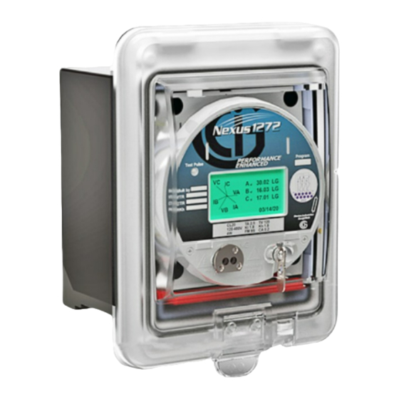
Page 45: Nexus® 1262/1272 Meter Forms
9Z and 36Z. The legacy Switchboard meter comes in an S1 form relay case, but it has an optional retrofit panel that converts the meter to fit in an M1 form panel cutout (see Chapter 12 for details on the legacy Switchboard meter). Electro Industries/GaugeTech ™ Doc# E151701 Powered by Innovation™... -
Page 46: Nexus® 1262/1272 Meter Accuracy
• Current surge withstand (at 23 C): 100 A for 10 seconds, 300 A for 3 seconds, 500 A for 1 second • The current inputs are only to be connected to external current transformers. Electro Industries/GaugeTech ™ Doc# E151701 2-10 Powered by Innovation™... - Page 47 Isolation • All inputs and outputs isolated to 2500 V • Com Ports isolated from each other to 1000 V Sensing • Accu-Measure Technology • 16-bit A/D Inputs • True RMS Electro Industries/GaugeTech ™ Doc# E151701 2-11 Powered by Innovation™...
- Page 48 • On Resistance: (23-35) • Peak Voltage: 350 V DC • Continuous Load Current: 120 mA • Peak Load Current: 350 mA (10ms) • Off-State Leakage Current @ 350 V DC: 1:A Electro Industries/GaugeTech ™ Doc# E151701 2-12 Powered by Innovation™...
- Page 49 • A hardware lock secures meter settings. • Two 10-character passwords are configurable: one password controls access to read meter digitally; a separate password controls access to meter programming. • An additional 8 level password sequence is available by user configuration. Electro Industries/GaugeTech ™ Doc# E151701 2-13 Powered by Innovation™...
- Page 50 • IEC 60687 (IEC 62053-22 and IEC 62053-23 0.2) KEMA Labs Ceritifed* • IEC 62052-11 2003 (General Requirements; Mechanical Properties; Climactic Influ- ences)* • IS IS 14697:1999, (Reaffirmed 2004)* • Measurement Canada Approved *Third party lab tested Electro Industries/GaugeTech ™ Doc# E151701 2-14 Powered by Innovation™...
-
Page 51: Nexus® 1262/1272 Meter Logging Specifications
• Freeze with Time commands enable the Nexus® meter to have internal time-driven Frozen and Frozen Event data. When the meter receives the time and interval, the data is created. For complete details, download the appropriate DNP User Manual from our website at www.electroind.com. Electro Industries/GaugeTech ™ Doc# E151701 2-15... - Page 52 2: Meter Overview This page intentionally left blank. Electro Industries/GaugeTech ™ Doc# E151701 2-16 Powered by Innovation™...
-
Page 53: 3: Operating Instructions
3: Operating Instructions 3.1: Nameplate Information... - Page 54 Model: NEXUS 1272-A-SWB2-20-60-SE-INP202 Serial#: 114-0074880532 4 Meg Memory: Class: Freq.: 60 Hz KYZ Out: Opt. Comm: Ethernet/Modem Combo Power Supply: Std. Ext 102-275V AC/DC Memory (1272): Memory (1262): Communication Options:...
- Page 55 Case Style: Power Supply: EIG Number - Model Number plus Option Numbers...
-
Page 56: Basic Operation
3.2: Basic Operation Switches and Indicators Mode Reset Test... - Page 57 Optical Port B10U Test Pulse Phase Indicator that phase has voltage but no current, and is blank if that phase has no voltage or current...
-
Page 58: Lcd Display Information
3.3: LCD Display Information Mode Details... - Page 59 Display Configurator Base Programmable Display NOTE: Low Battery Test Mode...
- Page 60 Initial Display Screens Backlight...
-
Page 61: 1: Finding Your Display's Firmware Versions
3.3.1: Finding Your Display’s Firmware Versions Profile Revenue and Energy Settings>Display Configuration... -
Page 62: Nexus 1262/1272 Programmable Display Navigation Map
3.4: Nexus 1262/1272 Programmable Display Navigation Map... -
Page 63: Using The Display Configurator
3.5: Using the Display Configurator IMPORTANT! Modus Protocol and Register Map for Nexus 1252/1262/1272 Meters ® To access the Display Configurator's programming screens Profile... - Page 64 Display Configuration...
- Page 65 Display screens available for assignment to View modes Right-click on a screen to assign it to View mode or to copy it Buttons that View Mode let you: Columns Create custom display screens, Edit display screens, or Remove display screens from the available Buttons that let you: Change the order of display screens screens list...
- Page 66 Move Up Move Down Remove Create Creating a Custom Display Screen NOTE Edit Creating a Custom Display Screen Edit Editing a Pre-defined Dis- play Screen...
- Page 67 Create New Screen Based on Selected Screen Editing a Pre-defined Display Screen Remove Create Click to create custom screen...
- Page 68 User defined You can change this number Select number of screen items OR 1 Demand,1 Timestamp The fields in These Screen Layout fields are are determined for Modbus by the number Information of items you select These fields are for multiplier setup These fields...
- Page 69 Custom Screen with 3 Item Fields The information for these fields comes Display screen from the meter’s label fields Modbus Register Item entry fields This is where you click here to can specify a enter the Modbus multiplier for your Register containing data the item...
- Page 70 Example Nexus 1252/1262/1272 Meter Modbus Manual...
- Page 71 IMPORTANT! All of the data items you select must be the same Modbus type Example: 1 Cycle Block 00090-00093 1 cycle Block Time Stamp 12/31/9999 23:59:59:99 10 msec 00094-00095 1 cycle Phase A-N Voltage +65536 V1 / D V 1/65536 V Update Nexus 1252/1262/1272 Meter Modbus Manual...
- Page 72 3.5: Type F5 Secondary 1 Cycle RMS Voltage or Current Length: 2 Registers (4 bytes) Range: +1,048,576 V 2 / 0 V 2 or +65536 I2 / 0 I2(1262 or 1272) Unit: 1/4906 V secondary or 1/65536 A2 secondary (1262 or 1272) These registers together are a four-byte unsigned integer.
- Page 73 Table 1: Entry fields Possible entries Save Upload Cancel without saving any changes...
- Page 74 NOTE: Table 2: Pre-defined LCD Screen Number Description Editing Options (Default Value) Edit Create a new screen based on selected s creen...
- Page 75 NOTES:...
- Page 76 You can change the screen number You can enter a screen label Save Upload Cancel without saving any changes...
- Page 77 Power and Energy Display Tab NOTES:...
- Page 78 Miscellaneous Tab...
- Page 79 When you have finished programming the Device Display Programmable Settings Screen Update Display Retrieve from Display Cancel Save Update Display...
-
Page 80: Using The Base Programmable Display
3.6: Using the Base Programmable Display Programming the Base Programmable Display Profile Display Configuration except for... - Page 81 NOTE:...
-
Page 82: 1: Pre-Defined Display Screens
3.6.1: Pre-Defined Display Screens Screen Number Screen Name DEL 43089263 REC 71323159 06/16/2011 3:50:44 Norm ABC ROLLING DEMAND 502.3 3:07:2003 2:07:09 06/16/2011 3:50:44 Norm ABC... - Page 83 la HARMONICS 003.67 06/18/2011 12:22:44 CDM ABC VC IC 30.02 LG 16.03 LG 17.01 LG...
-
Page 87: 4: Performing Meter Testing
édition du Manuel de relevé d'électricité. Le manuel est disponible à partir de la Edison Electric Institute, 701 Pennsylvania Avenue NW, Washington DC 20004-2696. Electro Industries/GaugeTech ™ Doc# E151701... -
Page 88: Testing Tools
The millisecond duration of each output pulse is also programmable in the meter’s Device Profile. To program the Test Pulse LED: 1. From the Device Profile menu in the CommunicatorPQA® application, click Reve- nue and Energy Settings>Internal KYZ to configure the following settings: Electro Industries/GaugeTech ™ Doc# E151701 Powered by Innovation™... -
Page 89: 2: Lcd Display
Normal Mode. The only difference is that the billing numbers stored in the meter are not updated with the real-time reading. This preserves the billing numbers while testing is performed. Electro Industries/GaugeTech ™ Doc# E151701... -
Page 90: 1: Entering Test Mode
VAh in Quadrant 1 kVAhr, Q1 VAh in Quadrant 4 VAh - Q2 and Q3 VAh in Quadrant 2 kVAhr, Q3 VAh in Quadrant 3 Watt Demand Rolling Watt Rolling Demand kWH, Del Delivered Electro Industries/GaugeTech ™ Doc# E151701 Powered by Innovation™... -
Page 91: 3: Test Mode Preset Accumulators
1. A monitor in Test Mode is out of service and is therefore not monitoring accumula- tions. The New Value field can be used to adjust for the values not monitored while in Test Mode. Electro Industries/GaugeTech ™ Doc# E151701... - Page 92 4: Performing Meter Testing 2. When replacing an old meter that has accumulations with a new meter that has no accumulations, the New Value field can be set to the value of the existing accumu- lations. Electro Industries/GaugeTech ™ Doc# E151701...
- Page 93 • A new meter has zeros for Current Values. 3. Settings can be preset for the following sets of values: • Primary Energy • Secondary Energy • Primary Energy (Quadrants) • Secondary Energy (Quadrants) • Internal Input Accumulators Electro Industries/GaugeTech ™ Doc# E151701 Powered by Innovation™...
- Page 94 Examples of some of the screens are shown below. 4. Click the Preset Boxes for the values you want to set. 5. Click Set to save your entries or Cancel to exit the screen without saving any changes. Electro Industries/GaugeTech ™ Doc# E151701...
-
Page 95: 4: Exiting Test Mode
The meter watches the Test and Reset Buttons for activity, using an extended time limit consisting of the Exit Delay time plus the programmed Block Interval Time. This insures that the meter completes a full block Demand test without interruption. After exiting Test Mode: Electro Industries/GaugeTech ™ Doc# E151701... - Page 96 Mode operation. Upon exiting Test Mode, accumulation of billing and historical log quantities does either of the following: • Resumes from the values in place when Test Mode was entered • Continues from the Test Mode Preset values (see Section 4.2.4) Electro Industries/GaugeTech ™ Doc# E151701 4-10 Powered by Innovation™...
- Page 97 This page intentionally left blank.
-
Page 99: 5: Serial Communication Wiring
Nexus® Socket meter’s Ports 1 and 4 are two-wire, RS485 connections (up to 115200 baud). Optional Communication Connections for INP200 (10/100BaseT connection) or INP202 (Combination Modem and Ethernet) are cables with appropriate connectors (see Chapter 6 and Figure 6.2). Electro Industries/GaugeTech ™ Doc# E151701... -
Page 100: Communicating To The Meter Through The Ansi Type Ii Optical
ANSI C12.13 Type II Magnetic Optical Communi- cations Coupler, such as the B10U Optical Probe, which connects to the USB port of the PC. NOTE: You can order this device from EIG’s webstore: https://www.electroind.com/product/b10u-ansi-optical-probe/ Electro Industries/GaugeTech ™ Doc# E151701 Powered by Innovation™... - Page 101 CommunicatorPQA® software. Refer to Chapter 11 in the CommunicatorPQA®, MeterManagerPQA®, and EnergyPQA.com® Software User Manual for instructions (you can download the manual from https://www.electroind.com/products/communi- catorpqa-power-monitoring-software/ - click Downloads>Tech Documents>User Man- ual). Electro Industries/GaugeTech ™ Doc# E151701 Powered by Innovation™...
-
Page 102: Rs485 Serial Communication
• Avoid both “star” and “tee” connections (see Figure 5.6). • No more than two cables should be connected at any one point on an RS485 network, whether the connections are for devices, converters or terminal strips. Electro Industries/GaugeTech ™ Doc# E151701 Powered by Innovation™... - Page 103 Slave device 1 Slave device 2 Twisted pair, shielded (SH) cable Twisted pair, shielded (SH) cable Twisted pair, shielded (SH) cable Earth Connection, preferably at single location Figure 5.5: RS485 Daisy Chain Connection Electro Industries/GaugeTech ™ Doc# E151701 Powered by Innovation™...
-
Page 104: 2: Using The Unicom 2500
Installation and Operation Manual for additional information. You can order the Unicom 2500 from EIG’s webstore: www.electroind.com/store. Select the Communi- cations Products category from the left side of the webpage. Figure 5.7 illustrates the Unicom 2500 connections for RS485. Electro Industries/GaugeTech ™ Doc# E151701... -
Page 105: 3: Rj45 Connection-Meter With Inp200 (10/100Baset) Option
Baud rate by turning the screw to point at the rate you want. 5.3.3: RJ45 Connection—Meter with INP200 (10/100BaseT) Option The INP200 Option conforms to the IEEE 802.3, 10/100BaseT specification using unshielded twisted pair (UTP) wiring. This allows you to use inexpensive RJ45 Electro Industries/GaugeTech ™ Doc# E151701... -
Page 106: 4: Modem/Ethernet Connection-Meter With Inp202 (Combo Card) Option
Set switch to FD 1, Protocol to Modbus RTU and Mode to Slave using the communication software. Insert the other end of the communication wires into the back of the first LED Display. Electro Industries/GaugeTech ™ Doc# E151701 Powered by Innovation™... - Page 107 Note on page 5-5. **Please refer to Cable Color Key, page 6-4, P40N LED Display, Back View and second bullet, page 5-5. 1262/1272 Port 4 Figure 5.8: P41N+ and Legacy P40N External Display RS485 Connection Electro Industries/GaugeTech ™ Doc# E151701 Powered by Innovation™...
-
Page 108: 6: Communication Ports On The I/O Modules
The Nexus® 1262/1272 meter’s power supply does not supply power to the I/O modules. You must use a power source, such as the EIG PSIO or PB1 (12 V). See Section 10.2.1 for PSIO details. Electro Industries/GaugeTech ™ Doc# E151701 5-10 Powered by Innovation™... - Page 109 500’), connected to the + and - lines. RT is approximately 120 Ohms. NOTES: • The meter has some level of termination internally and usually resistors are not needed. • Refer to the Cable Color Key on pages 6-5 to 6-7. Electro Industries/GaugeTech ™ Doc# E151701 5-11...
- Page 110 5: Serial Communication Wiring Male Side Port on I/O Module R T= 120 Ohms R T= 120 Ohms Meter’s Port 4 Figure 5.10: Meter and I/O Module Connections Electro Industries/GaugeTech ™ Doc# E151701 5-12 Powered by Innovation™...
-
Page 111: 8: Steps To Determine Power Needed
2. Add together the VA Ratings for the I/O modules in use to determine total power needed. 3. Each PSIO supplies 12 VA @ 12 V DC. For details on the PSIO, see sections 10.2.1 and 10.3. Electro Industries/GaugeTech ™ Doc# E151701 5-13 Powered by Innovation™... -
Page 112: 9: Remote Communication Over Telephone Linecommunicatorpqa®S Using The Rs485 Port
You must use an RS485 to RS232 converter and a Null Modem. EIG recommends using its Modem Manager. This converter has a built-in null modem and also provides line data buffering, making the telephone line communication reliable; most commer- Electro Industries/GaugeTech ™ Doc#... -
Page 113: 10: Programming Modems For Remote Communication
Modem Connected to the Nexus® Meter (the Remote Modem) • Restore modem to factory settings. This erases all previously programmed settings. • Set modem to auto answer on n rings. This sets the remote modem to answer the call after n rings. Electro Industries/GaugeTech ™ Doc# E151701 5-15 Powered by Innovation™... -
Page 114: 11: Selected Modem Strings
• Attaching the KYZ pulse outputs from other meters for pulse counting and totalizing Even though these inputs are capable of being used as high speed digital fault record- ing inputs, they serve a dual purpose as KYZ counters and totalizers. The function in Electro Industries/GaugeTech ™ Doc#... -
Page 115: 13: Irig-B Connections
Connection: Connect the (+) terminal of the Nexus® meter to the (+) terminal of the signal generating device; connect the (-) terminal of the Nexus® meter to the (-) terminal of the signal generating device. Electro Industries/GaugeTech ™ Doc# E151701 5-17 Powered by Innovation™... - Page 116 3. Connect the (+) terminal of the Nexus® meter to the (+) terminal of the signal generating device; connect the (-) terminal of the Nexus® meter to the (-) terminal of the signal generating device. Electro Industries/GaugeTech ™ Doc# E151701 5-18 Powered by Innovation™...
- Page 117 IRIG-B Port IRIG-B Time Signal Generating Device Figure 5.13: IRIG-B Communication NOTE: Please make sure that the selected clock can drive the amount of wired loads. Electro Industries/GaugeTech ™ Doc# E151701 5-19 Powered by Innovation™...
-
Page 118: 14: Time Synchronization Alternatives
You can download the manual from EIG’s website: www.electroind.com/pdf Other Time Setting Tools • Tools>Set Device Time: For manual or PC time setting • Script & Scheduler: Time stamps retrieved logs and data Electro Industries/GaugeTech ™ Doc# E151701 5-20... -
Page 119: Inp200 Onboard Ethernet
Use standard RJ45 10/100BaseT cable to connect with the Nexus® meter. The RJ45 line is inserted into the RJ45 port coming from the back of the meter with the INP200 Ethernet Option (see Figure 6.2). Electro Industries/GaugeTech ™ Doc# E151701 5-21 Powered by Innovation™... - Page 120 4. Click the Serial Port button. Make sure data matches the meter, then click Connect. Set the Network using the following steps: 1. From the Device Profile menu, click General Settings>Communications> and then click on one of the listed ports. Electro Industries/GaugeTech ™ Doc# E151701 5-22...
- Page 121 2. You will see the Device Profile Communications Settings screen. In the Network Settings section (middle of the screen), enter the following data provided by your Systems Administrator: IP Address: 10.0.0.1 (Example) Subnet Mask: 255.255.255.0 (Example) Default Gateway: 0.0.0.0 (Example) Electro Industries/GaugeTech ™ Doc# E151701 5-23 Powered by Innovation™...
- Page 122 • GE Protocol (EGD): configure GE’s EGD protocol (if the meter’s firmware supports this) • Alarm/Email: configure the alarm email notification settings • Computer Name/DNS: set a name/DNS servers • DHCP: enable DHCP functionality Electro Industries/GaugeTech ™ Doc# E151701 5-24...
- Page 123 4. Click the Connect button at the bottom of the screen. CommunicatorPQA® soft- ware connects to the meter via the Network. NOTES: • CommunicatorPQA® software always communicates via Modbus TCP for Ethernet communication, which is the default protocol for Nexus® meters. Electro Industries/GaugeTech ™ Doc# E151701 5-25...
-
Page 124: Inp202 Ethernet/Modem Combination
3. Click the Quick Connect or the Connection Manager icon in the icon tool bar. 4. Click the Serial Port button. Make sure data matches the meter, then click Connect. Set the Network using the following steps: Electro Industries/GaugeTech ™ Doc# E151701 5-26 Powered by Innovation™... - Page 125 Protocol: Modbus TCP NOTE: See Section 5.7 for the factory settings. 4. Click the Connect button at the bottom of the screen. CommunicatorPQA® soft- ware connects to the meter via the Network. Electro Industries/GaugeTech ™ Doc# E151701 5-27 Powered by Innovation™...
-
Page 126: Factory Settings
INP202 option for the first time, or at any time until the settings are changed, using the following factory settings: Device Address: 1 IP Address: 10.0.0.1 Network Port: 502 Protocol: Modbus TCP Electro Industries/GaugeTech ™ Doc# E151701 5-28 Powered by Innovation™... -
Page 127: 6: Hardware Installation
Make sure that the socket and meter current class ratings are compatible. • Make sure that all communication and auxiliary power wiring is accessible in case disconnection is required for any reason. Electro Industries/GaugeTech ™ Doc# E151701... - Page 128 • Insert the meter into the socket, making sure that the unit blades are firmly within the jaws of the socket. • Connect external devices to the appropriate communications wiring. See following Figure 6.2. RJ11 and RJ45 connectors are supplied. Electro Industries/GaugeTech ™ Doc# E151701...
- Page 129 Cable 8: Optional Aux Power Cable 1: Port 1, Port 4, IRIG-B Optional Communication Cables Cable 3: Optional Cable 2: to High-Speed Inputs KYZ Cable Figure 6.2: Socket Meter Rear View Showing Cables Electro Industries/GaugeTech ™ Doc# E151701 Powered by Innovation™...
- Page 130 6: Hardware Installation 0.87" 2.21cm 10.4" 26.42cm High High High 6.84" 17.37cm Figure 6.3: Socket Meter Mounted in A-Base Front View Electro Industries/GaugeTech ™ Doc# E151701 Powered by Innovation™...
- Page 131 6: Hardware Installation 4.57” 11.61cm 2.02” 5.13cm 6.60” 16.76cm Figure 6.4: Socket Meter in A-Base Side View Electro Industries/GaugeTech ™ Doc# E151701 Powered by Innovation™...
-
Page 132: Switchboard Meter Installation
IRIG-B Blue Purple Cable 2 High-Speed Inputs Input 8 Black Input 7 Brown Input 6 Input 5 Orange Input 4 Yellow Input 3 Green Input 2 Blue Input 1 Gray Common Purple Electro Industries/GaugeTech ™ Doc# E151701 Powered by Innovation™... - Page 133 Cable 6 RJ45 Ethernet Label Attached Blue Cable 7 Battery Label Attached Black Cable 8 Aux Power - DE Positive Neutral/Negative Black Aux Power - SE Std. Ext. Black Std. Ext. Black Electro Industries/GaugeTech ™ Doc# E151701 Powered by Innovation™...
- Page 134 6: Hardware Installation The following figures show the switchboard case meter dimensions. Figure 6.5: Switchboard Case Meter Front Dimensions (SWB3) Electro Industries/GaugeTech ™ Doc# E151701 Powered by Innovation™...
- Page 135 6: Hardware Installation Figure 6.6: Switchboard Meter Side Dimensions (SWB3) Electro Industries/GaugeTech ™ Doc# E151701 Powered by Innovation™...
- Page 136 6: Hardware Installation Figure 6.7: Switchboard Case Back Dimensions (SWB3) Electro Industries/GaugeTech ™ Doc# E151701 6-10 Powered by Innovation™...
- Page 137 If you want to remove the meter from the switchboard case before installing the case, 6.2.1: Removing the Meter from the Switchboard Case/Reinstalling the Meter into the Switchboard Case, on page 6-14, for instructions. Electro Industries/GaugeTech ™ Doc# E151701 6-11...
- Page 138 3. INSERT AND INSTALL SHARK 270 SWB3 UNIT INTO PANEL CUT OUT USING INCLUDED MOUNTING CLIPS. 4. INSERT MOUNTING CLIPS INTO SIDE SLOTS. EIG CASE REST METER ON CUTOUT WHILE MOUNTING. Figure 6.9: Switchboard Case Installation for Existing/Retrofit Installations Electro Industries/GaugeTech ™ Doc# E151701 6-12 Powered by Innovation™...
- Page 139 3. INSTALL FLAT WASHER, SPLIT WASHER, AND NUT FROM BAG. Figure 6.10: Switchboard Case Installation for New Installations NOTE: Alternatively, you can use the mounting brackets for new installations - see the instructions on the previous page. Electro Industries/GaugeTech ™ Doc# E151701 6-13 Powered by Innovation™...
-
Page 140: 1: Removing The Meter From The Switchboard Case/Reinstalling The Meter Into The Switchboard Case
1. Lift the latch and remove the front bezel. Press Lift up Latch Remove the Bezel Figure 6.11: Removing the Front Bezel 2. Pull out the paddle board. Figure 6.12: Removing the Paddle Board Electro Industries/GaugeTech ™ Doc# E151701 6-14 Powered by Innovation™... - Page 141 6: Hardware Installation 3. Move the top lever to the right (a) and move the bottom lever to the left (b). Figure 6.13: Unlocking the Cradle Electro Industries/GaugeTech ™ Doc# E151701 6-15 Powered by Innovation™...
- Page 142 6: Hardware Installation 4. Holding onto the meter, gently pull the meter cradle toward you. You can use the top lever to pull the cradle all the way out. Figure 6.14: Removing the Meter Cradle Electro Industries/GaugeTech ™ Doc# E151701 6-16 Powered by Innovation™...
- Page 143 To re-install the meter in the switchboard case: 1. Make sure the top lever is in the open position and use it to reinsert the cradle into the switchboard case. Figure 6.15: Reinserting the Meter Cradle Electro Industries/GaugeTech ™ Doc# E151701 6-17 Powered by Innovation™...
- Page 144 6: Hardware Installation 2. Lock the meter cradle into the switchboard case by moving the upper lever to the left (a), and the lower lever to the right (b). Figure 6.16: Locking the Cradle Electro Industries/GaugeTech ™ Doc# E151701 6-18...
- Page 145 Note that some effort will be needed to fully install the paddle board. Inserting the Paddle Board Paddle Board Completely Installed Figure 6.17: Reinserting the Paddle Board Electro Industries/GaugeTech ™ Doc# E151701 6-19...
- Page 146 Self-locating tabs (inside) Latch snaps into place Figure 6.18: Reinstalling the Bezel Electro Industries/GaugeTech ™ Doc# E151701 6-20 Powered by Innovation™...
-
Page 147: Internal Battery Installation And Maintenance
10 years of service during storage conditions (disconnected from terminals) or when properly installed in an energized meter. The battery should provide more than one year of service during outage Electro Industries/GaugeTech ™ Doc#... - Page 148 Otherwise proper contact will not be achieved and the meter may lose log memory and time functions. Figure 6.21: Battery Holder Detail a. Make sure the + on the battery is facing UP and toward you. Electro Industries/GaugeTech ™ Doc# E151701 6-22 Powered by Innovation™...
-
Page 149: 1: Battery Safety And Disposal
Six feet of RS485 communication/power cable harness is supplied. Allow for at least a 1.25 inch (3.17 cm) diameter hole in the mounting panel for the cable harness. See Chapter 5 for wiring details. Electro Industries/GaugeTech ™ Doc# E151701 6-23 Powered by Innovation™... - Page 150 6: Hardware Installation The display is powered by an external power source, such as the PSIO, which supplies 12 V DC. Figure 6.22: P40N+ Front and Side Dimensions Electro Industries/GaugeTech ™ Doc# E151701 6-24 Powered by Innovation™...
- Page 151 6: Hardware Installation 3.38”/8.57 cm 1.69”/ 4.29 cm 4x 0.20”/ 0.51 cm 3.38”/ 8.57 cm 04.00”/10.16 cm Figure 6.23: P40N+ ANSI Mounting Electro Industries/GaugeTech ™ Doc# E151701 6-25 Powered by Innovation™...
-
Page 152: Mounting The Nexus® External I/O Modules
#8 screw with a lock washer. 5.63”/14.30 cm 3X 1.30”/3.31 cm 1.13”/2.86 cm Mounting Bracket .090”/.23 cm Mounting Bracket 4.19”/10.64 cm Figure 6.24: I/O Modules Mounting Diagram, Overhead View Electro Industries/GaugeTech ™ Doc# E151701 6-26 Powered by Innovation™... - Page 153 PSIO Max Power: 12 VA Input Voltage: 12-60V DC 1.10”/2.54 cm 90-240V AC/DC Output Voltage: 12V DC ElectroIndustries/GaugeTech .618”/1.57 cm www.electroind.com 1.30”/3.31 cm Figure 6.26: I/O Modules Mounting Dimensions, Front View Electro Industries/GaugeTech ™ Doc# E151701 6-27 Powered by Innovation™...
- Page 154 Refer to Figure 6.28 and Section 5.3.8 for PSIO and I/O Module wiring instructions. Auxiliary Power (PSIO) is supplied through pins 3 and 4 Connection though SHIELD, + and - to meter’s Port 4 Figure 6.28: I/O Module Wiring Detail Electro Industries/GaugeTech ™ Doc# E151701 6-28 Powered by Innovation™...
-
Page 155: 7: Time Of Use Function
A season ends at midnight of the day before the start of the next season. A month ends at midnight of the month’s billing day. Electro Industries/GaugeTech ™ Doc# E151701... -
Page 156: Tou Frozen And Active Registers
Once stored, prior accumulations are always available and cannot be reset. See the CommunicatorPQA®, MeterManagerPQA®, and Ener- gyPQA.com® Software User Manual for instructions on resetting TOU accumulations. Electro Industries/GaugeTech ™ Doc# E151701... -
Page 157: Daylight Savings And Demand
Settings > Demand Integration Intervals and set the desired intervals. Click • To set Cumulative Demand Type, from the Device Profile click Revenue & Energy Settings > Cumulative Demand Type and select Block or Rolling Window. Click Electro Industries/GaugeTech ™ Doc# E151701 Powered by Innovation™... - Page 158 7: Time of Use Function This page intentionally left blank. Electro Industries/GaugeTech ™ Doc# E151701 Powered by Innovation™...
-
Page 159: 8: Transformer Loss Compensation
Ownership may change at the midway point of a transmission line where there are no substation facilities. In this case, power metering must again be compensated. This condition is shown in Figure 8.2. Electro Industries/GaugeTech ™ Doc# E151701... - Page 160 (VARs) power lost due to both iron and copper effects (reflected to the secondary of the instrument transformers). Total Secondary Watt Loss = Vmeasured Imeasured ----------------------------- --------------------------- - %LFWE %LWCU TotalTransformerLoss TransformerFullScale Vnominal Inominal Electro Industries/GaugeTech ™ Doc# E151701 Powered by Innovation™...
- Page 161 • Calculates numerically, eliminating the environmental effects that cause inaccura- cies in electromechanical compensators. • Performs bidirectional loss compensation. • Requires no additional wiring; the compensation occurs internally. • Imposes no additional electrical burden when performing loss compensation. Electro Industries/GaugeTech ™ Doc# E151701 Powered by Innovation™...
-
Page 162: Nexus® 1262/1272 Meter's Transformer Loss Compensation
Voltage and current and taking into account the number of elements used in the metering installation. For three-element meters, the installation must be normalized to the phase-to-neutral Voltage and the phase current; in two-element meters the Electro Industries/GaugeTech ™ Doc# E151701 Powered by Innovation™... -
Page 163: 1: Loss Compensation In Three Element Installations
Correct calculation of loss compensation also requires knowledge of the meter installation. In order to calculate the loss compensation settings you will need the following information regarding the meter and the installation: • Number of meter elements • Potential transformer ratio (PTR) Electro Industries/GaugeTech ™ Doc# E151701 Powered by Innovation™... -
Page 164: 1: Three-Element Loss Compensation Worksheet
Date Trf. Bank Trf Manf Trf Serial Calculation Transformer Data (from Transformer Manufacturer's Test Sheet) Table 2: Winding Voltage Connection HV - High ∆ XV - Low ∆ YV - Tertiary ∆ Electro Industries/GaugeTech ™ Doc# E151701 Powered by Innovation™... - Page 165 Test Voltage is generally Phase-to-Phase for three-phase transformers. Calculate Phase-to-Neutral Voltage by dividing Phase-to-Phase Voltage by the square root of 3. Calculate Full Load Current by dividing the (1-Phase kW Self-Cooled Rating) by the (Phase-to-Neutral Voltage) and multiplying by 1000. Electro Industries/GaugeTech ™ Doc# E151701...
- Page 166 Secondary of the Power Transformer. These numbers are obtained by dividing the Transformer Voltage and Current by their respective Multipliers. The Meter/Trf values for Voltage and Current are obtained by dividing the Meter Base values by the TrfIT Secondary values. Electro Industries/GaugeTech ™ Doc# E151701...
- Page 167 100 = (______________) * (________________) / 100 = _______________ kVA Full-Load Loss VAR (kVAR) = SQRT((Full-Load Loss kVA)2 - (Full-Load Loss kW)2) = SQRT((_________________)2 - (________________)2) = SQRT((__________________) - (_________________)) = SQRT (_________________) = _________________ Electro Industries/GaugeTech ™ Doc# E151701 Powered by Innovation™...
- Page 168 (Value at Trf Base). Loss Watts Percentage Values Meter Base kVA = 600 * (PT Multiplier) * (CT Multiplier) / 1000 = 600 * (____________) * (___________) / 1000 = ________________ Electro Industries/GaugeTech ™ Doc# E151701 8-10 Powered by Innovation™...
- Page 169 Meter Base) by (Meter Base kVA) and multiplying by 100. Enter calculated % Loss Watts values into the Nexus® meter using Communica- torPQA® software. Refer to Appendix B of the CommunicatorPQA®, MeterManager- PQA®, and EnergyPQA.com® Software User Manual for instructions. Electro Industries/GaugeTech ™ Doc# E151701 8-11 Powered by Innovation™...
- Page 170 8: Transformer Loss Compensation This page intentionally left blank. Electro Industries/GaugeTech ™ Doc# E151701 8-12 Powered by Innovation™...
-
Page 171: 9: External I/O Modules
Comes with 2 DIN rail mounting clips. Mounting Brackets (MBIO) Female RS485 Side Port LEDs I/O Port (Size and Pin Male RS485 Configuration Vary) Side Port Reset Button Figure 9.1: I/O Module Components Electro Industries/GaugeTech ™ Doc# E151701 Powered by Innovation™... - Page 172 Four KYZ Pulse Outputs 0-5Vdc, 0-10Vdc) or Eight Status Inputs 0-1mA Analog Input Module INPUT 1 INPUT 2 INPUT 3 INPUT 4 INPUT 5 INPUT 6 INPUT 7 INPUT 8 RESET RESET Electro Industries/GaugeTech ™ Doc# E151701 Powered by Innovation™...
-
Page 173: I/O Module Installation
Max Power: 12 VA INPUT 4 Max Power: 12 VA Input Voltage: 90-240V AC/DC Output Voltage: 12V DC Input Voltage: 90-240V AC/DC Electro Industries/Gaugetech Output Voltage: 12V DC www.electroind.com RESET Electro Industries/Gaugetech www.electroind.com Figure 9.3: Power Flow from PSIO to I/O Module Electro Industries/GaugeTech ™... -
Page 174: Using The Psio With Multiple I/O Modules
I/O Port (Size and pin configuration vary) Figure 9.5: PSIO Used with Multiple I/O Modules NOTE: As shown, the PSIO must be to the right of I/O Modules when viewing the side label. Electro Industries/GaugeTech ™ Doc# E151701 Powered by Innovation™... -
Page 175: 1: Steps For Attaching Multiple I/O Modules
This final tightening will lock the whole group together as a unit. 9. Attach the right Mounting Bracket to the right side of the group using the small Phillips head screws provided. Electro Industries/GaugeTech ™ Doc# E151701... - Page 176 Note that the clip should be positioned as shown above, with the indented side facing the back. b. Repeat step a for the second bracket. Electro Industries/GaugeTech ™ Doc# E151701...
-
Page 177: Factory Settings And Reset Button
RESET button for 3 seconds; the module will reset to a default address of 247 at 57600 baud rate for 30-seconds. This enables you to interrogate the I/O using the CommunicatorPQA® software; see the Modbus Communicating I/O Modules User Manual. Electro Industries/GaugeTech ™ Doc# E151701... -
Page 178: Analog Transducer Signal Output Modules
All outputs share a single common point. This is also an isolated connection (from ground). The Modbus Map for the Analog Output Module (and operating details) can be found in the Modbus Communicating I/O Modules Manual. Electro Industries/GaugeTech ™ Doc# E151701... -
Page 179: 2: Normal Mode
The device will operate with the following default parameters: Address: 247 (F7H) Baud Rate: 57600 Baud Transmit Delay Time: 20 ms Normal Operation is prevented by a number of occurrences. See Section 9.4 for details. Electro Industries/GaugeTech ™ Doc# E151701 Powered by Innovation™... -
Page 180: Analog Input Modules
All inputs share a single common point. This is also an isolated connection (from ground). The Modbus Map for the Analog Output Module (and operating details) can be found in the Modbus Communicating I/O Modules Manual. Electro Industries/GaugeTech ™ Doc# E151701 9-10 Powered by Innovation™... -
Page 181: 2: Normal Mode
The device will operate with the following default parameters: Address: 247 (F7H) Baud Rate: 57600 Baud Transmit Delay Time: 20 ms Normal Operation is prevented by a number of occurrences. See Section 9.4 for details. Electro Industries/GaugeTech ™ Doc# E151701 9-11 Powered by Innovation™... -
Page 182: Digital Dry Contact Relay Output (Form C) Module
CommunicatorPQA® software. See the Commu- nicatorPQA®, MeterManagerPQA®, and EnergyPQA.com® Software User Manual for details on programming limits. The Modbus Map for the Analog Output Module (and operating details) can be found in the Modbus Communicating I/O Modules Manual. Electro Industries/GaugeTech ™ Doc# E151701 9-12... -
Page 183: 2: Communication
Some situations will cause the device to operate with the above Default Parameters. See Section 9.4 for details of Default Mode. 9.7.3: Normal Mode Normal Mode consists of one process: the device accepts new commands to control the relays. Electro Industries/GaugeTech ™ Doc# E151701 9-13... -
Page 184: Digital Solid State Pulse Output (Kyz) Module
The Modbus Map for the KYZ Pulse Output Module (and operating details) can be found in the Modbus Communicating I/O Modules Manual. NC = Normally Closed; NO = Normally Open; C = Common. Electro Industries/GaugeTech ™ Doc# E151701 9-14 Powered by Innovation™... -
Page 185: 2: Communication
Energy/Pulse Value and the Pending Pulses Value for that channel has not reached the maximum limit, then Residual is decremented appropriately and the Pending Pulses is increased by two, signifying two more transitions and one more pulse. Electro Industries/GaugeTech ™ Doc# E151701 9-15 Powered by Innovation™... - Page 186 Bit 5:1 = 1 or more Programmable Settings are invalid Bit 6:1 = 1 or more Programmable Settings have been modified Bit 7:1 = Forced Default by Reset Value Bit 15:1 = Normal Operation of the device is disabled Electro Industries/GaugeTech ™ Doc# E151701 9-16 Powered by Innovation™...
-
Page 187: Digital Status Input Module
Baud Rate: 57600 Transmit Delay Time: 20ms 9.9.1: Overview The Digital Status Input Module is used either for additional status detect or for accu- mulating pulses from external equipment, such as power meters, water meters, etc. Electro Industries/GaugeTech ™ Doc# E151701 9-17... -
Page 188: 2: Communication
The inputs are represented by Channel 1 in the LSB through Channel 8 in the MSB of the low order byte of the register. The Modbus Map for the Digital Status Input Modules (and operating details) can be found in the Modbus Communicating I/O Modules Manual. Electro Industries/GaugeTech ™ Doc# E151701 9-18 Powered by Innovation™... -
Page 189: 10: Electrical Installation
Do not apply more than the maximum voltage the meter or any attached device can withstand. Refer to meter and/or device labels and to the Specifications for all devices before applying voltages. Do not HIPOT/Dielectric test any Outputs, Inputs or Com- munications terminals. Electro Industries/GaugeTech ™ Doc# E151701 10-1 Powered by Innovation™... - Page 190 EQUIPMENT AND WITHIN EASY REACH OF THE OPERATOR. THE SWITCH SHALL BE MARKED AS THE DISCONNECTING DEVICE FOR THE EQUIPMENT. L’installation des compteurs de Nexus 1262/1272 doit être effectuée seulement par un personnel qualifié qui suit les normes relatives aux précautions de sécurité...
- Page 191 EIG nécessite l'utilisation de les fusibles pour les fils de tension et alimentations élec- triques, ainsi que des coupe-circuits pour prévenir les tensions dangereuses ou endommagements de transformateur de courant si l'unité Nexus 1262/1272 doit être enlevée du service (voir 10.1.1: Voltage Fuses, page 10-4, pour les spécifications des fusibles).
-
Page 192: 1: Voltage Fuses
• Use a 3 A fuse on each voltage input. EIG offers the EI-CP Panel meter protective fuse kit, which can be ordered from EIG’s webstore: www.electroind.com/store. Select Fuse Kits from the list on the left side of the webpage. Electro Industries/GaugeTech ™ Doc# E151701 10-4 Powered by Innovation™... -
Page 193: Blade Configuration For Forms 9S, 36S, And 45S
NOTE: The forms referred to in this chapter comply with ANSI forms 9S, 36S and 45S. Figure 10.1: Form 9S & 36S Base with Knock Out Holes Figure 10.2: Form 45S Base with Knock Out Holes Electro Industries/GaugeTech ™ Doc# E151701 10-5 Powered by Innovation™... -
Page 194: Socket Meter Wiring Diagrams
• Les connexions de garde pour les transformateurs sont omises dans les schémas et ne sont pas nécessaires afin que le compteur fonctionne correctement. Toutefois, nous vous recommandons fortement ces connexions pour réduire les risques de choc. Electro Industries/GaugeTech ™ Doc# E151701 10-6 Powered by Innovation™... - Page 195 également pas représentés. Pour éviter les chocs élec- triques, nous vous recommandons d'utiliser ces commutateurs de court-circuit (blocs). Assurez-vous que les côtés secondaires des transformateurs de courant sont court-circuités avant de les déconnecter des bornes d'entrée de courant du compteur. Electro Industries/GaugeTech ™ Doc# E151701 10-7...
- Page 196 Shorting switches (blocks) for the current transformers’ secondary side are also not shown. To prevent electrical shock we recommended you use such shorting switches (blocks). Make sure the CTs’ second- ary are shorted before disconnecting them from the meter’s current input terminals. Electro Industries/GaugeTech ™ Doc#...
- Page 197 Shorting switches (blocks) for the current transformers’ secondary side are also not shown. To prevent electrical shock we recommended you use such shorting switches (blocks). Make sure the CTs’ second- ary are shorted before disconnecting them from the meter’s current input terminals. Electro Industries/GaugeTech ™ Doc#...
- Page 198 Shorting switches (blocks) for the current transformers’ secondary side are also not shown. To prevent electrical shock we recommended you use such shorting switches (blocks). Make sure the CTs’ second- ary are shorted before disconnecting them from the meter’s current input terminals. Electro Industries/GaugeTech ™ Doc#...
- Page 199 Shorting switches (blocks) for the current transformers’ secondary side are also not shown. To prevent electrical shock we recommended you use such shorting switches (blocks). Make sure the CTs’ second- ary are shorted before disconnecting them from the meter’s current input terminals. Electro Industries/GaugeTech ™ Doc#...
- Page 200 Shorting switches (blocks) for the current transformers’ secondary side are also not shown. To prevent electrical shock we recommended you use such shorting switches (blocks). Make sure the CTs’ second- ary are shorted before disconnecting them from the meter’s current input terminals. Electro Industries/GaugeTech ™ Doc#...
- Page 201 Shorting switches (blocks) for the current transformers’ secondary side are also not shown. To prevent electrical shock we recommended you use such shorting switches (blocks). Make sure the CTs’ second- ary are shorted before disconnecting them from the meter’s current input terminals. Electro Industries/GaugeTech ™ Doc#...
- Page 202 Shorting switches (blocks) for the current transformers’ secondary side are also not shown. To prevent electrical shock we recommended you use such shorting switches (blocks). Make sure the CTs’ second- ary are shorted before disconnecting them from the meter’s current input terminals. Electro Industries/GaugeTech ™ Doc#...
- Page 203 Shorting switches (blocks) for the current transformers’ secondary side are also not shown. To prevent electrical shock we recommended you use such shorting switches (blocks). Make sure the CTs’ second- ary are shorted before disconnecting them from the meter’s current input terminals. Electro Industries/GaugeTech ™ Doc#...
- Page 204 Shorting switches (blocks) for the current transformers’ secondary side are also not shown. To prevent electrical shock we recommended you use such shorting switches (blocks). Make sure the CTs’ second- ary are shorted before disconnecting them from the meter’s current input terminals. Electro Industries/GaugeTech ™ Doc#...
- Page 205 Shorting switches (blocks) for the current transformers’ secondary side are also not shown. To prevent electrical shock we recommended you use such shorting switches (blocks). Make sure the CTs’ second- ary are shorted before disconnecting them from the meter’s current input terminals. Electro Industries/GaugeTech ™ Doc#...
- Page 206 Shorting switches (blocks) for the current transformers’ secondary side are also not shown. To prevent electrical shock we recommended you use such shorting switches (blocks). Make sure the CTs’ second- ary are shorted before disconnecting them from the meter’s current input terminals. Electro Industries/GaugeTech ™ Doc#...
- Page 207 Shorting switches (blocks) for the current transformers’ secondary side are also not shown. To prevent electrical shock we recommended you use such shorting switches (blocks). Make sure the CTs’ second- ary are shorted before disconnecting them from the meter’s current input terminals. Electro Industries/GaugeTech ™ Doc#...
- Page 208 Shorting switches (blocks) for the current transformers’ secondary side are also not shown. To prevent electrical shock we recommended you use such shorting switches (blocks). Make sure the CTs’ second- ary are shorted before disconnecting them from the meter’s current input terminals. Electro Industries/GaugeTech ™ Doc#...
- Page 209 Shorting switches (blocks) for the current transformers’ secondary side are also not shown. To prevent electrical shock we recommended you use such shorting switches (blocks). Make sure the CTs’ second- ary are shorted before disconnecting them from the meter’s current input terminals. Electro Industries/GaugeTech ™ Doc#...
- Page 210 Shorting switches (blocks) for the current transformers’ secondary side are also not shown. To prevent electrical shock we recommended you use such shorting switches (blocks). Make sure the CTs’ second- ary are shorted before disconnecting them from the meter’s current input terminals. Electro Industries/GaugeTech ™ Doc#...
- Page 211 Shorting switches (blocks) for the current transformers’ secondary side are also not shown. To prevent electrical shock we recommended you use such shorting switches (blocks). Make sure the CTs’ second- ary are shorted before disconnecting them from the meter’s current input terminals. Electro Industries/GaugeTech ™ Doc#...
-
Page 212: 9S Meter Mounted In S/A Adapter
The socket meter is “pushed” into the S/A Adapter until the meter “snaps” into place. The blades on the back of the socket meter make the proper connection. See Figures 10.1 to 10.8 for the 9S wiring diagrams. Figure 10.19: Form 9S mounted in an S/A Adapter (front removed) Electro Industries/GaugeTech ™ Doc# E151701 10-24 Powered by Innovation™... -
Page 213: Swb3 Switchboard Meter Wiring Diagrams
à Section 10.1. REMARQUE pour Tous les schémas de câblage: • Les connexions de garde pour les transformateurs sont omises dans les schémas et ne sont pas nécessaires afin que le compteur fonctionne correctement. Toutefois, Electro Industries/GaugeTech ™ Doc# E151701 10-25 Powered by Innovation™... - Page 214 également pas représentés. Pour éviter les chocs élec- triques, nous vous recommandons d'utiliser ces commutateurs de court-circuit (blocs). Assurez-vous que les côtés secondaires des transformateurs de courant sont court-circuités avant de les déconnecter des bornes d'entrée de courant du compteur. Electro Industries/GaugeTech ™ Doc# E151701 10-26...
- Page 215 Shorting switches (blocks) for the current transformers’ secondary side are also not shown. To prevent electrical shock we recommended you use such shorting switches (blocks). Make sure the CTs’ second- ary are shorted before disconnecting them from the meter’s current input terminals. Electro Industries/GaugeTech ™ Doc#...
- Page 216 Shorting switches (blocks) for the current transformers’ secondary side are also not shown. To prevent electrical shock we recommended you use such shorting switches (blocks). Make sure the CTs’ second- ary are shorted before disconnecting them from the meter’s current input terminals. Electro Industries/GaugeTech ™ Doc#...
- Page 217 Shorting switches (blocks) for the current transformers’ secondary side are also not shown. To prevent electrical shock we recommended you use such shorting switches (blocks). Make sure the CTs’ second- ary are shorted before disconnecting them from the meter’s current input terminals. Electro Industries/GaugeTech ™ Doc#...
- Page 218 Shorting switches (blocks) for the current transformers’ secondary side are also not shown. To prevent electrical shock we recommended you use such shorting switches (blocks). Make sure the CTs’ second- ary are shorted before disconnecting them from the meter’s current input terminals. Electro Industries/GaugeTech ™ Doc#...
- Page 219 Shorting switches (blocks) for the current transformers’ secondary side are also not shown. To prevent electrical shock we recommended you use such shorting switches (blocks). Make sure the CTs’ second- ary are shorted before disconnecting them from the meter’s current input terminals. Electro Industries/GaugeTech ™ Doc#...
- Page 220 Shorting switches (blocks) for the current transformers’ secondary side are also not shown. To prevent electrical shock we recommended you use such shorting switches (blocks). Make sure the CTs’ second- ary are shorted before disconnecting them from the meter’s current input terminals. Electro Industries/GaugeTech ™ Doc#...
- Page 221 Shorting switches (blocks) for the current transformers’ secondary side are also not shown. To prevent electrical shock we recommended you use such shorting switches (blocks). Make sure the CTs’ second- ary are shorted before disconnecting them from the meter’s current input terminals. Electro Industries/GaugeTech ™ Doc#...
- Page 222 Shorting switches (blocks) for the current transformers’ secondary side are also not shown. To prevent electrical shock we recommended you use such shorting switches (blocks). Make sure the CTs’ second- ary are shorted before disconnecting them from the meter’s current input terminals. Electro Industries/GaugeTech ™ Doc#...
- Page 223 Shorting switches (blocks) for the current transformers’ secondary side are also not shown. To prevent electrical shock we recommended you use such shorting switches (blocks). Make sure the CTs’ second- ary are shorted before disconnecting them from the meter’s current input terminals. Electro Industries/GaugeTech ™ Doc#...
- Page 224 Shorting switches (blocks) for the current transformers’ secondary side are also not shown. To prevent electrical shock we recommended you use such shorting switches (blocks). Make sure the CTs’ second- ary are shorted before disconnecting them from the meter’s current input terminals. Electro Industries/GaugeTech ™ Doc#...
- Page 225 Shorting switches (blocks) for the current transformers’ secondary side are also not shown. To prevent electrical shock we recommended you use such shorting switches (blocks). Make sure the CTs’ second- ary are shorted before disconnecting them from the meter’s current input terminals. Electro Industries/GaugeTech ™ Doc#...
- Page 226 Shorting switches (blocks) for the current transformers’ secondary side are also not shown. To prevent electrical shock we recommended you use such shorting switches (blocks). Make sure the CTs’ second- ary are shorted before disconnecting them from the meter’s current input terminals. Electro Industries/GaugeTech ™ Doc#...
-
Page 227: 11: Legacy Switchboard Meter (Non-Swb3)
The Switchboard meter comes in an S1 form relay case, but it has an optional retrofit panel that converts the meter to fit in an M1 form panel cutout. See Section 11.6 for details. The Switchboard meter operates in the same way as the Socket meter. Electro Industries/GaugeTech ™ Doc# E151701 11-1 Powered by Innovation™... -
Page 228: Labels
9Z and 36Z and there may be some additional items, depending upon the options selected. See Chapter 3 for a description of the components on the front and shroud labels. Figure 11.2: Switchboard Meter, Front View Electro Industries/GaugeTech ™ Doc# E151701 11-2 Powered by Innovation™... -
Page 229: Specifications And Dimensions
L N PE Power In Network Phone Line Ia - Hi Ib - Hi Ic - Hi 0.50" (1.27 cm) 5.60" (14.22 cm) 6.58" (16.71 cm) Figure 11.4: Switchboard Meter Dimensions, Back Electro Industries/GaugeTech ™ Doc# E151701 11-3 Powered by Innovation™... - Page 230 11: Switchboard Meter 6.25" (15.88 cm) 2.0" 7.0" (17.78 cm) 5.08 cm 9.0" (22.86 cm) Figure 11.5: Switchboard Meter Dimensions, Side Electro Industries/GaugeTech ™ Doc# E151701 11-4 Powered by Innovation™...
- Page 231 IMPORTANT! Check drill holes for the mounting screw you are using, to insure that the mounting screw fits the box tightly enough to hold the box in place. You can use a washer for a slightly smaller mounting screw. Electro Industries/GaugeTech ™ Doc#...
-
Page 232: Installation
• IRIG-B • Modem Gateway RS485 3. Position the Switchboard case front against the four screw holes and secure it by turning the four built-in screws in each of the corners. See Figure 11.7. Electro Industries/GaugeTech ™ Doc# E151701 11-6... - Page 233 11: Switchboard Meter Built-in Screws Figure 11.7: Switchboard Case Front Showing 4 Screw Holes Figure 11.8: Switchboard Meter Back Showing Connectors Electro Industries/GaugeTech ™ Doc# E151701 11-7 Powered by Innovation™...
-
Page 234: Wiring Diagrams
ATTENTION! Tout travail de câblage doit être effectué par un professionnel agréé. Les procédures, matériaux, équipements et connexions d'installation actuels doivent être conformes aux codes et aux normes applicables. Pour voir d'importantes exi- gences de sécurité, vous référer à Section 11.1. Electro Industries/GaugeTech ™ Doc# E151701 11-8 Powered by Innovation™... - Page 235 également pas représentés. Pour éviter les chocs élec- triques, nous vous recommandons d'utiliser ces commutateurs de court-circuit (blocs). Assurez-vous que les côtés secondaires des transformateurs de courant sont court-circuités avant de les déconnecter des bornes d'entrée de courant du compteur. Electro Industries/GaugeTech ™ Doc# E151701 11-9...
- Page 236 Shorting switches (blocks) for the current transformers’ secondary side are also not shown. To prevent electrical shock we recommended you use such shorting switches (blocks). Make sure the CTs’ second- ary are shorted before disconnecting them from the meter’s current input terminals. Electro Industries/GaugeTech ™ Doc#...
- Page 237 Shorting switches (blocks) for the current transformers’ secondary side are also not shown. To prevent electrical shock we recommended you use such shorting switches (blocks). Make sure the CTs’ second- ary are shorted before disconnecting them from the meter’s current input terminals. Electro Industries/GaugeTech ™ Doc#...
- Page 238 Shorting switches (blocks) for the current transformers’ secondary side are also not shown. To prevent electrical shock we recommended you use such shorting switches (blocks). Make sure the CTs’ second- ary are shorted before disconnecting them from the meter’s current input terminals. Electro Industries/GaugeTech ™ Doc#...
- Page 239 Shorting switches (blocks) for the current transformers’ secondary side are also not shown. To prevent electrical shock we recommended you use such shorting switches (blocks). Make sure the CTs’ second- ary are shorted before disconnecting them from the meter’s current input terminals. Electro Industries/GaugeTech ™ Doc#...
- Page 240 Shorting switches (blocks) for the current transformers’ secondary side are also not shown. To prevent electrical shock we recommended you use such shorting switches (blocks). Make sure the CTs’ second- ary are shorted before disconnecting them from the meter’s current input terminals. Electro Industries/GaugeTech ™ Doc#...
- Page 241 Shorting switches (blocks) for the current transformers’ secondary side are also not shown. To prevent electrical shock we recommended you use such shorting switches (blocks). Make sure the CTs’ second- ary are shorted before disconnecting them from the meter’s current input terminals. Electro Industries/GaugeTech ™ Doc#...
- Page 242 Shorting switches (blocks) for the current transformers’ secondary side are also not shown. To prevent electrical shock we recommended you use such shorting switches (blocks). Make sure the CTs’ second- ary are shorted before disconnecting them from the meter’s current input terminals. Electro Industries/GaugeTech ™ Doc#...
- Page 243 Shorting switches (blocks) for the current transformers’ secondary side are also not shown. To prevent electrical shock we recommended you use such shorting switches (blocks). Make sure the CTs’ second- ary are shorted before disconnecting them from the meter’s current input terminals. Electro Industries/GaugeTech ™ Doc#...
- Page 244 Shorting switches (blocks) for the current transformers’ secondary side are also not shown. To prevent electrical shock we recommended you use such shorting switches (blocks). Make sure the CTs’ second- ary are shorted before disconnecting them from the meter’s current input terminals. Electro Industries/GaugeTech ™ Doc#...
- Page 245 Shorting switches (blocks) for the current transformers’ secondary side are also not shown. To prevent electrical shock we recommended you use such shorting switches (blocks). Make sure the CTs’ second- ary are shorted before disconnecting them from the meter’s current input terminals. Electro Industries/GaugeTech ™ Doc#...
- Page 246 Shorting switches (blocks) for the current transformers’ secondary side are also not shown. To prevent electrical shock we recommended you use such shorting switches (blocks). Make sure the CTs’ second- ary are shorted before disconnecting them from the meter’s current input terminals. Electro Industries/GaugeTech ™ Doc#...
- Page 247 Shorting switches (blocks) for the current transformers’ secondary side are also not shown. To prevent electrical shock we recommended you use such shorting switches (blocks). Make sure the CTs’ second- ary are shorted before disconnecting them from the meter’s current input terminals. Electro Industries/GaugeTech ™ Doc#...
-
Page 248: E137370 Retrofit Panel - S1 To M1 Case Retrofit
2. Place the switchboard meter with retrofit panel into the space for the M1 case and attach the retrofit panel using screws in all four corner holes. 1262/1272 Switchboard Meter Retrofit Panel Panel with M1 Cutout Figure 11.21: Attaching the Panel and Inserting the Meter Electro Industries/GaugeTech ™ Doc# E151701 11-22 Powered by Innovation™... - Page 249 4X Ø.250 3.767 2.296 4X Ø .250 82° x Ø .375 5.750 +.010 -.001 .750 8.625 4.375 15.750 16.50 .0935 Side Dimensions Front Dimensions (in inches) 11. 22: E137370 Retrofit Panel Dimensions Electro Industries/GaugeTech ™ Doc# E151701 11-23 Powered by Innovation™...
- Page 250 11: Switchboard Meter This page intentionally left blank. Electro Industries/GaugeTech ™ Doc# E151701 11-24 Powered by Innovation™...
-
Page 251: 12: Meter Calculations
Root Mean Square (RMS) of Line Currents: N = number of samples For Wye: x = a, b, c, n For Delta: x = a, b, c Electro Industries/GaugeTech ™ Doc# E151701 12-1 Powered by Innovation™... - Page 252 Power (Watts) per phase: N = number of samples For Wye: x = a, b, c Apparent Power (VA) per phase: For Wye: x = a, b, c Electro Industries/GaugeTech ™ Doc# E151701 12-2 Powered by Innovation™...
- Page 253 For Delta: ab t bc t Reactive Power (VAR) Total: N = number of samples For Wye: Electro Industries/GaugeTech ™ Doc# E151701 12-3 Powered by Innovation™...
- Page 254 ⎥ ⎢ ⎥ ⎣ ⎦ ⎣ ⎦ Apparent Power (VA) Total: For Wye: For Delta: Total Q: For Wye: For Delta: Electro Industries/GaugeTech ™ Doc# E151701 12-4 Powered by Innovation™...
- Page 255 Total Average Power Factor: x = Quadrants 1 & 4 (positive Wh), Quadrants 2 & 3 (negative Wh) T Avg Phase Angles: x = a, b, c Electro Industries/GaugeTech ™ Doc# E151701 12-5 Powered by Innovation™...
- Page 256 RMS KFactor Voltage Imbalance: N = number of samples Current Imbalance: CalcN Electro Industries/GaugeTech ™ Doc# E151701 12-6 Powered by Innovation™...
-
Page 257: Demand Integrators
Further, every 5 minutes, the subinterval averages are averaged in groups of 3 (12:00. 12:05, 12:10, 12:15. etc.) to produce a fifteen (5x3) minute average every 5 minutes (rolling (sliding) every 5 minutes) (11:55-12:10, 12:00-12:15, etc.). Electro Industries/GaugeTech ™ Doc#... - Page 258 As we progress into the subinterval, (for example, up to 12:11), the Predictive Window Demand will be the average of the first two subintervals (12:00- 12:05, 12:05-12:10), the actual values of the current subinterval (12:10-12:11) and Electro Industries/GaugeTech ™ Doc#...
- Page 259 Partial Electro Industries/GaugeTech ™ Doc# E151701 12-9 Powered by Innovation™...
- Page 260 Electro Industries/GaugeTech ™ Doc# E151701 12-10 Powered by Innovation™...
-
Page 261: 13: En 50160/Iec 61000-4-15 Flicker
35 Hz. The second filter is a weighting filter that simulates the response of the human visual system to sinusoidal Voltage fluctuations of a coiled filament, gas-filled lamp (60 W - 230 V). The filter implementation of this function is as specified in IEC 61000-4-15. Electro Industries/GaugeTech ™ Doc# E151701 13-1 Powered by Innovation™... - Page 262 P(1s) = (P(.7) + P(1) + P(1.5))/3 P(3s) = (P(2.2) + P(3) + P(4))/3 P(10s) = (P(6) + P(8) + P(10) + P(13) + P(17))/5 P(50s) = (P(30) + P(50) + P(80))/3 Electro Industries/GaugeTech ™ Doc# E151701 13-2...
-
Page 263: 1: Summary
Plt = Value based on 12 Pst values. Measurement Procedure: 1. Original Signal with amplitude variations. 2. Square demodulator. 3. Weighted filter. 4. Low pass filter 1st order. 5. Statistical computing. Electro Industries/GaugeTech ™ Doc# E151701 13-3 Powered by Innovation™... -
Page 264: Flicker Setup
You must set up several parameters to properly configure Flicker. 1. Select the Profile icon from CommunicatorPQA® software's Icon bar. 2. From the Device Profile screen, double-click Power Quality and Alarm Settings>EN 50160/IEC 61000-4-30 Flicker. You will see the screen shown below. Electro Industries/GaugeTech ™ Doc# E151701 13-4... -
Page 265: Flicker Polling Screen
1. From the CommunicatorPQA® Title bar, select Real-Time Poll>Power Quality and Alarms>Flicker. You will see the screen shown below. Main screen: This section describes the Main Screen functions. These functions are found on the left side of the screen. Electro Industries/GaugeTech ™ Doc# E151701 13-5... - Page 266 Stop Time is recorded and the current Max/Min values are cleared. • Clicking on Start starts Flicker processing. Start Time is recorded. • Clicking on Reset causes the Max/Min values to be cleared and restarts the Flicker Pst and Plt timers. Electro Industries/GaugeTech ™ Doc# E151701 13-6 Powered by Innovation™...
- Page 267 • Current Pst values for Va, Vb and Vc and the time of computation. • Current Pst Max values for Va, Vb and Vc since the last reset and the time of the last reset. Electro Industries/GaugeTech ™ Doc# E151701 13-7 Powered by Innovation™...
- Page 268 • Current Plt Min values for Va, Vb and Vc since the last reset and the time of the last reset. 2. Click OK to exit the EN 50160/IEC 61000-4-30 Flicker Polling screen; click Print to print all of the Readings views. Electro Industries/GaugeTech ™ Doc# E151701 13-8 Powered by Innovation™...
-
Page 269: Logging
• Displayed values include Pst and Plt Max and Min for Va, Vb and Vc. NOTE: Max and Min values are only displayed; they cannot be graphed. However, Max and Min values are available for export. Electro Industries/GaugeTech ™ Doc#... -
Page 270: Performance Notes
Operation is at 230 V for 50 Hz and 120 V for 60 Hz as per specification. If the input Voltage is different, the system will normalize it to 230 V or 120 V for computational purposes. Electro Industries/GaugeTech ™ Doc#... -
Page 271: A: Transformer Loss Compensation Spreadsheet And Examples
IMPORTANT! Refer to Appendix B of the CommunicatorPQA®, MeterManagerPQA®, and EnergyPQA.com® Software User Manual for additional instructions and informa- tion on the Transformer Line Loss application. Electro Industries/GaugeTech ™ Doc# E151701 Powered by Innovation™... - Page 272 A: TLC Spreadsheet and Examples Electro Industries/GaugeTech ™ Doc# E151701 Powered by Innovation™...
- Page 273 A: TLC Spreadsheet and Examples Electro Industries/GaugeTech ™ Doc# E151701 Powered by Innovation™...
- Page 274 A: TLC Spreadsheet and Examples Electro Industries/GaugeTech ™ Doc# E151701 Powered by Innovation™...
- Page 275 A: TLC Spreadsheet and Examples Electro Industries/GaugeTech ™ Doc# E151701 Powered by Innovation™...
- Page 276 A: TLC Spreadsheet and Examples This page intentionally left blank. Electro Industries/GaugeTech ™ Doc# E151701 Powered by Innovation™...
-
Page 277: Glossary
A after two time intervals and 99.9 A after three time intervals. Average (Input Pulse When applied to Input Pulse Accumulations, the Accumulations: “Average” refers to the block (fixed) window average value of the input pulses. Electro Industries/GaugeTech ™ Doc# E154701 GL-1 Powered by Innovation™... - Page 278 15 minutes. This calculated average corresponds to the demand calculations performed by most electric utilities in monitoring user power demand. (See Rolling Window Average.) Electro Industries/GaugeTech ™ Doc# E154701 GL-2 Powered by Innovation™...
- Page 279 Slave ignores the request. CT (Current) Ratio: A Current Transformer Ratio is used to scale the value of the current from a secondary value up to the primary side of an instrument transformer. Electro Industries/GaugeTech ™ Doc# E154701 GL-3...
- Page 280 Also refers to meter’s FLASH memory. Energy Register: Programmable record that monitors any energy quantity. Example: watt hours, VAR hours, VA hours. Electro Industries/GaugeTech ™ Doc# E154701 GL-4 Powered by Innovation™...
- Page 281 In the Nexus® meter’s Modbus Map there are gaps between Registers. For example, the next Register after 08320 is 34817. Any unmapped Register stores no information and is said to be invalid. Electro Industries/GaugeTech ™ Doc# E154701 GL-5 Powered by Innovation™...
- Page 282 Modbus RTU is an open protocol spoken by many field devices to enable devices from multiple vendors to communicate in a common language. Data is transmitted in a timed binary format, providing increased throughput and therefore, increased performance. Electro Industries/GaugeTech ™ Doc# E154701 GL-6 Powered by Innovation™...
- Page 283 PT Ratio: Potential Transformer Ratio used to scale the value of the Voltage to the primary side of an instrument transformer. Also referred to as VT Ratio. Electro Industries/GaugeTech ™ Doc# E154701 GL-7 Powered by Innovation™...
- Page 284 Quadrant 2 - power flow negative, VAR flow positive, capacitive load, leading or negative power factor. Register: An entry or record that stores a small amount of data. Electro Industries/GaugeTech ™ Doc# E154701 GL-8 Powered by Innovation™...
- Page 285 1 of the Nexus® 1250/1252 meter. RS485: A type of serial network connection that connects two or more devices to enable communication between the devices. An RS485 connection allows multi-drop communication from one to many points. Electro Industries/GaugeTech ™ Doc# E154701 GL-9 Powered by Innovation™...
- Page 286 (See equation below.) NOTE: The TDD displayed in the Harmonics screen is calculated by CommunicatorPQA® software, using the Max Average Demand. ... 100% Electro Industries/GaugeTech ™ Doc# E154701 GL-10 Powered by Innovation™...
- Page 287 These Voltages are measured between the phase Voltage inputs and Vn input to the meter. Technologically, these Voltages can be “measured” even when the meter is in a Delta configuration and there is no connec- Electro Industries/GaugeTech ™ Doc# E154701 GL-11...
- Page 288 Vaux and Vref inputs. This input can be scaled to any value. However, the actual input Voltage to the meter should be of the same magnitude as the Voltages applied to the Va, Vb and Vc terminals. Electro Industries/GaugeTech ™ Doc# E154701 GL-12...
Need help?
Do you have a question about the Nexus 1262 and is the answer not in the manual?
Questions and answers