Sign In
Upload
Download
Table of Contents
Contents
Add to my manuals
Delete from my manuals
Share
URL of this page:
HTML Link:
Bookmark this page
Add
Manual will be automatically added to "My Manuals"
Print this page
×
Bookmark added
×
Added to my manuals
Manuals
Brands
Carel Manuals
Controller
EVD evolution
User manual
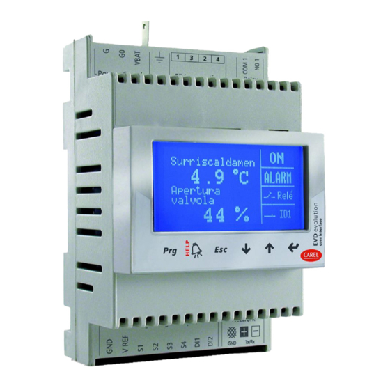
Carel EVD evolution User Manual
Electronic expansion valve driver
Hide thumbs
Also See for EVD evolution
:
User manual
(53 pages)
1
2
3
4
5
Table Of Contents
6
7
8
9
10
11
12
13
14
15
16
17
18
19
20
21
22
23
24
25
26
27
28
29
30
31
32
33
34
35
36
37
38
39
40
41
42
43
44
45
46
47
48
49
page
of
49
Go
/
49
Contents
Table of Contents
Troubleshooting
Bookmarks
Table of Contents
Table of Contents
Introduction
Models
Functions and Main Characteristics
Installation
DIN Rail Assembly and Dimensions
Description of the Terminals
Connection Diagram - Superheat Control
Installation
Connecting the USB-Tlan Converter
Upload, Download and Reset Parameters (Display)
General Connection Diagram
User Interface
Assembling the Display Board (Accessory)
Display and Keypad
Display Mode (Display)
Programming Mode (Display)
Commissioning
Guided Commissioning Procedure (Display)
Checks after Commissioning
Other Functions
Control
Main and Auxiliary Control
Superheat Control
Special Control
Auxiliary Control
Functions
Inputs and Outputs
Control Status
Special Control Status
Protectors
Parameters Table
Unit of Measure
Variables Shown on the Display
Variables Only Accessible Via Serial Link
Alarms
Alarm Relay Configuration
Sensor Alarms
Control Alarms
EEV Motor Alarm
Plan Error Alarm
LAN Error Alarm (for Tlan and Rs485/Modbus® Driver)
Troubleshooting
Technical Specifications
Appendix: Vpm (Visual Parameter Manager)
Installation
Programming (VPM)
Copying the Setup
Setting the Default Parameters
Updating the Driver and Display Firmware
Advertisement
Quick Links
1
Table of Contents
2
Models
3
Troubleshooting
Download this manual
Table of
Contents
Previous
Page
Next
Page
1
2
3
4
5
Advertisement
Table of Contents
Need help?
Do you have a question about the EVD evolution and is the answer not in the manual?
Ask a question
Questions and answers
Related Manuals for Carel EVD evolution
DC Drives Carel EVD evolution User Manual
Electronic expansion valve driver (53 pages)
Controller Carel EASY DRYER Quick Start Manual
Electronic controller for compressed air dryers (2 pages)
Controller Carel easy way aria User Manual
Completely wireless carel solution for the management of ambient comfort in buildings (44 pages)
Controller Carel easy wide User Manual
Electronic controller (56 pages)
Controller Carel ir33+ small wide User Manual
Electronic controller (56 pages)
Controller Carel EVD4 User Manual
Pid controller complete with driver for stepper motors specially designed for the management of electronic expansion valves in refrigerant circuits. (48 pages)
Controller Carel EVD Evolution Twin User Manual
Driver for 2 electronic expansion valves (68 pages)
Controller Carel EVD mini User Manual
Superheat control for unipolar electronic expansion valve (36 pages)
Controller Carel e-drofan User Manual
Electronic controller (60 pages)
Controller Carel EASY COOL Manual
Electronic controllers for normal temperature static refrigeration units (2 pages)
Controller Carel Easy PJEZS Series Manual
(2 pages)
Controller Carel EASY FREEZE Quick Start Manual
Electronic controllers for low temperature ventilated refrigeration units (2 pages)
Controller Carel EVDIS00DE0 User Manual
Electronic expansion valve driver (49 pages)
Controller Carel EVDIS00EN0 User Manual
Electronic expansion valve driver (49 pages)
Controller Carel EVDIS00ES0 User Manual
Electronic expansion valve driver (49 pages)
Controller Carel EVD200 Quick Start Manual
Expansion valve driver (stepper bipolar) (2 pages)
This manual is also suitable for:
Evd0000e00
Evd0000e10
Evd0000e20
Evd0000e01
Evd0000e11
Evd0000e21
...
Show all
Evdis00de0
Evdis00en0
Evdis00es0
Evdis00fr0
Evdis00it0
Evdis00pt0
Evdcon0021
Table of Contents
Save PDF
Print
Rename the bookmark
Delete bookmark?
Delete from my manuals?
Login
Sign In
OR
Sign in with Facebook
Sign in with Google
Upload manual
Upload from disk
Upload from URL


Need help?
Do you have a question about the EVD evolution and is the answer not in the manual?
Questions and answers