
Related Manuals for Carel EVD mini


Summary of Contents for Carel EVD mini
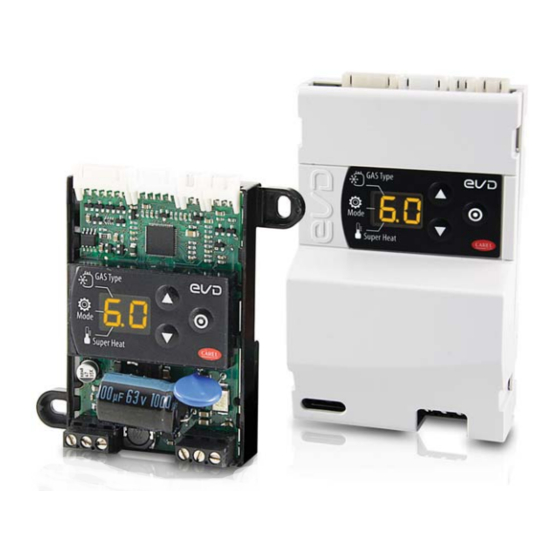
- Page 1 EVD mini Superheat control for unipolar electronic expansion valve User manual NO POWER & SIGNAL CABLES TOGETHER READ CAREFULLY IN THE TEXT! H i g h E f f i c i e n c y S o l u t i o n s...
- Page 3 The technical specifications shown in the manual may be changed without cables in the same conduits. prior warning. NO POWER The liability of CAREL in relation to its products is specified in the CAREL general & SIGNAL contract conditions, available on the website www.carel.com and/or by CABLES specific agreements with customers;...
-
Page 5: Table Of Contents
9.1 Types of alarms ....................30 9.2 Probe alarms ....................30 9.3 Control alarms ....................30 9.4 Valve emergency closing procedure ............30 9.5 Network alarm ....................31 9.6 Alarm table ..................... 31 10. TROUBLESHOOTING 11. TECHNICAL SPECIFICATIONS “EVD mini” +0300036EN - rel. 1.2 - 23.04.2018... -
Page 7: Introduction
1. INTRODUCTION EVD mini is a range of drivers designed for the control of CAREL single- The ratiometric pressure probe specified as default for assembly is P/N pole electronic expansion valves used in refrigerant circuits. EVD SPKT0013P0, with an operating range from -1 to 9.3 barg. Alternatively,... -
Page 8: Installation
(Ø < 4mm). Then tighten the fastening screws. 70,7 (2.78) 42,7 (1.68) Fig. 2.b GAS Typ e Mo de Sup er Hea t Ø 4 (0.2) 7 4 ,1 0 ( 2 .9 ) Fig. 2.e “EVD mini” +0300036EN - rel. 1.2 - 23.04.2018... -
Page 9: Description Of The Terminals
Connection for superheat control with 2 temperatu- USB – RS485 Converter re probes Power supply, 24 V ac Power supply, 0 V ac (24 Vac power Digital input to enable control supply) Tab. 2.a “EVD mini” +0300036EN - rel. 1.2 - 23.04.2018... -
Page 10: Wiring Diagram For Superheat Control
For installation, proceed as shown below, with reference to the wiring • EVD mini requires the use of an evaporation pressure probe S1 and diagrams and the technical specifications table: suction temperature probe S2, which will be fitted downstream of connect the probes: these can be installed up to a maximum the evaporator, and a digital input to enable control. -
Page 11: Copy Parameters With Programming Key
To remove the cover of the display: • *EVD mini/ice is a controller to be incorporated into the final 1 Press with a screwdriver as shown in the figure, to remove the cover. equipment; it must not be wall-mounted;... -
Page 12: User Interface
0 to 10 are displayed with decimal point and decimals; values greater than 99 are displayed in two steps: - first, the hundreds, followed by “H” - then the tens and units. “EVD mini” +0300036EN - rel. 1.2 - 23.04.2018... -
Page 13: Commissioning
10. Press PRG/Set for 2 s to save the settings, exit programming mode Press UP/DOWN to modify the value and activate control. The standard display is shown. GAS Type Mode Super Heat “EVD mini” +0300036EN - rel. 1.2 - 23.04.2018... - Page 14 Note: take into consideration the unit of measure (K/°F) when setting the superheat set point. Superheat set point 11 K(20°F) Bypass pressure set point 3 bar Bypass temperature set point 10 °C “EVD mini” +0300036EN - rel. 1.2 - 23.04.2018...
-
Page 15: Functions
5. FUNCTIONS 5.1 Control EVD mini is a superheat controller and can be used as an analogue positioner. The type of refrigeration unit can be selected using the “Operating mode” parameter. Parameter/description Def. Operating mode 1 = multiplexed cabinet/cold room... -
Page 16: Analogue Positioner (0-10 Vdc)
PID proport. gain PID integral time EVD mini Note: when selecting the type of Mode, the PID control values suggested by CAREL will be automatically set for each application. Control parameters for protection functions See chapter on “Protectors”. Fig. 5.e... -
Page 17: Special Functions
PI control algorithm based on the actual control temperature. Par. Description Def Min The master controller (connected via serial to EVD mini), through Hot gas bypass pressure -20(290) 200(2900) bar(psig) dynamic management of the Smooth_line parameter, modifies the... -
Page 18: Control Parameters For Protection Functions
12 = Ratiometric (OUT=0-5V) 0-60 barg 13 = Ratiometric (OUT=0-5V) 0-90 barg 14 = Remote pressure probe from RS485 Note: the maximum and minimum limits for the pressure probe alarm can be set. See the parameter table. “EVD mini” +0300036EN - rel. 1.2 - 23.04.2018... -
Page 19: Protectors
The LowSH threshold must be less than or equal to the superheat set point. The low superheat integration time indicates the intensity of the action: the lower the value, the more intense the action. “EVD mini” +0300036EN - rel. 1.2 - 23.04.2018... - Page 20 MOP threshold, the more intensely the valve will close. The integration time indicates the intensity of the action: the lower the value, the more intense the action. “EVD mini” +0300036EN - rel. 1.2 - 23.04.2018...
-
Page 21: Parameters Table
5 = 0.85…34.2 barg 12 = Ratiometric (OUT=0-5V) 0-60 barg 6 = 0…34.5 barg 13 = Ratiometric (OUT=0-5V) 0-90 barg 7 = 0…45 barg 14 = Remote pressure probe from RS485 Network address “EVD mini” +0300036EN - rel. 1.2 - 23.04.2018... - Page 22 2=control backup Reserved Pressure S1: MINIMUM alarm value Pressure barg (-121) S1: MAX (psig) alarm value Pressure S1: MAXIMUM alarm value Pressure 200 (392) barg S1: MIN (psig) alarm value Tab. 7.a “EVD mini” +0300036EN - rel. 1.2 - 23.04.2018...
-
Page 23: Network Connection
Programming The RS485 converter is used to connect a computer running the VPM software to the EVD mini driver via a serial network, for commissioning When opening the program, the device to be configured needs to be the controllers. The system allows a maximum of 99 units, with a selected: EVD mini. -
Page 24: Restore Default Parameters
Select list of parameters and then Upload to controller Upload firmware Select firmware and Upload Synoptic and graphs Overview with position of probes and probe and superheat readings in real Fig. 8.h time Tab. 8.b “EVD mini” +0300036EN - rel. 1.2 - 23.04.2018... -
Page 25: Setup Using Configuration File
NAME.hex”. To load and display a list saved by the user, select “Load” and navigate to the path where the file is saved. On the other hand, to load a list of parameters supplied by CAREL, select “Load” and Fig. 8.j... -
Page 26: Variables Accessible Via Serial Connection
MOP: threshold LOP_th- par. C5 reshold (392) MOP_Ti MOP: integral time par. C6 Low_Suct_alarm_threshold Low suction temperature alarm threshold -50(-58) -85(-121) 200(392) par. C8 Mop_Inhibition_threshold MOP: inhibition threshold 30 (86) (-121) (392) “EVD mini” +0300036EN - rel. 1.2 - 23.04.2018... -
Page 27: Control States
Forced closing is performed after the driver is powered on and corresponds Opening (%)= (Valve opening at start-up) x (Current unit cooling to the typical number of closing steps for CAREL E2V and E3V unipolar valves. capacity), where the current unit cooling capacity is sent to the driver This is used to realign the valve to the physical position corresponding to via RS485 by the pCO controller. -
Page 28: Special Control States
The stop procedure involves closing the valve from the current position until reaching 0 steps, plus a further number of steps so as to guarantee complete closing. Following the stop phase, the valve returns to standby. “EVD mini” +0300036EN - rel. 1.2 - 23.04.2018... - Page 29 Note: the valve unblock procedure is nonetheless performed in each of these cases, given that it does not cause mechanical or control problems. Therefore, also check these possible causes before replacing the valve. “EVD mini” +0300036EN - rel. 1.2 - 23.04.2018...
-
Page 30: Alarms
Example: the display shows probe alarms A1 and A2 in sequence. The superheat value has exceeded the maximum limit allowed, and this is The following description only applies if EVD mini is connected to the indicated by the two top segments. -
Page 31: Network Alarm
Press PRG/Set or set the corresponding supervisor variable to 0 on steady EEPROM operating and/or unit parame- Replace the Total shutdown Replace the driver/Contact service ters damaged driver/ Contact service Tab. 9.d “EVD mini” +0300036EN - rel. 1.2 - 23.04.2018... -
Page 32: Troubleshooting
Apply a “soft start” technique, activating the utilities one at a time or in small groups. If or extreme transitory conditions at start-up this is not possible, decrease the values of the MOP thresholds on all the utilities. (for cabinets only). “EVD mini” +0300036EN - rel. 1.2 - 23.04.2018... - Page 33 Check the connection of the digital input. Check that when the control signal is sent cabinets only) does not start control and the valve that the input is closed correctly. Check that the driver is in stand-alone mode. remains closed “EVD mini” +0300036EN - rel. 1.2 - 23.04.2018...
-
Page 34: Technical Specifications
(EN55014-1/EN61000-6-3) with the controller not installed inside a me- tallic panel, fit the ferrite (P/N 0907879AXX • for EVD mini 24 V: applied on the valve stator cable if using in domestic/ residential environments with valve cable > 0.5 m; •... - Page 36 Agenzia / Agency: CAREL INDUSTRIES HeadQuarters Via dell’Industria, 11 - 35020 Brugine - Padova (Italy) Tel. (+39) 049.9716611 - Fax (+39) 049.9716600 e-mail: carel@carel.com - www.carel.com...
Need help?
Do you have a question about the EVD mini and is the answer not in the manual?
Questions and answers