Pepperl+Fuchs LVL-M4 Manual
Vibration limit switch
Hide thumbs
Also See for LVL-M4:
- Technical information (80 pages) ,
- Brief instructions (40 pages) ,
- Instruction manual (2 pages)
Table of Contents
Advertisement
Quick Links
Advertisement
Table of Contents

Subscribe to Our Youtube Channel
Related Manuals for Pepperl+Fuchs LVL-M4


Summary of Contents for Pepperl+Fuchs LVL-M4
- Page 1 LVL-M4 Vibration Limit Switch Manual ISO9001...
- Page 2 Phone: +49 621 776 - 0 E-mail: info@de.pepperl-fuchs.com North American Headquarters Pepperl+Fuchs Inc. 1600 Enterprise Parkway Twinsburg, Ohio 44087 Phone: +1 330 425-3555 E-mail: sales@us.pepperl-fuchs.com Asia Headquarters Pepperl+Fuchs Pte. Ltd. P+F Building 18 Ayer Rajah Crescent Singapore 139942 Phone: +65 6779-9091 E-mail: sales@sg.pepperl-fuchs.com https://www.pepperl-fuchs.com...
-
Page 3: Table Of Contents
Vibration Limit Switch LVL-M4 Contents Introduction ............5 Content of this Document . - Page 4 Vibration Limit Switch LVL-M4 Contents Commissioning ........... 40 Function Check .
-
Page 5: Introduction
Vibration Limit Switch LVL-M4 Introduction Introduction Content of this Document This document contains information that you need in order to use your product throughout the applicable stages of the product life cycle. These can include the following: • Product identification •... -
Page 6: Safety Information
Vibration Limit Switch LVL-M4 Introduction Safety Information Target Group, Personnel Responsibility for planning, assembly, commissioning, operation, maintenance, and dismounting lies with the plant operator. Only appropriately trained and qualified personnel may carry out mounting, installation, commissioning, operation, maintenance, and dismounting of the product. The personnel must have read and understood the instruction manual and the further documentation. - Page 7 Vibration Limit Switch LVL-M4 Introduction Informative Symbols Note This symbol brings important information to your attention. Action This symbol indicates a paragraph with instructions. You are prompted to perform an action or a sequence of actions. ▶ Reference to another section or to further documentation Permitted Procedures, processes or actions that are permitted.
-
Page 8: Registered Trademarks
Bluetooth ® ® The Bluetooth word mark and logos are registered trademarks owned by the Bluetooth SIG, Inc. and any use of such marks by Pepperl+Fuchs is under license. Other trademarks and trade names are those of their respective owners. -
Page 9: Basic Safety Instructions
Vibration Limit Switch LVL-M4 Basic Safety Instructions Basic Safety Instructions Requirements for Personnel The personnel must fulfill the following requirements to carry out the necessary tasks, e. g. commissioning and maintenance: • Trained, qualified specialists must have a relevant qualification for the specific function •... -
Page 10: Operational Safety
The device meets general safety standards and legal requirements. It also complies with the EU directives listed in the device-specific EU Declaration of Conformity. Pepperl+Fuchs confirms this by affixing the CE mark to the device. Functional Safety SIL (Optional) The functional safety manual must be strictly observed for devices that are used in functional safety applications. -
Page 11: Product Description
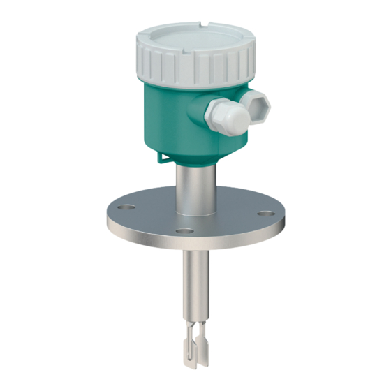
Vibration Limit Switch LVL-M4 Product Description Product Description Vibration limit switch for all liquids, for minimum or maximum detection in tanks, vessels and pipes. Product Design Figure 3.1 Product design ® Housing with electronic insert and cover, optional Bluetooth module or LED module... -
Page 12: Incoming Acceptance And Product Identification
Vibration Limit Switch LVL-M4 Incoming Acceptance and Product Identification Incoming Acceptance and Product Identification Incoming Acceptance Check the following during goods acceptance: □ Are the order codes on the delivery note and the product sticker identical? □ Are the goods undamaged? □... -
Page 13: Storage And Transport
Vibration Limit Switch LVL-M4 Incoming Acceptance and Product Identification Storage and Transport 4.3.1 Storage Conditions Use original packaging. 4.3.2 Storage Temperature • -40 to +80 °C (-40 to +176 °F) • optional: -50 °C (-58 °F), -60 °C (-76 °F) 4.3.3... -
Page 14: Mounting
Vibration Limit Switch LVL-M4 Mounting Mounting Warning! Loss of protection rating if the device is opened in a wet environment. Only open the device in a dry environment! Mounting Instructions • Any orientation for device with short pipe up to approx. 500 mm (19.7 inch) •... -
Page 15: Mounting Requirements
Vibration Limit Switch LVL-M4 Mounting Mounting Requirements 5.1.1 Take Switch Point into Consideration The following are typical switch points, depending on the orientation of the device: water +23 °C (+73 °F) Note Minimum distance between the fork tip and the tank wall or pipe wall: 10 mm (0.39 inch) Figure 5.2... - Page 16 Vibration Limit Switch LVL-M4 Mounting High Viscosity Note Highly viscous liquids may cause switching delays. • Make sure that the liquid can run off the tuning fork easily. • Deburr the socket surface. Note High viscosity, e.g. viscous oils: < 10000 mPa·s The tuning fork must be located outside the installation socket! >...
- Page 17 Vibration Limit Switch LVL-M4 Mounting 5.1.4 Take Clearance into Consideration Allow sufficient space outside the tank for mounting, connection and settings involving the electronic insert. Figure 5.6 Take clearance into consideration 5.1.5 Support the Device Support the device in the event of severe dynamic load. Maximum lateral loading capacity of the pipe extensions and sensors: 75 Nm (55 lbf foot).
-
Page 18: Mounting The Device
Vibration Limit Switch LVL-M4 Mounting 5.1.6 Weld-in Adapter with Leakage Hole Weld in the weld-in adapter in such a way that the leakage hole is pointing downwards. This enables any leaks to be detected quickly. Figure 5.8 Weld-in adapter with leakage hole... - Page 19 Vibration Limit Switch LVL-M4 Mounting Installing in pipes • Flow velocities up to 5 m/s at a viscosity of 1 mPa·s and density 1 g/cm (SGU). Check for correct functioning in the event of other process medium conditions. • The flow will not be significantly impeded if the tuning fork is correctly aligned and the marking is pointing in the direction of flow.
-
Page 20: Sliding Sleeves
Vibration Limit Switch LVL-M4 Mounting Aligning the Cable Entry Note The locking screw is not tightened when the device is delivered. Aligning the Cable Entry Loosen the external locking screw (maximum 1.5 turns). Turn the housing, align the cable entry. -
Page 21: Electrical Connection
Vibration Limit Switch LVL-M4 Electrical Connection Electrical Connection Required Tools • Screwdriver for electrical connection • Allen key for screw of cover lock Connection Requirements 6.1.1 Cover with Securing Screw In the case of devices for use in the hazardous area with a certain type of protection, the cover is sealed by a securing screw. -
Page 22: Connecting The Device
Vibration Limit Switch LVL-M4 Electrical Connection Connecting the Device Caution! Housing thread The thread of the electronics and connection compartment is coated with lubricant varnish. Avoid additional lubrication. 6.2.1 2-wire AC (Electronic Insert FEL61) • 2-wire AC version • Switches the load directly into the power supply circuit via an electronic switch;... - Page 23 Vibration Limit Switch LVL-M4 Electrical Connection Terminal Assignment Always connect an external load. The electronic insert has integrated short-circuit protection. U 19...253 V AC I max: 350 mA >0,7 >0,5 L1 N Figure 6.2 2-wire AC, electronic insert FEL61 Behavior of Switch Output and Signaling ΔU...
- Page 24 Vibration Limit Switch LVL-M4 Electrical Connection Selection Tool for Relays 207 230 253 Figure 6.4 Recommended minimum holding power/rated power for load Holding power/rated power in VA Operating voltage in V AC Mode • Operating voltage: 24 V, 50 Hz/60 Hz •...
- Page 25 Vibration Limit Switch LVL-M4 Electrical Connection 6.2.2 3-Wire DC-PNP (Electronic Insert FEL62) • 3-wire DC version • Preferably in conjunction with programmable logic controllers (PLC), DI modules as per EN 61131-2. Positive signal at switch output of electronics module (PNP) •...
- Page 26 Vibration Limit Switch LVL-M4 Electrical Connection Overvoltage protection Overvoltage category II Terminal Assignment U = 10...55 V DC 350 mA I max: 350 mA 55 V >0,7 >0,5 0.5 A L+ L- Figure 6.5 3-wire DC-PNP, electronic insert FEL62 Connection wiring with terminals...
- Page 27 Vibration Limit Switch LVL-M4 Electrical Connection 6.2.3 Universal Current Connection with Relay Output (Electronic Insert FEL64) • Switches the loads via 2 volt-free changeover contacts • 2 galvanically isolated changeover contacts (DPDT), both changeover contacts switch simultaneously. • Functional testing without level change. A functional test can be performed on the device using the test key on the electronic insert or using the test magnet (can be ordered as an option) with the housing closed.
- Page 28 Vibration Limit Switch LVL-M4 Electrical Connection Terminal Assignment >0,7 U = 19...55 V DC >0,5 U 19...253 V AC 0.5 A Figure 6.7 Universal current connection with relay output, electronic insert FEL64 When bridged, the relay output works with NPN logic...
- Page 29 Vibration Limit Switch LVL-M4 Electrical Connection 6.2.4 DC Connection, Relay Output (Electronic Insert FEL64DC) • Switches the loads via 2 volt-free changeover contacts • 2 galvanically isolated changeover contacts (DPDT), both changeover contacts switch simultaneously. • Functional testing without level change. Functional testing of the entire device can be performed using the test key on the electronic insert or with the test magnet (can be ordered as an option) with the housing closed.
- Page 30 Vibration Limit Switch LVL-M4 Electrical Connection Terminal Assignment >0,7 >0,5 U = 9...20 V DC 0.5 A L- PE Figure 6.9 DC connection with relay output, electronic insert FEL64DC When bridged, the relay output works with NPN logic Connectable load Behavior of Switch Output and Signaling Figure 6.10...
- Page 31 Vibration Limit Switch LVL-M4 Electrical Connection 6.2.5 2-Wire NAMUR > 2.2 mA/< 1.0 mA (Electronic Insert FEL68) • To connect to switch amplifiers according to NAMUR (IEC 60947-5-6), a permanent power supply for the electronic insert must be ensured. •...
- Page 32 Vibration Limit Switch LVL-M4 Electrical Connection Terminal Assignment IEC 60947-5-6 8,2 V DC NAMUR – >0,7 >0,5 L+ L- PE L- L+ Figure 6.11 2-wire NAMUR > 2.2 mA/< 1.0 mA, electronic insert FEL68 Connection wiring with terminals Connection wiring with M12 plug in housing according to EN 61131-2 Behavior of Switch Output and Signaling 2.2...3.8 mA...
- Page 33 Vibration Limit Switch LVL-M4 Electrical Connection 6.2.6 LED Module VU120 (optional) Supply Voltage U = 12 to 55 V DC U = 19 to 253 V AC, 50 Hz/60 Hz Power Consumption S < 6 VA, P ≤ 0.7 W Current Consumption = 0.4 A...
- Page 34 Vibration Limit Switch LVL-M4 Electrical Connection Operational Status Signaling Figure 6.14 LED module VU120, the LED lights up in green (GN), yellow (YE) or red (RD) A brightly lit LED indicates the operational status (switch status or alarm status). The LED module can be connected to the following electronic inserts: FEL62, FEL64, FEL64DC.
- Page 35 Vibration Limit Switch LVL-M4 Electrical Connection Batteries – Use and Handling Use of a special battery in conjunction with electronic insert FEL68 (2-wire NAMUR): ® • For energy reasons, the Bluetooth module VU121 requires a special battery when operated with the electronic insert FEL68 (2-wire NAMUR).
- Page 36 Vibration Limit Switch LVL-M4 Electrical Connection ® Connecting the Bluetooth Module Note In the case of devices for use in the hazardous area with a certain type of protection, the cover is sealed by a securing screw. ▶ For more information see chapter 6.1.1.
-
Page 37: Post-Connection Check
Vibration Limit Switch LVL-M4 Electrical Connection 6.2.8 Connecting the Cables Required tools • Flat-blade screwdriver (0.6 mm x 3.5 mm) for terminals • Suitable tool with width across flats AF24/25 (8 Nm (5.9 lbf foot)) for M20 cable gland 24/25 mm 8.0 Nm... -
Page 38: Operation Options
Vibration Limit Switch LVL-M4 Operation Options Operation Options Overview of Operation Options 7.1.1 Operating Concept • Operation with button and DIP switches on the electronic insert ® ® • Display with optional Bluetooth module and P+F Level app via Bluetooth... - Page 39 Vibration Limit Switch LVL-M4 Operation Options ® 7.1.3 Bluetooth Wireless Technology ® Access via Bluetooth wireless technology ® Figure 7.2 Remote operation via Bluetooth wireless technology Mobile phone or tablet with P+F Level app ® Device with optional Bluetooth module ®...
-
Page 40: Commissioning
Vibration Limit Switch LVL-M4 Commissioning Commissioning Function Check Before commissioning the measuring point, check whether the post-installation and post- connection checks have been performed: ▶ Post-mounting check see chapter 5.4 ▶ Post-connection check see chapter 6.3 Functional Test Using the Key on the Electronic Insert •... - Page 41 Vibration Limit Switch LVL-M4 Commissioning 8.2.1 FEL61 Switching Behavior and Signaling <3.8 mA ΔU >1 s <3.8 mA <3.8 mA <3.8 mA Figure 8.2 FEL61 switching behavior and signaling After the test key is pressed, the load is switched off for at least 10 s (I < 3.8 mA) even if the key is pressed for <...
- Page 42 Vibration Limit Switch LVL-M4 Commissioning 8.2.3 FEL64, FEL64DC Switching Behavior and Signaling 3 4 5 6 7 8 3 4 5 6 7 8 >1 s 3 4 5 6 7 8 3 4 5 6 7 8 3 4 5...
-
Page 43: Functional Test Of The Electronic Switch With A Test Magnet
Vibration Limit Switch LVL-M4 Commissioning Functional Test of the Electronic Switch with a Test Magnet Perform functional test of the electronic switch without opening the device: Testing Function Hold the test magnet against the marking on the nameplate on the outside. - Page 44 Vibration Limit Switch LVL-M4 Commissioning Initial Password ® The ID number on the nameplate of the Bluetooth module is used as the initial password when establishing the connection for the first time. Note ® It is important to note the following if the Bluetooth module is removed from one device ®...
- Page 45 Vibration Limit Switch LVL-M4 Commissioning Saving PDF Reports Note The PDF reports generated in the P+F Level app are not automatically saved and must therefore be actively saved on the smartphone or tablet.
-
Page 46: Operation
Vibration Limit Switch LVL-M4 Operation Operation Menu Assembly The following data can be read out via the optional Bluetooth module and the associated Pepperl+Fuchs P+F Level app. 9.1.1 Diagnostics Menu Settings and information concerning diagnostics as well as help for troubleshooting. -
Page 47: Proof Testing For Sil/Whg Devices
Vibration Limit Switch LVL-M4 Operation 9.1.3 System Menu System settings concerning device management, user administration or safety. System Electronic type ▶ Bluetooth configuration BLE HW revision ▶ Information Device tag Serial number Firmware version Device name Order code Manufacturer Manufacturer ID... -
Page 48: Diagnostics And Troubleshooting
Vibration Limit Switch LVL-M4 Diagnostics and Troubleshooting Diagnostics and Troubleshooting ® The device indicates warnings and faults via Bluetooth in the P+F Level app and via the LEDs on the electronic insert. All the device warnings and faults are for information purposes only and do not have a safety function. -
Page 49: Firmware History
Vibration Limit Switch LVL-M4 Diagnostics and Troubleshooting Device is visible in the live list but cannot be accessed via P+F Level App • Possible cause on Android end device Troubleshooting: • Check whether the location function is enabled for the app. -
Page 50: Maintenance
Vibration Limit Switch LVL-M4 Maintenance Maintenance No special maintenance work is required. 11.1 Maintenance Tasks 11.1.1 Cleaning It is not permitted to use the device with abrasive media. Material abrasion on the tuning fork can result in the device malfunctioning. -
Page 51: Repair
The device must be returned if the wrong device has been ordered or delivered. As an ISO- certified company and also due to legal regulations, Pepperl+Fuchs is obliged to follow certain procedures when handling any returned products that have been in contact with medium. -
Page 52: Disposal
WEEE as unsorted municipal waste. Do not dispose of products bearing this marking as unsorted municipal waste. Instead, return them to Pepperl+Fuchs for disposal under the applicable conditions. -
Page 53: Accessories
Vibration Limit Switch LVL-M4 Accessories Accessories 13.1 Enclosed Accessories These accessories can be ordered together with the device or can be ordered separately. 13.1.1 Test Magnet Order number: 71580748 Figure 13.1 Test magnet 13.1.2 Weather Protection Cover for Dual-Compartment Housing, Aluminum... -
Page 54: Additional Accessories
Vibration Limit Switch LVL-M4 Accessories 13.1.3 Protective Cover for Single Compartment Housing, Aluminum or 316L Material: plastic Order number: 71580796 115 (4.53) 140 (5.51) 32 (1.26) Figure 13.3 Protective cover for single compartment housing, aluminum or 316L, unit of measurement mm (inch) 13.2... - Page 55 Vibration Limit Switch LVL-M4 Accessories ® 13.2.2 Bluetooth Module VU121 (optional) ® The Bluetooth module can be connected to the following electronic inserts via the COM interface: FEL61, FEL62, FEL64, FEL64DC, FEL68 (2-wire NAMUR). ® • Bluetooth module owithout battery for use in conjunction with electronic inserts FEL61,...
- Page 56 Vibration Limit Switch LVL-M4 Accessories 13.2.3 Female Cordset V1-W-5M-PVC • Interfaces • Connector, socket, M12, angled, A-coded • Cable 5 m (16 foot) • Ambient temperature • Connector: -40 to 90 °C (-40 to 194 °F) • Cable, fixed: -25 to 70 °C (-13 to 158 °F) •...
- Page 57 Vibration Limit Switch LVL-M4 Accessories 13.2.4 Sliding Sleeves for Unpressurized Operation Switch point, infinitely adjustable. M6 (3x) M6 (3x) G1½ A (1 NPT) (1½ NPT) Figure 13.7 Sliding sleeves for unpressurized operation p = 0 bar (0 psi), unit of measurement...
- Page 58 Vibration Limit Switch LVL-M4 Accessories 13.2.5 High Pressure Sliding Sleeves • Switch point, infinitely adjustable • Use in hazardous areas • Seal package made of graphite • Graphite seal available as spare part 71078875 • In the case of G1, G1-1/2: seal is included in the delivery Ø60 (2.36)
- Page 59 Vibration Limit Switch LVL-M4 Accessories G1-1/2, DIN ISO 228/1 • Material: Alloy C22 • Weight: 1.32 kg (2.91 lb) • Approval: with inspection certificate EN 10204 - 3.1 material • Order number: 71118693 NPT1-1/2, ASME B 1.20.1 • Material: 1.4435 (AISI 316L) •...
-
Page 60: Technical Data
Vibration Limit Switch LVL-M4 Technical Data Technical Data 14.1 Input 14.1.1 Measured Variable Level (point level), MAX or MIN safety 14.1.2 Measuring Range Depends on the installation location and the pipe extension ordered Maximum sensor length 6 m (20 foot) 14.2... -
Page 61: Environment
14.2.3 Safety-Related Connection Data See safety instructions (SI): All data relating to explosion protection are provided in separate Ex documentation and are available from the product detail page of the Pepperl+Fuchs website. Enter the order designation in the search field Select the appropriate product →... - Page 62 Vibration Limit Switch LVL-M4 Technical Data T amb T amb [°F] [°C] T amb +120 +150 [°C] [°F] +194 +248 +302 Figure 14.1 Permitted ambient temperature T at the housing as a function of the process temperature T in the vessel: Device without LED module, at process temperature and FEL64 T >...
- Page 63 Vibration Limit Switch LVL-M4 Technical Data 14.3.3 Humidity Operation up to 100 %. Do not open in a condensing atmosphere. 14.3.4 Operating Altitude According to IEC 61010-1 Ed.3: • Up to 2000 m (6600 foot) above sea level • Can be extended to 3000 m (9800 foot) above sea level if overvoltage protection is used.
-
Page 64: Process
In each case, the lowest value from the derating curves of the device and the selected flange applies. Note Devices with CRN approval: maximum 90 bar (1305 psi) for devices with a pipe extension. Additional information on the Pepperl+Fuchs website: www.pepperl-fuchs.com. - Page 65 Vibration Limit Switch LVL-M4 Technical Data Process Pressure Range of the Sensors [psi] [bar] 1450 +150 [°C] [°F] +302 Figure 14.2 Process temperature Permitted pressure rating if the following option is selected: Type code, feature Application, temperature, Option B, 100 bar (1450 psi).
-
Page 66: Additional Technical Data
Vibration Limit Switch LVL-M4 Technical Data 14.4.6 Viscosity ≤ 10000 mPa·s 14.4.7 Pressure Tightness Up to vacuum Note In vacuum evaporation plants: select the 0.4 g/cm density setting. 14.4.8 Solids Contents Ø ≤ 5 mm (0.2 inch) 14.5 Additional Technical Data... -
Page 67: Index
Vibration Limit Switch LVL-M4 Index Bluetooth module ................39 Bluetooth wireless technology . - Page 68 Vibration Limit Switch LVL-M4 Index Repair concept ................51 Replacing a device .
- Page 69 Vibration Limit Switch LVL-M4 Notes...
- Page 70 Pepperl+Fuchs Quality Download our latest policy here: www.pepperl-fuchs.com/quality BA01894O/98/EN/04.22 www.pepperl-fuchs.com © Pepperl+Fuchs · Subject to modifications Printed in Germany / DOCT-8107...
Need help?
Do you have a question about the LVL-M4 and is the answer not in the manual?
Questions and answers