
Related Manuals for Power Fist 8273757


Summary of Contents for Power Fist 8273757
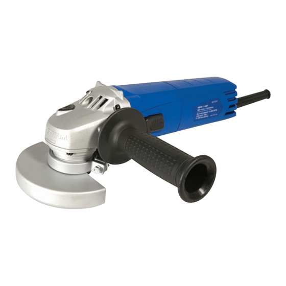
- Page 1 Angle Grinder 8273757 OWNER'S MANUAL Please read and understand all instructions before use. Retain this manual for future reference.
-
Page 2: Angle Grinder
8273757 Angle Grinder INTRODUCTION Read and save this instruction manual. Tool specifications: Model Voltage (V) Frequency (Hz) Rated Current (A) No-load speed (Min-1) Disc dia. Spindle Bore Weight (kg) CH3301 120 11000 4-1/2“ 5/8“-11UNC SPECIFICATIONS Input power: 1,200 W - 9 Amps Electric current voltage 120±10% VAC... -
Page 3: Electrical Safety
8273757 5. Use clamps or other practical ways to secure and support the work piece to a stable platform. Holding the work piece by hand or against your body is unstable and may lead to loss of control. TOOL USE AND CARE 1. -
Page 4: Specific Safety Instructions
8273757 9. Always position the cord so that it will not be caught in the workpiece when the grinder is in use. Position the tool so that the power cord always stays behind the machine during operation. Keep the power cord away from the work area during use. -
Page 5: Kickback And Related Warnings
8273757 29. Do not use accessories that require liquid coolants. Using water or other liquid coolants may result in electrocution or shock. This tool is intended for grinding, cutting and deburring metal materials without the use of water. 31. Do not apply pressure on the tool; let the speed of the cutting disc do the work. - Page 6 8273757 Figure 6 Stop the tool by pressing the button of on/off switch. SPEED CONTROLLER ACTION The tool speed can be changed by turning the speed controller (6) to a given number setting from 1 to 6 (at the time when the on/off switch is fully pulled).
-
Page 7: Cutting Operation
8273757 CAUTION: An O-ring is inserted in the inner flange around the spigot. If the O-ring is missing or is damaged , it must in all cases be replaced before the inner flange is mounted. 6. Place the grinding(10) or cutting disc (11 )on the top of the inner flange ensuring the bore fits into the step of the flange. - Page 8 8273757 protruding wheel may cut gas or water pipes, electrical wiring or objects that can cause kickback. GRINDING AND SANDING OPERATION 1. In general, keep the edge of the wheel or disc at an angle of about 30° to 40° to the work-piece surface.
- Page 9 8273757 DIAGRAM PDF 文件使用 "FinePrint pdfFactory Pro" 试用版本创建 www.fineprint.com.cn For any technical questions, please call 1-800-665-8685...
-
Page 10: Parts List
8273757 PARTS LIST Description Description Outer flange Ball Bearing 6000.2RS O-ring Bearing cover Inner Flange Armature Grinding guard Dustproof ring Hex. nut M5 Ball Bearing 608.2Z Spring lock washer Bearing bush Square washer Baffle Guard trigger Topping Screw ST4X70C Pan head screw M4X14...
Need help?
Do you have a question about the 8273757 and is the answer not in the manual?
Questions and answers