Table of Contents
Advertisement
Quick Links
Advertisement
Table of Contents

Related Manuals for Array Solutions PowerMaster Series


Summary of Contents for Array Solutions PowerMaster Series
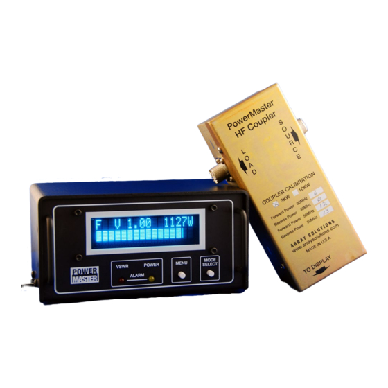
- Page 1 PowerMaster Series Digital RF Power &V.S.W.R. Indicator Array Solutions 350 Gloria Rd Sunnyvale, TX 75182 www.arraysolutions.com phone 972 203 2008 e-mail sales@arraysolutions.com Manufactured in the U.S.A. PowerMaster Series RF Wattmeter Array Solutions Rev 3.5 Feb 20, 2007...
- Page 2 INTRODUCTION Thank you very much for purchasing the Array Solutions PowerMaster available for download from the Array Solutions website as they become Series RF Power/VSWR Indicator. The PowerMaster represents a available. This means that the user can take full advantage of features or breakthrough in features for measurement of the performance of your enhancements just by installing the firmware update.
- Page 3 Properly shielded and grounded cables and connectors must be used generates, uses, and can radiate radio frequency energy, and if not in order to meet FCC emission limits. Array Solutions is not installed and used in accordance with the instructions may cause responsible for any radio or television interference caused by using harmful interference to radio communications.
- Page 4 Array Solutions and PowerMaster RF Power/VSWR Wattmeter are trademarks of Array Solutions The firmware for the PowerMaster series is copyrighted. ©2005 by Array Solutions. All rights reserved. The application software for the PowerMaster is copyrighted. ©2005 by D. Kinsell, All rights reserved.
-
Page 5: Table Of Contents
Rear Panel Connections Page 18 Remote Coupler Mounting Page 19 Accuracy and Calibration Page 20 Options Page 22 In Case of Trouble Page 23 Specifications Page 24 Warranty Page 25 PowerMaster Series RF Wattmeter Array Solutions Rev 3.5 Feb 20, 2007... -
Page 6: Unpacking And Setup
• Make sure your power source can supply at least 600 ma of current. • Please do not use a cheap wall wart. These devices are usually not regulated and may cause RFI. PowerMaster Series RF Wattmeter Array Solutions Rev 3.5 Feb 20, 2007... -
Page 7: Quick Setup
This will affect the accuracy of the PowerMaster (just as it would any other measuring device). PowerMaster Series RF Wattmeter Array Solutions Rev 3.5 Feb 20, 2007... -
Page 8: Installation
Connect from your transmitter's antenna jack to the SOURCE connector on the Directional Coupler. PowerMaster Series RF Wattmeter Array Solutions Rev 3.5 Feb 20, 2007... -
Page 9: Using The Powermaster - Front Panel
These buttons are used to select the operational mode, and to program the from the Array Solutions Website. You are invited to join the Array Solutions User’s Group which can be found on the Array Solutions meter’s several functions such as VSWR Alarm, Power Monitor Alarm,... - Page 10 Push the mode select button to select the VSWR alarm trip point: Push the mode select button to reset the VSWR alarm and LED Pushing the menu button again takes us to the next menu. PowerMaster Series RF Wattmeter Array Solutions Rev 3.5 Feb 20, 2007...
- Page 11 1,600 2,600 3,000 If the peak power exceeds this setting the power alarm LED PowerMaster Series RF Wattmeter Array Solutions Rev 3.5 Feb 20, 2007 will flash and the power monitor relay will cycle on and off. If the “Alarm Trips Amp”, next menu, option is selected then the VSWR alarm LED will also flash and the PTT/ALC relay will actuate but will not cycle.
- Page 12 This menu option allows the high power alarm to actuate the PTT/ALC relay just like a VSWR alarm does. Pushing the menu button again takes us to the next menu. PowerMaster Series RF Wattmeter Array Solutions Rev 3.5 Feb 20, 2007...
- Page 13 ALARM OPENS Relay ALARM CLOSES Relay This applies to the PTT/ALC relay only – not the Power Monitor relay Pushing the menu button again takes us to the next menu. PowerMaster Series RF Wattmeter Array Solutions Rev 3.5 Feb 20, 2007...
- Page 14 Pushing the menu button again takes us to the next menu. Display Intensity Menu Select with mode select button: 4 (brightest) Pushing the menu button again takes us to the next menu. PowerMaster Series RF Wattmeter Array Solutions Rev 3.5 Feb 20, 2007...
- Page 15 5% accuracy at 50 MHz if you use the setting in the calibration table for 50 MHz. Pushing the menu button again takes us to the next menu. PowerMaster Series RF Wattmeter Array Solutions Rev 3.5 Feb 20, 2007...
- Page 16 Selects your preferred way you chose to display power and is shown on the digital power readout and bar graph. Pushing the menu button again takes us to the next menu. PowerMaster Series RF Wattmeter Array Solutions Rev 3.5 Feb 20, 2007...
- Page 17 19 minuets. Screen fills with dots when “YES” is selected We recommend doing this about every 6 months or when you notice some dots are weaker then others. PowerMaster Series RF Wattmeter Array Solutions Rev 3.5 Feb 20, 2007...
- Page 18 The meter can have its internal firmware updated from the serial port connected to your PC. Just download the latest revision of firmware from the Array Solutions web site at www.arraysolutions.com. See the LITE or PRO software manuals on the CD for the procedure.
-
Page 19: Rear Panel Connections
PTT IN and PTT OUT – Route PTT through this connector. or an ALC voltage to the amplifier to shut it down fast. .5 amp 50V • contacts. RS232 – connect a DB9 cable to a PC com. port to program and read the meter with the application software. • PowerMaster Series RF Wattmeter Array Solutions Rev 3.5 Feb 20, 2007... -
Page 20: Remote Coupler Mounting
DIRECTIONAL COUPLER CONNECTORS • You may order the unit with SO239 (standard) connectors, Type-N, or 7/16 Din. • The connectors are field replaceable if you should need to do so. PowerMaster Series RF Wattmeter Array Solutions Rev 3.5 Feb 20, 2007... -
Page 21: Accuracy And Calibration
The calibration values are held in non-volatile We provide a calibration table on each directional memory. coupler just like the calibrated sensors we use from our measurement system. The ability to program the PowerMaster Series RF Wattmeter Array Solutions Rev 3.5 Feb 20, 2007... - Page 22 • HP436A micro wattmeter calibrated and traceable to NIST • HP wattmeter sensor with calibration traceable to NIST • Bird 30 dB 2 KW calibrated attenuator traceable to NIST PowerMaster Series RF Wattmeter Array Solutions Rev 3.5 Feb 20, 2007...
-
Page 23: Options
CD ROM or on our web site to update the flash memory in the meter. • Coupler Scanner is a hardware option that will scan up to 8 couplers. PowerMaster Series RF Wattmeter Array Solutions Rev 3.5 Feb 20, 2007... -
Page 24: In Case Of Trouble
Be sure that you have installed the Directional Coupler AHEAD OF the tuner. If your rig has an internal tuner, you should turn it off to make the most accurate measurements. PowerMaster Series RF Wattmeter Array Solutions Rev 3.5 Feb 20, 2007... -
Page 25: Specifications
EMP 4 KV and 8 KV on cables Dimensions Display 8 ¼” X 3 ½ “Face, 4 ¼” Deep Coupler 2 ¾” X 2 ¾” X 6 ½” Shipping Weight 5 lbs (2.3 kg) PowerMaster Series RF Wattmeter Array Solutions Rev 3.5 Feb 20, 2007... -
Page 26: Warranty
WARRANTIES, INCLUDING IMPLIED WARRANTIES OF MERCHANTABILITY AND Array Solutions FITNESS. In no event will Array Solutions be liable for 350 Gloria Rd. consequential damages. Sunnyvale, TX 75182 If you must return the unit to the factory, you must obtain ATTN: Service authorization from the factory.
Need help?
Do you have a question about the PowerMaster Series and is the answer not in the manual?
Questions and answers