Table of Contents
Advertisement
Quick Links
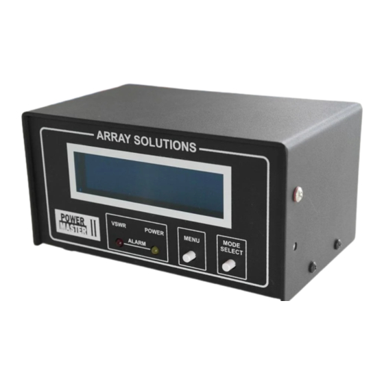
PowerMaster II
Digital RF Power &VSWR Measurement System
Array Solutions · 2611 N Belt Line Rd · Sunnyvale, TX 75182 · USA
http://www.arraysolutions.com · phone +1 214 954-7140 · e-mail sales@arraysolutions.com
Manufactured in the U.S.A.
1
PowerMaster II RF Wattmeter
www.arraysolutions.com
Rev 4.1 - February 23, 2017
Advertisement
Table of Contents

Related Manuals for Array Solutions PowerMaster II


Summary of Contents for Array Solutions PowerMaster II
- Page 1 PowerMaster II Digital RF Power &VSWR Measurement System Array Solutions · 2611 N Belt Line Rd · Sunnyvale, TX 75182 · USA http://www.arraysolutions.com · phone +1 214 954-7140 · e-mail sales@arraysolutions.com Manufactured in the U.S.A. PowerMaster II RF Wattmeter www.arraysolutions.com...
- Page 2 With the ability to monitor your VSWR and power levels at all times, you will know that your transmitter, RF source, and load, or There are many features introduced in the PowerMaster II that have not antenna systems are operating effectively and safely. In addition, the been seen before –...
- Page 3 Write your new PowerMaster serial number and calibration data for your coupler here (see coupler cover) Coupler Calibration Table Serial Number _________________ Forward Power 30MHz Reverse Power 30 MHz Date of purchase _________________ Forward Power 50 MHz Reverse Power 50 MHz PowerMaster II RF Wattmeter www.arraysolutions.com Rev 4.1 - February 23, 2017...
- Page 4 Properly shielded and grounded cables and connectors must be used in installed and used in accordance with the instructions may cause order to meet FCC emission limits. Array Solutions is not responsible harmful interference to radio communications. However, there is no for any radio or television interference caused by using other than guarantee that interference will not occur in a particular installation.
- Page 5 Array Solutions, Power Master, and PowerMaster II are trademarks of Array Solutions The firmware for the PowerMaster II is copyrighted. ©2012 by Array Solutions. All rights reserved. The Power Master Basic II application software for the PowerMaster II is copyrighted. ©2012 by S. London, All rights reserved. PowerMaster II RF Wattmeter www.arraysolutions.com...
-
Page 6: Table Of Contents
Rear Panel Connections Page 11 Remote Coupler Mounting Page 19 Accuracy and Calibration Page 20 Options Page 22 In Case of Trouble Page 23 Specifications Page 24 Warranty Page 25 PowerMaster II RF Wattmeter www.arraysolutions.com Rev 4.1 - February 23, 2017... -
Page 7: Unpacking And Setup
– 6 feet long (We recommend using a separate PS for this cable, not your TXCVR’s) This Manual Please note that we do not ship a software CD ROM with the PowerMaster II. Please go to the Array Solutions website and download the latest version of the software for your PowerMaster II. . -
Page 8: Quick Setup
VSWR number with a bar graph to indicate relative power, you may now proceed to program it from the front panel buttons or the control software. 3 kW or 10 kW HF Coupler VHF and UHF Couplers PowerMaster II RF Wattmeter www.arraysolutions.com Rev 4.1 - February 23, 2017... -
Page 9: Installation
PS feeding your transceiver, to avoid RFI and There is no harm to the Power Master II unit either way. potential malfunction of the PowerMaster II. DIRECTIONAL COUPLER WIRING - Since the purpose of the... - Page 10 The following discussion shows you how to operate the meter. As we add there are two buttons on the front of the PowerMaster II: “Menu” and “Mode more features, you will be able to download more options for your meter from Select.”...
- Page 11 *Note: You may not use both the RS232 and USB connections at the same time. Only connect one to your computer. The RS-232 port is disabled by the firmware when the USB port is active. PowerMaster II RF Wattmeter www.arraysolutions.com...
- Page 12 (C1 – Coupler 1) VSWR Alarm Limit Menu Push the mode select button to select the VSWR alarm trip point: Push the mode select button to reset the VSWR alarm and PowerMaster II RF Wattmeter www.arraysolutions.com Rev 4.1 - February 23, 2017...
- Page 13 If the peak power remains below this setting for a few seconds the power alarm LED will light and the power monitor relay will actuate. Push the mode select button to reset the alarm and LED PowerMaster II RF Wattmeter www.arraysolutions.com Rev 4.1 - February 23, 2017...
- Page 14 This will automatically reset the both the VSWR and Power Alarms or if “Off” will force a manual reset only. Select by pushing the mode select button: 1 second 2 seconds 5 seconds PowerMaster II RF Wattmeter www.arraysolutions.com Rev 4.1 - February 23, 2017...
- Page 15 Bargraph Ranges Menu Select with mode select button: 3 kW Coupler 10 kW Coupler 1000 2500 1250 2500 5000 1000 1700 2000 10000 1000 2000 3000 1000 5000 10000 PowerMaster II RF Wattmeter www.arraysolutions.com Rev 4.1 - February 23, 2017...
- Page 16 Select your preferred method to display power on the digital power readout and bar graph. See the different display formats for 1328 W forward, 26.9 reverse and 1.33 SWR depending on the selected display mode. PowerMaster II RF Wattmeter www.arraysolutions.com Rev 4.1 - February 23, 2017...
- Page 17 Coupler Input 1 to Coupler Input 2. The next menu resumes as normal where you can define the coupler type (See Page 12). Note: The unique settings for each coupler are stored in the Power Master II’s non-volatile memory. PowerMaster II RF Wattmeter www.arraysolutions.com Rev 4.1 - February 23, 2017...
- Page 18 Mode) in this menu. M is shown selected here. ([M]edium retention of peak hold, ~1 second) You can select any of the four Forward Modes when in this menu: F, M, S or L (see page 10 for details). PowerMaster II RF Wattmeter www.arraysolutions.com Rev 4.1 - February 23, 2017...
- Page 19 The first step is to disconnect all connections to the rear panel of your Power Master II and remove the two #6-32 philips screws on either side of the cabinet. Then locate JP1 on the right side of the board. PowerMaster II RF Wattmeter www.arraysolutions.com Rev 4.1 - February 23, 2017...
- Page 20 – not two! This will allow you to transmit through either coupler and the meter will display that transmitter’s output instantly without any switching. If you transmit on both at the same time, whichever one is at a higher power level will be shown. PowerMaster II RF Wattmeter www.arraysolutions.com...
- Page 21 Other useful aspects of the PowerMaster II: VSWR is not displayed if the forward power is less than 1 watt with a 3 kW coupler or 2 watts with a 10 kW coupler. VSWR alarm function is disabled if the forward power is less than 10 Watts in Forward modes or less than 50 Watts in V (Reflected) mode.
-
Page 22: Remote Coupler Mounting
DIRECTIONAL COUPLER CONNECTORS You may order the unit with SO-239 (standard) connectors, Type-N, or 7/16 DIN. The connectors are field replaceable if you should need to do so. PowerMaster II RF Wattmeter www.arraysolutions.com Rev 4.1 - February 23, 2017... -
Page 23: Accuracy And Calibration
ACCURACY AND CALIBRATION PowerMaster with this calibration “trim” data assures you The PowerMaster II resolves 14 equivalent bits of analog to digital data. There are 8 sampling channels: 4 forward that you have the best calibration possible with your and 4 reverse. A calibration table is generated for each meter. - Page 24 HP-436A micro wattmeter calibrated and traceable to NIST HP wattmeter sensor with calibration traceable to NIST Bird 30 dB 2 kW calibrated attenuator traceable to NIST PowerMaster II RF Wattmeter www.arraysolutions.com Rev 4.1 - February 23, 2017...
- Page 25 PowerMaster II RF Wattmeter www.arraysolutions.com Rev 4.1 - February 23, 2017...
-
Page 26: Options
Additional couplers – 3 kW, 10 kW, VHF, UHF and QRP couplers o Firmware updates are announced on the web site and through the Array Solutions user group. Use the Firmware Updater program from our web site to update the flash memory in the meter. -
Page 27: Specifications
EMP 4 kV and 8 kV on cables Display 8 ¼” X 3 ½ “Face, 4 ¼” Deep Dimensions Coupler 2 ¾” X 2 ¾” X 6 ½” Shipping Weight 4 lb (1.8 kg) . PowerMaster II RF Wattmeter www.arraysolutions.com Rev 4.1 - February 23, 2017... -
Page 28: Warranty
WARRANTIES, INCLUDING IMPLIED Array Solutions WARRANTIES OF MERCHANTABILITY AND FITNESS. In no event will Array Solutions be liable for 2611 North Belt Line Road consequential damages. Suite # 109 Sunnyvale, TX 75182 USA If you must return the unit to the factory, you must obtain authorization from the factory.
Need help?
Do you have a question about the PowerMaster II and is the answer not in the manual?
Questions and answers