
Related Manuals for Sproutwell NURSERY GREENHOUSE

Summary of Contents for Sproutwell NURSERY GREENHOUSE
- Page 1 NURSERY GREENHOUSE Assembly Instructions MODEL: NURSERY GREENHOUSE PRODUCT SIZE(LxWxH):107x55x188cm PLEASE READ CAREFULLY BEFORE ASSEMBLY...
- Page 2 Door1 Frame Assembly Body Frame Assembly Roof Frame Assembly PART PART NO. Qty. NO. Qty. PART NO. Qty. L08A L01A L01B L02A L08B L05A L02B L08E L05B L03A L05C L03B L15A L04A L06A L06B Ø4X16D L07A Door2 Frame Assembly PART NO. Qty. L08C Final Assembly PART...
- Page 3 PART NO. Qty. L08A L08B Door1 Frame Assembly L08E...
- Page 4 L08E L08A L08B L08E Adjust the screws in connector D to a horizontal position and insert connector D into L08E, then insert the whole part into L08A & B and tighten them gently. L08E L08E L08E L08B L08A Slide 4 x W02 into each profile, then adjust the screws in connector D to a horizontal position and insert Slide panel Y4 into the channels of each connector D into each profile, tighten them gently.
- Page 5 PART NO. Qty. L08C L08D Door2 Frame Assembly L08E...
- Page 6 L08E L08C L08C L08D L08E REPEAT the assembly of 'Door1 Frame Assembly'. L08E L08E L08E L08D L08C REPEAT the assembly of 'Door1 Frame Assembly'. Slide panel Y4 into the channels of L08C & D and cover Y4 with another L08E to complete the second door.
- Page 7 PART NO. Qty. Vent Frame Assembly Ø4X16D...
-
Page 8: Roof Frame Assembly
PART NO. Qty. L01B L05A L05B L05C L15A Roof Frame Assembly Ø4X16D... - Page 9 L05B Adjust the screws in connector C to a horizontal position and insert connector C into L05B & L01B, then tighten them gently(see Fig.). L01B L01B L01B L01B...
- Page 10 L05A L05C * This pre-fixed J07 is to hold J08 vent supporter. L05C Slide 2 x W02 into each L05A & L05C, then adjust the screws in connector C to a horizontal position and insert connector C into L05A & L05C & L01B,then tighten them gently (see Fig. above).
- Page 11 Put L15A on L05B in place as shown, L05B drill 3 holes on L05B through 3 L15A pre-drilled holes of L15A, Dia.3.2mm, then secure L15A and L05B with Z01.
- Page 12 PART NO. Qty. L01A L02A Body Frame Assembly L02B L03A L03B L04A L06A L06B L07A W02 20 W03 12 M8x60...
- Page 13 L02B L02A L02A L04A Slide 6 x W02 into each profile (2 into the back and 2 into each side),then adjust the screws in connector A & B to a horizontal position and insert connector A & B into each profile,then tighten them gently(see Fig.
- Page 14 Insert panel Y2 into the channel of L02B and push Y2 gently until it touches connector A. L06B Insert L06B into the channel of L02B, then turn it 90 degrees. SO L06B covers the L06B edge of Y2 (see right Fig.) L02B...
- Page 16 L06A Slide in L06A to cover Y2 and L06B,then make sure Y2 and the fixings of L06B are in the channel of L06A at each end.
- Page 17 Slide each W02 into each end of L06A.
- Page 18 L01A L01A Slide in L01A from the top and make sure Y2 and the fixings of L06A are in the channel of L01A(see Fig. above) L03B L03A W02x3 W02x3 Slide in 8 x W02 from the bottom,then adjust the screws in connector A & B to a horizontal position and insert each corner profile onto connector A &...
- Page 19 Install 8 x W03 in each corner...
- Page 20 L07A Insert L07A into L03A & B and tighten them gently (see Fig. above).
- Page 22 Insert 'Roof Frame Assembly' into each corner profile with each connector and then tighten them gently (see Fig. below). Roof Frame Assembly Put on each 'Door Frame Assembly'. Door2 Frame Assembly Door1 Frame Assembly Slide in 4 x W02 from the top of each corner profile,then adjust the screws in connector C to a horizontal position and insert 'Roof Frame Assembly' into each corner profile, then tighten them gently(see Fig.
- Page 23 Install 4 x W03 in each corner Masonry anchors for installation on concrete are provided. If installing onto timber,use a timber screw (not provided).
-
Page 24: Final Assembly
PART NO. Qty. Final Assembly W01 12 Ø4X16D... - Page 25 Assemble the window vent by sliding L20 into L15A as shown and tighten L15A L15A at each end with Z01. Vent Frame Assembly...
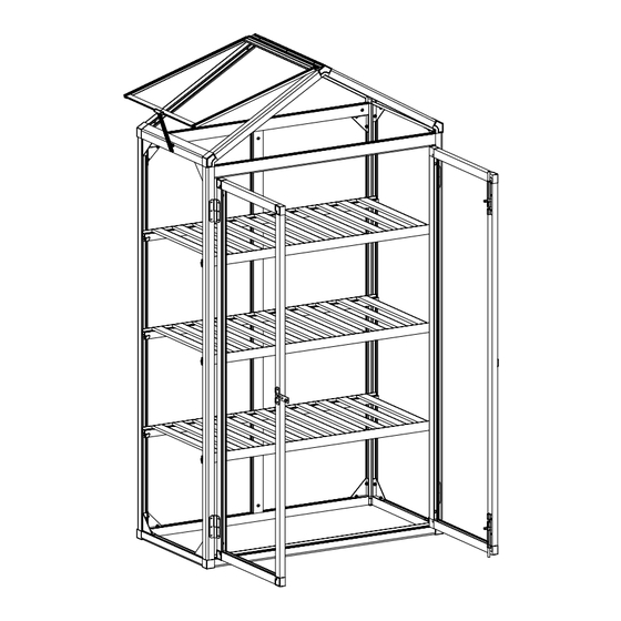
- Page 26 Put 12 x W01 on the hangers of L01A,L03A & B at the positions where you want to install the shelves. L10x11pcs Secure L10 onto L09 with screws.
- Page 27 3 shelves Put each shelf onto each W01.
Need help?
Do you have a question about the NURSERY GREENHOUSE and is the answer not in the manual?
Questions and answers