Table of Contents
Advertisement
Quick Links
Advertisement
Table of Contents
Troubleshooting

Related Manuals for Campbell HygroVUE 5


Summary of Contents for Campbell HygroVUE 5
- Page 1 Revision: 11/2022 2022 Copyright © 2019 – Campbell Scientific, Inc.
-
Page 2: Table Of Contents
Table of contents 1. Introduction 2. Precautions 3. Initial inspection 4. QuickStart 5. Overview 6. Specifications 6.1 Temperature measurement 6.2 Relative humidity measurement 7. Installation 7.1 Wiring to data logger 7.2 Data logger programming 7.3 CRBasic programming 7.4 Siting 7.4.1 Installation in a RAD06 radiation shield 7.4.2 Mount the shield 8. - Page 3 10. Attributions and references Appendix A. Importing Short Cut code into CRBasic Editor Appendix B. CRBasic example program Appendix C. Environmental performance C.1 Exposure to pollutants C.2 Operating range of the RH element C.3 Measurement below 0 °C Appendix D. SDI-12 sensor support D.1 SDI-12 command basics D.1.1 Acknowledge active command (a!) D.1.2 Send identification command (al!)
-
Page 4: Introduction
Relative Humidity and Temperature sensors. The HygroVUE sensors feature a low maintenance design with a highly stable and accurate replaceable RH chip that will lower the total cost of deployment throughout a network. The HygroVUE 5 uses the SDI-12 communications protocol to communicate with any SDI-12 recorder, simplifying wiring and programming. -
Page 5: Quickstart
Celsius. This can be changed by clicking the Deg C box and selecting Deg F, for degrees Fahrenheit, or K for Kelvin. SDI-12 Address defaults to 0. Enter the correct SDI-12 Address for the HygroVUE 5 if it has been changed from the factory-set default value. - Page 6 Data Output Storage Interval. Click Next. NOTE: Making measurements from the HygroVUE 5 more frequently than 5 seconds can result in small additional errors due to self-heating of the element. If the main scan rate needs to be faster than this, please read Sensor measurement (p.
- Page 7 7. Select the measurement and its associated output option. 8. Click Finish and save the program. Send the program just created to the data logger if the data logger is connected to the computer. 9. If the sensor is connected to the data logger, check the output of the sensor in the data display in LoggerNet, RTDAQ, or PC400 to make sure it is making reasonable measurements.
-
Page 8: Overview
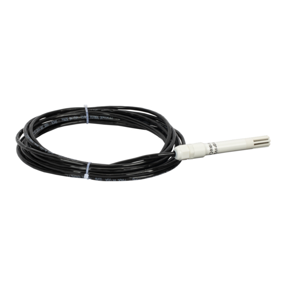
5. Overview The HygroVUE 5 sensor uses a single-chip element that incorporates both a temperature and an RH sensor. Each element is individually calibrated with the calibration corrections stored on the chip. The element is easily changed in the field, reducing downtime and calibration costs. -
Page 9: Temperature Measurement
Length: 115 mm (4.52 in) , sensor only, without cable Housing material: White PET-P Housing classification: IP67 (electronics housing) Sensor protection: Outer glass-filled polypropylene cap fitted with a stainless steel mesh dust filter with nominal pore size of <30 µm. The sensor element is fitted with a PTFE protective film with a filtration efficiency of >99.99% for particles of 200 nm or larger size. -
Page 10: Installation
Reported resolution: 0.001% RH Repeatability**: 0.05% RH Response time with filter: 8 s (63% response time in air moving at 1 m/s @ 25 °C) Environmental performance: See Environmental performance (p. 24) *The accuracy figures quoted are relative to factory standards. **Values are 3 standard deviations of 25 measurements at constant humidity. -
Page 11: Data Logger Programming
HygroVUE 5 is connected to C3 on a CR1000X, C4 cannot be used in the TimerInput(), PulseCount(), or WaitDigTrig() instructions. The SDI-12 address of the HygroVUE 5 can be set two ways: by sending the required commands to the sensors via an SDI-12 recorder/data logger that allows talk through to the sensor. -
Page 12: Siting
(p. 19) for a list of references that discuss temperature and relative humidity sensors. When used in the field, the HygroVUE 5 must be housed in a radiation shield. Typically, the RAD06 unventilated or the TS100SS fan-aspirated solar radiation shield is used. -
Page 13: Installation In A Rad06 Radiation Shield
The Apogee Instruments aspirated TS100SS shield can also be used where minimal solar errors and a fast speed of response is desired. A special adapter is available to allow the HygroVUE 5 to fit within the shield. Please refer for the documentation for that shield for further installation instructions. -
Page 14: Mount The Shield
Figure 7-1. HygroVUE 5 detail of insertion in a RAD06 shield 7.4.2 Mount the shield 1. Attach the radiation shield to the tripod mast, crossarm, or tower leg using the supplied U-bolt or band clamp. See Figure 7-2 (p. 12) for an example of shield mounting. -
Page 15: Operation
Figure 7-2. HygroVUE 5 installed in a RAD06 radiation shield on a pole 8. Operation 8.1 Sensor measurement 8.2 Measurements in programs with fast scan rates 8.3 Long cables 8.4 Power conservation 8.5 Measuring multiple SDI-12 sensors 8.1 Sensor measurement... - Page 16 For the HygroVUE 5 this instruction is rarely used because the instruction takes longer to execute than the M! or R! commands.
-
Page 17: Measurements In Programs With Fast Scan Rates
The HygroVUE 5 also supports the MC!, CC!, and RC! instructions, which are the same as the M!, C!, and R! instructions, but a cyclic redundancy check (CRC) is added that validates the data. Use of the checksum option is only normally necessary for long cable runs. -
Page 18: Power Conservation
In very low-power applications, battery power can be conserved by turning the 12 V supply to the HygroVUE 5 on just before the measurement (allowing a warm-up time of at least 1.8 s) and then turning it off afterwards. If available, the switched-12 V output of the data logger can be used. -
Page 19: Troubleshooting
Swap the element for another one. 9.2 Maintenance The HygroVUE 5 sensor requires minimal maintenance, but dust, debris, and salts on the filter cap will degrade sensor performance. Check the white filter on the end of the sensor for debris. If dirt or salt is ingrained in the filter, clean with distilled water or replace it. -
Page 20: Calibration
CAUTION: The HygroVUE 5 sensor body is sealed and filled with a potting compound to totally protect the electronics from any water ingress. This means there are no serviceable parts within the sensor body. - Page 21 CAUTION: If dirt, salt, or grease are left on the face of the sensor element during the process of handling the element, it may influence the measurements made. 2. Disconnect the sensor from the 12 V power supply. 3. Remove the filter cap by unscrewing it counter clockwise when looking towards the tip of the sensor.
-
Page 22: Attributions And References
6. With the element removed, check for dirt and corrosion around the socket. Use a damp cloth to remove dirt or salts that might be there. 7. Unpack the replacement element, avoiding static discharges to the element by making sure you touch the packaging before the element. - Page 23 EPA, 2008: Quality Assurance Handbook for Air Pollution Measurement Systems, Vol. IV, Meteorological Measurements, Ver. 2.0, EPA-454/B-08-002 (revised 2008). Office of Air Quality Planning and Standards, Research Triangle Park, NC 27711. Meyer, S. J. and K. G. Hubbard, 1992: Nonfederal Automated Weather Stations and Networks in the United States and Canada: A Preliminary Survey, Bulletin Am.
-
Page 24: Appendix A. Importing Short Cut Code Into Crbasic Editor
Appendix A. Importing Short Cut code into CRBasic Editor Short Cut creates a .DEF file that contains wiring information and a program file that can be imported into CRBasic Editor. By default, these files reside in the C:\campbellsci\SCWin folder. Import Short Cut program file and wiring information into CRBasic Editor: 1. -
Page 25: Appendix B. Crbasic Example Program
CR1000 data loggers. For a CR200(X)-series program, see an older manual at www.campbellsci.com/old-manuals CRBasic Example 1: CR1000X program measuring the HygroVUE 5 'Program measures one HygroVUE 5 sensor every 10 seconds and stores the 'average temperature and a sample of relative humidity every 10 minutes. 'Wiring Diagram... - Page 26 CRBasic Example 1: CR1000X program measuring the HygroVUE 5 Scan(10,Sec,1,0) 'HygroVUE 5 Temperature & Relative Humidity Sensor measurements 'AirTC' 'and 'RH' SDI12Recorder(TRHData(),C1,"0","M!",1,0) 'Call Data Tables and Store Data CallTable(TenMin) NextScan EndProg HygroVUE™5 Temperature and Relative Humidity Sensor...
-
Page 27: Appendix C. Environmental Performance
Appendix C. Environmental performance This appendix details tests and limitations of the sensor when exposed to extremes of the environment. C.1 Exposure to pollutants All capacitive sensors are susceptible to pollutants to some degree. The vapors may interfere with the polymer layers used in the structure of the sensing element. The diffusion of chemicals into the polymer may cause temporary or even permanent shifts in both offset and sensitivity. -
Page 28: Measurement Below 0 °C
World Meteorological Organization. If an RH value is required to be referenced to ice, the HygroVUE 5 readings will need to be corrected. Please refer to standard text points on this matter for the correction required. -
Page 29: Appendix D. Sdi-12 Sensor Support
Serial Data Interface at 1200 baud (SDI-12 ) is a protocol developed to simplify sensor and data logger compatibility. Only three wires are necessary—serial data, ground, and 12 V. With unique addresses, multiple SDI-12 sensors can connect to a single SDI-12 terminal on a Campbell Scientific data logger. -
Page 30: Acknowledge Active Command (A!)
Table D-1: Campbell Scientific sensor SDI-12 command and response sets Name Command Response Address query a<CR><LF> aAb! Change address b<CR><LF> Start measurement atttn<CR><LF> aM1!...aM9! Start measurement aMC! atttn <CR><LF> aMC1!...aMC9! and request CRC Start concurrent measurement atttnn<CR><LF> aC1!...aC9! aCC! Start concurrent measurement atttnn<CR><LF>... -
Page 31: Start Verification Command (Av!)
ll = SDI-12 version number (indicates compatibility) cccccccc = 8-character vendor identification vvv = 3 characters specifying the sensor version (operating system) xxx…xx = Up to 13 optional characters used for a serial number or other specific sensor information that is not relevant for operation of the data logger <CR><LF>... -
Page 32: Start Measurement Commands (Am!)
D.1.6 Start measurement commands (aM!) A measurement is initiated with the M! command. The response to each command has the form atttn<CR><LF>, where a = sensor address ttt = time, in seconds, until measurement data is available; when the data is ready, the sensor notifies the data logger, and the data logger begins issuing D commands. - Page 33 nn = the number of values to be returned when one or more subsequent D! commands are issued. See the following example. A data logger has three sensors wired into terminal C1. The sensors are addresses X, Y, and Z. The data logger will issue the following commands and receive the following responses: Table D-3: Example aC! sequence The data logger makes a request to sensor X to start...
-
Page 34: Start Measurement Commands With Cyclic Redundancy Check (Amc! And Acc!)
Table D-3: Example aC! sequence Ten seconds later, after a total of 40 seconds have passed, the data logger starts the process of YD0! collecting data from sensor Y by issuing the first D command. The sensor immediately responds with the sensor Y+1+2+3+4+5+6<CR><LF>... -
Page 35: Continuous Measurement Command (Ar0
Transparent mode is entered while the computer is communicating with the data logger through a terminal emulator program. It is accessed through Campbell Scientific data logger support software or other terminal emulator programs. Data logger keyboards and displays cannot be used. -
Page 36: Changing An Sdi-12 Address
SDI-12 sensor. The steps shown in Changing an SDI-12 address (p. 33) are used with most Campbell Scientific data loggers. D.3.1 Changing an SDI-12 address This example was done with a CR1000X, but the steps are only slightly different for Granite-series, CR6, CR800-series, CR300-series data loggers. - Page 37 6. Select All Caps Mode. 7. Press Enter until the data logger responds with the data logger (CR1000X>) prompt. 8. Type SDI12 and press Enter. 9. At the Select SDI12 Port prompt, type the number corresponding to the control port where the sensor is connected and press Enter.
- Page 38 11. To change the SDI-12 address, type aAb!, where a is the current address from the previous step and b is the new address. Press Enter. The sensor changes its address and responds with the new address. In the following example, the sensor address is changed from 0 to B. 12.
-
Page 39: Appendix E. Sensor Element Calibration
The sensor elements are individually calibrated during manufacture. The manufacturer publishes a statement (see Figure E-1 [p. 36]) as a description of and evidence of traceability of the calibration of the HygroVUE 5 sensor element. Figure E-1. Calibration certificate HygroVUE™5 Temperature and Relative Humidity Sensor... - Page 40 See Product Details on the Ordering Information pages at www.campbellsci.com . Other manufacturer's products, that are resold by Campbell Scientific, are warranted only to the limits extended by the original manufacturer. Refer to www.campbellsci.com/terms#warranty for more information.
- Page 41 To obtain a Returned Materials Authorization or Repair Reference number, contact your CAMPBELL SCIENTIFIC regional office. Please write the issued number clearly on the outside of the shipping container and ship as directed. For all returns, the customer must provide a “Statement of Product Cleanliness and Decontamination”...
- Page 42 Do not recharge, disassemble, heat above 100 °C (212 °F), solder directly to the cell, incinerate, or expose contents to water. Dispose of spent batteries properly. WHILE EVERY ATTEMPT IS MADE TO EMBODY THE HIGHEST DEGREE OF SAFETY IN ALL CAMPBELL SCIENTIFIC PRODUCTS, THE CUSTOMER ASSUMES ALL RISK FROM ANY INJURY RESULTING FROM IMPROPER INSTALLATION, USE, OR MAINTENANCE OF TRIPODS, TOWERS, OR...
- Page 43 Campbell Scientific Regional Offices Australia France Thailand Location: Garbutt, QLD Australia Location: Vincennes, France Location: Bangkok, Thailand Phone: 61.7.4401.7700 Phone: 0033.0.1.56.45.15.20 Phone: 66.2.719.3399 Email: info@campbellsci.com.au Email: info@campbellsci.fr Email: info@campbellsci.asia Website: www.campbellsci.com.au Website: www.campbellsci.fr Website: www.campbellsci.asia Brazil Germany Location: São Paulo, SP Brazil...
Need help?
Do you have a question about the HygroVUE 5 and is the answer not in the manual?
Questions and answers