Table of Contents
Advertisement
Quick Links
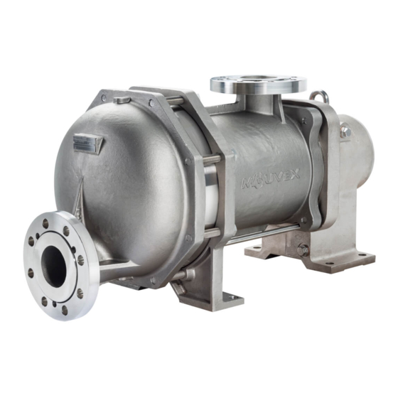
SLC12 i - SLC12 i HT
SLC18 i - SLC18 i HT
SL Series pumps are covered 24 months by warranty within the limits mentioned in our General Sales Conditions.
In case of a use other than that mentioned in the Instructions manual, and without preliminary agreement of MOUVEX,
warranty will be canceled.
Z.I. La Plaine des Isles - F 89000 AUXERRE - FRANCE
Tel. : +33 (0)3.86.49.86.30 - Fax : +33 (0)3.86.49.87.17
contact@mouvex.com - www.mouvex.com
PUMPS
WARRANTY :
INSTRUCTIONS 1004-C00 e
Section
1004
Effective
March 2018
Replaces
October 2016
Original instructions
INSTALLATION
OPERATION
MAINTENANCE
Your distributor :
Advertisement
Table of Contents

Subscribe to Our Youtube Channel
Related Manuals for PSG Dover Mouvex SLC12 i


Summary of Contents for PSG Dover Mouvex SLC12 i
- Page 1 INSTRUCTIONS 1004-C00 e Section 1004 Effective March 2018 Replaces October 2016 Original instructions SLC12 i - SLC12 i HT SLC18 i - SLC18 i HT PUMPS INSTALLATION OPERATION MAINTENANCE WARRANTY : SL Series pumps are covered 24 months by warranty within the limits mentioned in our General Sales Conditions. In case of a use other than that mentioned in the Instructions manual, and without preliminary agreement of MOUVEX, warranty will be canceled.
-
Page 2: Table Of Contents
ECCENTRIC PISTON PUMP MOUVEX PRINCIPLE SAFETY INSTRUCTIONS, STORAGE, INSTALLATION AND MAINTENANCE SLC12 i - SLC12 i HT - SLC18 i - SLC18 i HT MODELS USED PRESSURE UNITS Unit without suffix : TECHNICAL CHARACTERISTICS Differential pressure, for example, pressure difference between equipment suction and discharge. -
Page 3: Overall Dimensions
1. OVERALL DIMENSIONS NT 1004-C00 03 18 SLC12 i - SLC18 i - SLC12 i HT - SLC18 i HT e 3/28... - Page 4 1. OVERALL DIMENSIONS (continued) NT 1004-C00 03 18 SLC12 i - SLC18 i - SLC12 i HT - SLC18 i HT e 4/28...
- Page 5 1. OVERALL DIMENSIONS (continued) NT 1004-C00 03 18 SLC12 i - SLC18 i - SLC12 i HT - SLC18 i HT e 5/28...
- Page 6 1. OVERALL DIMENSIONS (continued) NT 1004-C00 03 18 SLC12 i - SLC18 i - SLC12 i HT - SLC18 i HT e 6/28...
- Page 7 1. OVERALL DIMENSIONS (continued) NT 1004-C00 03 18 SLC12 i - SLC18 i - SLC12 i HT - SLC18 i HT e 7/28...
- Page 8 1. OVERALL DIMENSIONS (continued) NT 1004-C00 03 18 SLC12 i - SLC18 i - SLC12 i HT - SLC18 i HT e 8/28...
-
Page 9: Installation
2. INSTALLATION POSSIBLE POSITIONS Pumps with heating jacket : see § OVERALL DIMENSIONS - Heating jacket SUCTION (standard inlet manifold) 2 STANDARD (1) SUCTION (turn able inlet manifold) 2 STANDARD DISCHARGE 4 STANDARD (1) ONLY POSITION FOR THE JACKETS 2.1 Installation design Suction pipe diameter Diameter must be at least equal to pump port diameter 2.1.1 Pump... -
Page 10: Orientation Of The Pump Ports
2. INSTALLATION (continued) • If pumped liquid presents a risk of in pipe solidification and potential dilatation, low points on the pipe should be avoided or equipped with drain valve. R = 3 x D minimum L = 10 x D minimum •... -
Page 11: Protection Of The Pump Installation
2. INSTALLATION (continued) 2.4 Protection of the pump installation WARNING • Before any start-up, during operation or complete stop- ping of the pump, make sure the valves are open. PUMPS OPERATING AGAINST A CLOSED • During stop periods, with the pump full of product, VALVE CAN CAUSE SYSTEM FAILURE, PERSONAL INJURY AND PROPERTY either the suction or discharge circuit must be left open... -
Page 12: Hoisting Devices
2. INSTALLATION (continued) 2.5 Hoisting devices 2.6 Unit Assembly Hoisting points : The following instructions apply to pumps delivered with a bare shaft or for MOUVEX motor-driven pump units (if the latter have no specific instruction notice). 2.6.1 INSTALLATION OF UNITS WARNING BE CAREFUL WITH THE WEIGHT OF THE PARTS... - Page 13 2. INSTALLATION (continued) 2.6.2 ALIGNMENT OF THE MOTOR/PUMP OR Controlling the alignment at each stage of the installa- tion is important to be sure that none of these stages REDUCTION GEAR/PUMP SHAFTS have generated stresses on the unit or the pump : WARNING •...
-
Page 14: Utilisation
2. INSTALLATION (suite) 2.6.5 CONTROL OF THE SENSE OF ROTATION WARNING WARNING IF OPERATED WITHOUT THE SHAFT GUARD, THERE IS CONSIDERABLE RISK OF SEVERE PERSONAL INJURY, SIGNIFI- CANT PROPERTY DAMAGE OR EVEN TAKE ALL NECESSARY MEASURES TO DEATH. RENDER ANY START-UP, EVEN ACCI- Do not operate DENTAL, OF THE PUMP DURING THE without guard... -
Page 15: Clean In Place (Cip) & Sterilisation In Place (Sip)
4. CLEAN IN PLACE (CIP) & STERILISATION IN PLACE (SIP) 4.1 General 4.3 Pumps arranged in series On-site cleaning (CIP) of an installation is undertaken by This type of assembly is preferred in all cases. It ensures circulating various cleaning solutions through the equip- optimal cleaning for the pump and makes use of the spe- ment parts. -
Page 16: Pumps Arranged In Parallel
4. CLEAN IN PLACE (CIP) & STERILISATION IN PLACE (SIP) (continued) 4.4 Pumps arranged in parallel For applications where cleaning is easy and the differen- Max pressure tial pressure of, the SL Series pump is lower than 2 bar 3 barg (43,5 psig) (29 psi) during this operation, assembly in parallel is authorised. -
Page 17: Successive Cycles
4. CLEAN IN PLACE (CIP) & STERILISATION IN PLACE (SIP) (continued) 4.5 Successive cycles 4.6 Sterilisation In Place (SIP) Generally, the most efficient CIPs comprise 5 stages : The serie SL pumps are perfectly adapted to all pro- 1. Pre-washing with clean water cesses using SIP (Sterilisation In Place) : pump stopped Water at room temperature. -
Page 18: Opening Of The Pump
6. OPENING OF THE PUMP WARNING WARNING DISCONNECTING THE FLUID OR PRES- TAKE ALL NECESSARY MEASURES TO SURE CONTAINMENT COMPONENTS RENDER ANY START-UP, EVEN ACCI- DURING PUMP OPERATION CAN CAUSE DENTAL, OF THE PUMP DURING THE SERIOUS PERSONAL INJURY, DEATH OR WORK IMPOSSIBLE. -
Page 19: Checking Of Parts
6. OPENING OF THE PUMP (continued) • With the help of a hub puller, extract the piston 301. When controlling the piston and even if it has not reached its minimum dimensions, it may show following aspects, especially on abrasive liquid pumping or low viscosity : •... -
Page 20: Assembly Of Cylinder/Piston
7. ASSEMBLY OF CYLINDER/PISTON • Check the state of the seals 205, 305, 306, 113 and • Hold the piston 301 with a 70 Open-end spanner or a mon- replace them if necessary. key wrench and screw-up the nut 304 after mounting the seal 305 on to the rear face. -
Page 21: Protection Of The Bellows
8. PROTECTION OF THE BELLOWS PUMP WITH BELLOWS MONITORING SYSTEM BY WARNING ATEX PRESSURE SWITCH DO NOT HIT THE PRESSURE SWITCH AND THE CONNECTIONS. BE CAREFUL WITH THE WEIGHT OF THE DO NOT REMOVE THE PRESSURE SWITCH. PARTS WHEN THEY ARE BEING REMOVED. DO NOT UNCOUPLE THE HOSE BETWEEN PRESSURE The weight ot the parts SWITCH AND BEARING. -
Page 22: Changing The Lip Seal
8. PROTECTION OF THE BELLOWS (continued) The spare transmissions delivered are equipped with a tubular foam protection. We advise leaving this protection around the bellows until remounting of the piston and cylinder. DO NOT FORGET TO REMOVE THE PROTECTION BEFORE MOUNTING THE CYLINDER. -
Page 23: Changing The Orientation Of The Ports
10. CHANGING THE ORIENTATION OF THE PORTS 10.3 Flanges dismantling WARNING • Remove the three screws 136. BE CAREFUL WITH THE WEIGHT OF THE PARTS WHEN THEY ARE BEING REMOVED. The weight ot the parts can be dangerous and may provoke bodily injuries or material damages. -
Page 24: Draining Of Bearing
11. DRAINING OF BEARING CAUTION CAUTION THE SURFACES OF THE PUMP AND THE PUMP LUBRICANT IS VERY SLIPPERY OIL TRANSMISSION CAN BE AT A AND MAY CAUSE SERIOUS INJURY. ANY TEMPERATURE LIABLE TO CAUSE SPILLS MUST BE CLEANED UP. INJURY OR SEVERE DAMAGE. Slippery lubricant. -
Page 25: Options
12. OPTIONS 12.1 Bellows monitoring system See Instructions 1011-S00. 13. STORAGE 13.3 Restarting If necessary, refer to § MAINTENANCE for pump disassembly. Follow the standard start-up procedure for the pump/ 13.1 Short duration (≤ 1 month) motor-driven pump, as well as the instructions below. Turn the pump by hand to make sure the parts move WARNING freely. -
Page 26: Troubleshooting
14. TROUBLESHOOTING ZERO OR INSUFFICIENT FLOW PRELIMINARY CHECKS Make sure that the plastic plugs have been taken away from the ports of the pump and that the pump is running (defective drive, damaged motor, etc., faulty transmission : broken coupling, sliding belt, worn or poorly coupled clutch, etc.). - Page 27 14. TROUBLESHOOTING (continued) ABNORMAL HEATING OF BEARINGS This heating can be caused by : - excessive tension in the transmission (belt or chain) on the pump shaft. - excessive pulling on the pump flanges by the piping (in this case, it must have been necessary to force the piping into position to connect it to the pump).
-
Page 28: Certificate Of Conformity
15. CERTIFICATE OF CONFORMITY NT 1004-C00 03 18 SLC12 i - SLC18 i - SLC12 i HT - SLC18 i HT e 28/28...
Need help?
Do you have a question about the Mouvex SLC12 i and is the answer not in the manual?
Questions and answers