Table of Contents
Advertisement
Advertisement
Table of Contents

Related Manuals for Pulsar PG5250BCO


Summary of Contents for Pulsar PG5250BCO
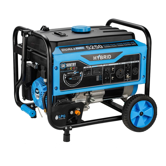
- Page 1 Model No.: PG5250BCO Generator OPERATOR’S MANUAL support@pulsar-products.com...
-
Page 2: Table Of Contents
TABLE OF CONTENTS Introduction..............................3 Parts Ordering / Customer Service....................... 3 Product Specifications........................3 Safety Rules ..............................4 Safety Symbols..........................4 Safety Instructions ..........................4 Features ............................... 7 Assembly ..............................9 Unpacking ..............................9 Packing List ............................9 Attaching Wheels .......................... -
Page 3: Introduction
INTRODUCTION Thank you for purchasing this superior quality portable generator from Pulsar P roducts Inc. When operating and maintaining this product as instructed in this manual, your generator will give you many years of reliable service. Product Specifications: This generator is an engine-driven, revolving field, alternating current (AC) portable generator. It is designed to supply electrical power to operate tools, appliances, camping equipment, lighting, or serve as a backup power source during power outages. -
Page 4: Safety Rules
SAFETY RULES Safety Symbols Indicates a potentially hazardous situation which could result in serious injury or death if not WARNING! avoided. Indicates a potentially hazardous situation which could result in damage to equipment or CAUTION! property. Toxic Fumes Risk of fire Risk of explosion Risk of electric shock Hot surface... - Page 5 SAFETY RULES Never exceed generator’s wattage / amperage capacity. This could damage the generator WARNING! and / or connected electrical devices. Check operating voltage and frequency of all electrical devices prior to plugging in to generator. • Never start or stop engine with electrical devices plugged in to the receptacles. Failure to do WARNING! so could damage the generator and / or connected electrical devices.
- Page 6 Never transport or make adjust this unit while it is running. • Never insert objects through cooling slots. Never operate this unit if there are any broken or missing parts and only use Pulsar WARNING! replacement parts specifically designed for this unit.
-
Page 7: Features
FEATURES A - ON/OFF Switch Two 120 V GFCI Outlets (NEMA 5-20R) B - Status Display H - TT-30 RV Outlet I - Voltage Selector C - Circuit Breakers J - Ground Terminal D - Main Circuit Breaker K - 120/240 Volt AC, 30 Amp Twist-Lock Outlet (NEMA L14-30) E - Fuel Selector Switch F - CO Sensor Light... - Page 8 FEATURES L - Tank Vapor Valve R - Support Foot M - Fuel Gauge S - Fuel Cap N - Choke Lever T - Fuel Tank O - Air Filter Housing U - Fuel Valve P - Pull Start V - CO sensor Q - Handle W - Oil Fill (Dipstick) X - Propane Inlet...
-
Page 9: Assembly
ASSEMBLY Unpacking 1. Place box on a level surface. 2. Remove all items from box except the generator. Make sure all items listed on the packing list are included and undamaged 3. Cut-down the sides of the box being careful to avoid touching the generator. 4. -
Page 10: Attaching Wheels
ASSEMBLY Attaching Wheels (See fig 1) • Parts needed - 2 wheels, 2 axles, 2 washers and 2 hair pins. • Raise or tilt generator so you can slide the wheel axle pin into the wheel, the washer, and the wheel mounting hole located on the side of the frame. -
Page 11: Adding Oil/Checking Engine Oil
ASSEMBLY Handle Assembly (See fig 3) 1. Install handle lock holder by inserting bolt and lock nut. (fig 3) 2. Install handle bracket to frame with 2 bolts and lock nuts as shown on illustration. 3. Set handle in the bracket aligning the holes and insert handle bolt and lock nut. Fig 3 Adding / Checking Engine Oil (See fig 4) •... -
Page 12: Adding Fuel
ASSEMBLY Adding Fuel (See fig 5) • Set generator outdoors in a well-ventilated area, away from structures and people. • Slowly remove fuel cap. • Insert a funnel into the fuel tank and carefully pour gasoline into the tank until fuel level reaches 1 ½ inches below the top of the neck. -
Page 13: Operation
OPERATION Grounding the Generator (See fig 7) The portable generator is equipped with a terminal for the connection of a ground electrode conductor where a grounding electrode system is required by NEC Article 250.34(A). The equipment grounding conductor terminals of the generator receptacles are bonded to the generator frame. - Page 14 OPERATION PROPANE Fig 9 Fig 8 Fig 10 WAIT 5sec CHOKE CHOKE CHOKE LEVER CHOKE LEVER Fig 11 Fig 12 Recoil Start Fig 13 SKIP THIS IF THE ENGINE IS WARM OR HOT.
-
Page 15: How To Stop Engine
OPERATION Never start or stop engine with electrical devices plugged in to the receptacles. Failure to WARNING! heed this warning could damage the generator and / or connected electrical devices. • Always start the engine and let it stabilize before connecting any electrical devices. •... -
Page 16: Don't Overload Generator
OPERATION 120 / 240 Volt AC, 30 Amp locking receptacle • This receptacle has a 30 Amp push-to reset circuit breaker to protect against overload. • This receptacle is rated to operate 120 Volt, AC, single phase, 60Hz loads requiring up to 3600 watts (3.6 kW) at 30 Amps. -
Page 17: Wattage Reference Guide
OPERATION Operating voltage and frequency requirement of all electrical equipment should be checked prior to plugging them into this generator. Damage may result if the equipment is not designed to operate within a +/- 10% voltage variation, and +/- 3 Hz frequency variation from the generator name plate ratings. -
Page 18: Cold Weather Operation
OPERATION Status Display (See Fig 18) Use this meter along with the manual to determine when and what type of service on the unit is needed. The display will show the word “P25” at the first 25 hours of operation and again at every 100 hours of operation after. Power Management Start engine without anything connected to generator. -
Page 19: Maintenance
MAINTENANCE Regular maintenance will extend the life of this generator and improve its performance. The warranty does not cover damage resulting from operator negligence, misuse, or abuse. To receive full value from the warranty, operator must maintain the generator as instructed in this manual, including proper storage. Before inspecting or servicing this machine, make sure the engine is off and no parts are WARNING! moving. -
Page 20: Changing Oil
MAINTENANCE Changing Oil (See Fig 19) • Run the Generator until the Engine is warm, then shut OFF. • Place generator on a level surface. • Remove the crankcase dipstick. • Place an oil pan underneath the oil drain hole to collect used oil. Oil Fill &... -
Page 21: Engine Maintenance
Spark Arrestor (See Fig 22) • Inspect the spark arrestor for breaks or holes. replace if necessary. To purchase a replacement spark arrestor contact PULSAR customer service. • Use a brush to remove carbon deposits from the spark arrestor screen as needed. -
Page 22: Maintaining Fuel Valve
MAINTENANCE High Altitude Operation At higher altitudes, the standard carburetor air/fuel mixture will be too rich. Performance will decrease, and fuel consumption will increase. A very rich mixture will also foul the spark plug and cause hard starting. Operation at an altitude that differs from that at which this engine was certified, for extended periods of time, may increase emissions. -
Page 23: How To Store
MAINTENANCE • If needed, install a fuel hose that will extend to a suitable fuel container large enough to catch the fuel being drained from the tank. • Turn the fuel valve to the ON position and open the fuel tank cap slightly to equalize pressure. •... -
Page 24: Troubleshooting
TROUBLESHOOTING Problem Cause Solution Engine is running, but AC output is not 1. Open circuit breaker 1. Reset circuit breaker available 2. Poor connection 2. Check and repair 3. Defective cord set 3. Check and repair 4. Connected device is faulty 4. - Page 25 The YELLOW light will flash for at least five minutes after a fault. The generator can be re-started, but may continue to shutoff. A CO sensor fault can only be diagnosed and repaired by an authorized Pulsar service center.
-
Page 26: Diagrams
DIAGRAMS...
Need help?
Do you have a question about the PG5250BCO and is the answer not in the manual?
Questions and answers