Sign In
Upload
Download
Table of Contents
Contents
Add to my manuals
Delete from my manuals
Share
URL of this page:
HTML Link:
Bookmark this page
Add
Manual will be automatically added to "My Manuals"
Print this page
×
Bookmark added
×
Added to my manuals
Manuals
Brands
AC Infinity Manuals
Controller
CONTROLLER 79
Manual
AC Infinity CONTROLLER 79 Manual
Hide thumbs
1
2
3
4
Table Of Contents
5
6
7
8
9
10
11
12
13
14
15
16
17
18
19
20
21
22
23
24
25
26
27
28
29
30
31
32
33
34
35
36
37
38
39
40
41
42
43
44
page
of
44
Go
/
44
Contents
Table of Contents
Bookmarks
Table of Contents
Table of Contents
Manual Index
Product Warning
Interference from MH and HPS Lights
Key Features
Product Contents
Powering and Setup
Programming
Other Settings
Download the App
Add a Device
Faq
Other AC Infinity Products
Warranty
Advertisement
Quick Links
1
Key Features
2
Powering and Setup
3
Programming
4
Download the App
Download this manual
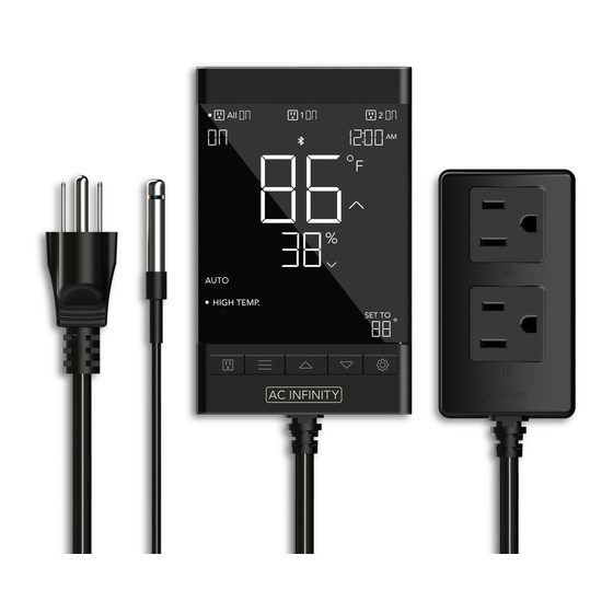
SMART OUTLET
ENVIRONMENTALLY CONTROLLED
USER MANUAL
Table of
Contents
Previous
Page
Next
Page
1
2
3
4
5
Advertisement
Table of Contents
Need help?
Do you have a question about the CONTROLLER 79 and is the answer not in the manual?
Ask a question
Questions and answers
Related Manuals for AC Infinity CONTROLLER 79
Controller AC Infinity CONTROLLER 75 Manual
(44 pages)
Controller AC Infinity CONTROLLER 67 User Manual
(31 pages)
Controller AC Infinity CONTROLLER 63 User Manual
(12 pages)
Controller AC Infinity CONTROLLER 69 User Manual
(56 pages)
Controller AC Infinity CONTROLLER 69 User Manual
(44 pages)
Controller AC Infinity CONTROLLER 69 PRO User Manual
(60 pages)
Controller AC Infinity AC-CTC7 User Manual
Co2 controller environmental monitor (32 pages)
Controller AC Infinity SMART OUTLET User Manual
(44 pages)
Controller AC Infinity THERMAL TRIGGER User Manual
For airplate and multifan series (12 pages)
Controller AC Infinity AC-CRA5 User Manual
Co2 regulator (20 pages)
Controller AC Infinity CTR69X User Manual
Controller 69 wifi (47 pages)
This manual is also suitable for:
Controller 75
Ctr79a
Ctr75a
Table of Contents
Print
Rename the bookmark
Delete bookmark?
Delete from my manuals?
Login
Sign In
OR
Sign in with Facebook
Sign in with Google
Upload manual
Upload from disk
Upload from URL


Need help?
Do you have a question about the CONTROLLER 79 and is the answer not in the manual?
Questions and answers