Table of Contents
Advertisement
Advertisement
Table of Contents

Subscribe to Our Youtube Channel
Related Manuals for AC Infinity CONTROLLER 69


Summary of Contents for AC Infinity CONTROLLER 69
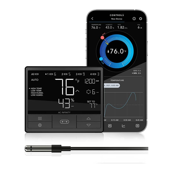
- Page 1 CONTROLLER 69 USER MANUAL USER MANUAL...
- Page 3 WELCOME Thank you for choosing AC Infinity. We are committed to product quality and friendly customer service. If you have any questions or suggestions, please don’t hesitate to contact us. Visit www.acinfinity.com and click contact for our contact information. EMAIL LOCATION support@acinfinity.com...
-
Page 4: Compatibility
819137022652 FAN COMPATIBILITY This controller is natively compatible with AC Infinity devices with UIS™ connectors. Older model inline fans with EC motors may be used with this controller using a Molex adapter. An EC-motor fan will have two cords coming out of its motor box for the power and the controller. Note that certain models that previously used DC-motors now contain EC-motors in updated builds. -
Page 5: Table Of Contents
................. Page 16 Other Settings ................Page 31 Download the App ................. Page 32 Add a Device ................. Page 33 Programming................Page 36 Settings................... Page 47 FAQ....................Page 49 Other AC Infinity Products ............. Page 50 Warranty ..................Page 51... -
Page 6: Key Features
SMART CONTROLLER VERSATILE PLACEMENT Bluetooth-enabled to connect Features automation controls Mount the controller on a steel with the AC Infinity app for that activate your devices surface using the rear magnet or access to smart automations, based on climate conditions, open the kickstand to sit it tilted climate data, and history logs. -
Page 7: Product Contents
PRODUCT CONTENTS SMART SENSOR UIS M - 4PIN F CONTROLLER PROBE ADAPTER (x1) (x1) (x2) WOOD SCREWS WOOD SCREWS WIRE (WALL MOUNT) (WALL HANG) (x2) (x2) (x1) -
Page 8: Powering And Setup
POWERING AND SETUP STEP 1 Plug your device’s UIS connector into one of the controller's ports. STEP 2 Plug the sensor probe into the controller’s 3.5mm jack. Set the probe near your plants in your grow tent for the most accurate reading. - Page 9 POWERING AND SETUP STEP 3 Plug your device’s power cord into an AC power outlet to power it and the controller. STEP 4 You may use the included tie mounts, wood screws, and zip ties to cable manage the cords. Secure the tie mounts onto a surface using the wood screws.
-
Page 10: Controller Mounting
CONTROLLER MOUNTING STEP 1 Locate a spot free of obstruction and secure the anchors into your wall. Twist the wood screws into the anchors. STEP 2(a) Hang the controller by the screws using the holes on the backside. You may also mount the controller using the magnet located behind the label. - Page 11 CONTROLLER MOUNTING STEP 2(b) Cords may be routed into or outside of the kickstand grooves, and through a cut hole behind the controller. KICKSTANDING Open the stand behind the controller to set it tilted on your desktop.
-
Page 12: Adding More Devices
ADDING MORE DEVICES The CONTROLLER 69 is built with four ports that enable you to power and control multiple fans at the same time. See image below for a sample configuration. Multi-Fan Connection CLOUDLINE 4" CLOUDLINE 6" EXPANSION DONGLE The expansion dongle will allow you to connect 2 or 4 devices with a single port and can support additional dongles to create more expansion ports (up to 64 units supported with the use of 20 dongles*). - Page 13 ADDING MORE DEVICES The CONTROLLER 69 is built with four ports that enable you to power and control multiple grow lights at the same time. See image below for a sample configuration. Multi-Light Connection EXPANSION DONGLE The expansion dongle will allow you to connect 2 or 4 devices with a single port and can support additional dongles to create more expansion ports (up to 64 units supported with the use of 20 dongles*).
-
Page 14: Universal Infinity System
Create independent timers and schedules for customized activation in your desired timeframe. Your grow system can be regulated using your controller hub or remotely on the AC Infinity app (paired with compatible controllers), where you will have access to automation programming and climate data. -
Page 15: Uis Compatibility
The expansion dongle will allow you to connect 2 or 4 devices with a single port and can support additional dongles to create more expansion ports (up to 64 units supported with the use of 20 dongles*). Intended for exclusive use with AC Infinity controllers built with UIS ports. UIS M - M... -
Page 16: Programming
PROGRAMMING 2. MODE BUTTON 1. PORT BUTTON 3. SETTING BUTTON Cycles through the controller’s modes: Cycles through up to four Cycles through the controller’s OFF, ON, AUTO (4 triggers), TIMER to connected devices. Each device settings: DISPLAY, CLOCK, ON, TIMER to OFF, CYCLE (ON and is programmed independently, or °F/°C, CALIB. - Page 17 PROGRAMMING PORTS Pressing the port button will cycle through the controller’s available ports: ALL, 1, 2, 3, and 4. Dot indicates the current device. No digit is displayed if a device is not plugged into the corresponding port. ALL PORTS Navigate to the ALL port to set simultaneous programming for all connected devices.
- Page 18 PROGRAMMING CONTROLLER MODES Pressing the mode button will cycle through the controller’s available programming modes: OFF, ON, AUTO (4 triggers), TIMER TO ON, TIMER TO OFF, CYCLE (On and Off), and SCHEDULE (On and Off). OFF MODE Your devices will not run while in this mode. The levle set while in this mode establishes the minimum level in other modes.
- Page 19 PROGRAMMING AUTO MODE (HIGH TEMPERATURE TRIGGER) Pressing the up or down button sets the high temperature trigger. The devices will activate if the probe’s reading meets or exceeds this threshold. Once triggered, the devices will gradually ramp up to the level set in ON mode. If the probe’s reading falls below this trigger point, the devices will gradually slow down to a stop or at the level set in OFF mode.
- Page 20 PROGRAMMING AUTO MODE (HIGH HUMIDITY TRIGGER) Pressing the up or down button sets the high humidity trigger. The devices will activate if the probe’s reading meets or exceeds this threshold. Once triggered, the devices will gradually ramp up to the level set in ON mode. If the probe’s reading falls below this trigger point, the devices will gradually slow down to a stop or at the level set in Note that this trigger can activate as long...
- Page 21 PROGRAMMING TIMER TO ON MODE Pressing the up or down button sets a countdown time. Once the timer ends, the devices will trigger to run at the level set in ON Mode. If there is a level set in OFF Mode, the devices will run at that level during the countdown.
- Page 22 PROGRAMMING CYCLE MODE (ON AND OFF) Set an on duration and an off duration for the devices to cycle through continuously. Press the up or down button to first set a duration for the devices to activate. Then press the mode button again and set a duration for the devices to deactivate.
- Page 23 PROGRAMMING SCHEDULE MODE (ON AND OFF) Sets an on clock-time and an off clock-time schedule for the devices to follow daily. Press the up or down button to first set up an on clock-time to trigger ON mode, then press the mode button to set an off clock-time to trigger OFF mode.
- Page 24 PROGRAMMING CONTROLLER SETTINGS Pressing the setting button will cycle through the controller’s available settings: DISPLAY, °F/ °C, CLOCK, CALIB. T°, CALIB. H%, TRANS. T°, and TRANS. H%. DISPLAY SETTING Adjusts the display brightness and auto-dimming. Press the up or down button to cycle through levels 1, 2, 3, A2 and A3;...
- Page 25 PROGRAMMING °F/°C SETTING Changes the displayed units to Fahrenheit or Celsius. Press the up or down button to cycle through F and C. All displayed units will automatically convert when adjusting this setting. CLOCK SETTING Adjusts the current clock time. Press the up or down button to increase or decrease the time.
- Page 26 PROGRAMMING CALIBRATION TEMPERATURE SETTING Adjusts the temperature reading the sensor probe is measuring. Press the up or down button to increase or decrease the data figure in 2°F (or 1°C) increments. The calibration cycle ranges from -20°F to 20°F (or -10°C to 10°C) and will be applied to the sensor probe’s measurements.
- Page 27 PROGRAMMING TRANSITION TEMPERATURE SETTING Adjusts the transition threshold between the levels in the AUTO Mode temperature triggers. Press the up or down button to cycle through 0°F to 8°F (0°C to 4°C) and set a transition threshold. The level will be set one level above the OFF Mode level when the sensor temperature first meets or exceeds the high temperature trigger.
- Page 28 PROGRAMMING TRANSITION HUMIDITY SETTING Adjusts the transition threshold between the levels in the AUTO Mode humidity triggers. Press the up or down button to cycle through 0% to 8% to set a transition threshold. The level will be set one level above the OFF Mode level when the sensor humidity first meets or exceeds the high humidity trigger.
- Page 29 PROGRAMMING ALERT ICONS The alert icons are displayed at the top of the screen. Icons may flash when the controller signals an alert to notify you of any triggered function or alarm. ADVANCE PROGRAMMING Displays when an advance program set in the app is active. "ADV." will appear and override the controller if an automation program is in use.
- Page 30 PROGRAMMING BLUETOOTH Appears when the physical controller is connected to the app via Bluetooth. DISPLAY LOCK ALERT Displays when you lock the controller. The icon will flash and beep if you attempt to adjust the controller while it is still locked. TEMPERATURE/ HUMIDITY ALARM Flashes and beeps with alarm if the temperature/ humdity meet the trigger point set in the app.
-
Page 31: Other Settings
OTHER SETTINGS FACTORY RESET Holding the mode, up, and down buttons together for 5 sec- HOLD + onds will reset your controller and restore factory settings. This clears all user parameters in each controller mode and setting. CONTROLLER LOCK Holding the setting button will lock the controller in your cur- rent mode. -
Page 32: Download The App
DOWNLOAD THE APP THE AC INFINITY APP The AC Infinity app enables you to connect with the next generation of our intelligent controllers, giving you access to advance programs and environmental data. Download the AC Infinity app from the App Open the AC Infinity app. -
Page 33: Add A Device
ADD A DEVICE Connect the devices and probe into your Launch the app. Tap the (+) button, then controller. Plug the devices into a wall outlet. "SMART CONTROLLERS" Please note: Bluetooth must be enabled on your mobile device before starting the pairing process. - Page 34 ADD A DEVICE Hold the port button for 5 seconds to activate Select CONTROLLER 69 to begin pairing. Bluetooth. Wait for the Bluetooth icon to start flashing on your controller’s screen.
- Page 35 ADD A DEVICE Tap DONE button to complete the pairing Your controller will appear in your smart device process. with a unique ID. E-E000E DONE Please note: When pairing the app around multiple controllers, move your mobile device closer to your desired controller.
-
Page 36: App Programming
APP PROGRAMMING DEVICE PAGE Your controller will appear in your device page. Use the MASTER CONTROL toggle button to switch between the ALL port and the individual numbered ports. Your devices will share the same programming when navigating to the ALL port, or have independent programming when switching to the numbered ports. - Page 37 APP PROGRAMMING 1. MODE BUTTON 2. TEMPERATURE/HUMIDITY 3. SETTINGS Dropdown displays all available Toggles between current tempera- Adjusts app settings including controller modes: OFF, ON, AUTO, ture and humidity readings. Device Name, Temperature Display, TIMER TO ON, TIMER TO OFF, Device Brightness, Transitions, and CYCLE, and SCHEDULE.
- Page 38 APP PROGRAMMING CONTROLS TAB Contains all controller modes including the OFF, ON, AUTO, TIMER TO ON, TIMER TO OFF, CYCLE and SCHEDULE modes. Tap the paired device to enter the Controls tab, Tap the menu button to access the controller where you can adjust the controller modes.
- Page 39 APP PROGRAMMING CONTROLS TAB The control wheel displays the temperature/humidity, current settings, and time. Use the wheel hands, (+/-) stepper, or sliders Use the toggle switch to activate or deactivate to set your parameters. any climate triggers.
- Page 40 APP PROGRAMMING ADVANCE PROGRAMMING Creates automated activations, alarms, and push notifications. The adjustable modes in each program include those listed in controls tab. Once an advance program completes its programming (i.e. scheduling), the app will no longer override the controller's onboard settings.
- Page 41 APP PROGRAMMING ADVANCE PROGRAMMING - AUTOMATION Each automation can support one mode at a time. To automate multiple modes, you must create additional programs, except for TIMER TO ON and TIMER TO OFF in automation. The app will override the controller while an automation is active. Tap the (+) button to create an automation program.
- Page 42 Choose between AUTO, TIMER TO ON, TIMER TO OFF, CYCLE and SCHEDULE modes. Alarm programming will also have a climate points setting in which the alarm on the controller 69 will go on when temperature and humidity hits a high or low point.
- Page 43 APP PROGRAMMING ADVANCE PROGRAMMING - NOTIFICATIONS Notification programs will send push notifications to your mobile device whenever your fan switches on or off as a result of the mode(s) you select in the program. Choose between AUTO, TIMER TO ON, TIMER TO OFF, CYCLE and SCHEDULE modes. Notification programming will also have a climate points setting in which you receive push notifications when temperature and humidity hits a high or low point.
- Page 44 APP PROGRAMMING DATA TAB Logs and stores all temperature and humidity information. Readings are displayed in fluctuation charts and bar graphs and can be viewed in hours, days, weeks, months, and years. Data can be exported as a spreadsheet and sent to other devices by tapping EXPORT CSV DATA.
- Page 45 APP PROGRAMMING DATA TAB The fluctuation charts and bar graphs allow you to see trends in temperature and humidity and enable you to make the necessary adjustments to your space. Tap on any point in the charts and graphs to see detailed information on the picket. Bar Graphs - This readout displays how often a detected temperature or humidity point occurs over a given timespan.
- Page 46 APP PROGRAMMING HISTORY LOG Logs all advance programming notifications and controller activity. Entries can be filtered by controller functions and programming including triggers, timers, cycles, schedules, automation, alarms, and notifications. Swipe up and down to scroll through the history Tap SHOW FILTERS to reveal activity options. log.
-
Page 47: App Settings
APP SETTINGS SETTINGS Tap the gear icon on the top right corner to access the settings. Sets all controller-related parameters including Device Name, Temperature Display, Screen Brightness, Transitions, Calibrations. Tap CONFIRM to save your settings. Tapping CANCEL will leave the settings menu without saving changes. - Page 48 APP SETTINGS SETTINGS Tap the gear icon to access the settings. Sets all controller-related parameters including Device Name, Temperature Display, Screen Brightness, Transitions, and Calibrations. Tap CONFIRM to save your settings. Tapping CANCEL will leave the settings menu without saving changes. Tapping DELETE DEVICE will unpair your controller from the app.
-
Page 49: Faq
Please refer to page 12 for details on adding more fan units. Will I be able to use this controller with my own fan? The CONTROLLER 69 is only compatible with AC Infinity fans that use EC-motors. Does the controller retain its settings after power is shut off? Yes. -
Page 50: Other Ac Infinity Products
150 lb. weight capacity. Includes a mounting plate to install your AC Infinity controller onto. Inline Duct Fans The CLOUDLINE series is a line of duct fans designed to quietly ventilate AV rooms and closets, as well as various DIY air circulation and exhaust projects. -
Page 51: Warranty
WARRANTY This warranty program is our commitment to you, the product sold by AC Infinity will be free from defects in manufacturing for a period of two years from the date of purchase. If a product is found to have a defect in material or workmanship, we will take the appropriate actions defined in this warranty to resolve any issues. - Page 52 No part of the materials including graphics or logos available in this booklet may be copied, photocopied, reproduced, translated or reduced to any electronic medium or machine readable form, in whole or in part, without specific permission from AC Infinity Inc.
- Page 56 www.acinfinity.com...
Need help?
Do you have a question about the CONTROLLER 69 and is the answer not in the manual?
Questions and answers