Table of Contents
Advertisement
Advertisement
Table of Contents

Related Manuals for AC Infinity CONTROLLER 69


Summary of Contents for AC Infinity CONTROLLER 69
- Page 1 CONTROLLER 69 USER MANUAL USER MANUAL...
- Page 2 WELCOME Thank you for choosing AC Infinity. We are committed to product quality and friendly customer service. If you have any questions or suggestions, please don’t hesitate to contact us. Visit www.acinfinity.com and click contact for our contact information. EMAIL LOCATION support@acinfinity.com...
-
Page 3: Compatibility
819137022652 FAN COMPATIBILITY This controller is natively compatible with AC Infinity devices with UIS™ connectors. Older model inline fans with EC motors may be used with this controller using a Molex adapter. An EC-motor fan will have two cords coming out of its motor box for the power and the controller. Note that certain models that previously used DC-motors now contain EC-motors in updated builds. -
Page 4: Table Of Contents
Page 18 Maximum and Minimum Settings ..........Page 33 Other Settings ................Page 34 Download the App ................. Page 35 Add a Device ................. Page 36 FAQ....................Page 39 Other AC Infinity Products ............. Page 42 Warranty ..................Page 43... -
Page 5: Product Warning
PRODUCT WARNING TO REDUCE THE RISK OF FIRE, ELECTRIC SHOCK, OR INJURY TO PERSONS, OBSERVE THE FOLLOWING: Ensure your power source conforms to the electrical requirements of this product. Check your local code restrictions for additional safety measures that may be needed for a proper code compliant installation. -
Page 6: Key Features
SMART CONTROLLER VERSATILE PLACEMENT Bluetooth-enabled to connect Features automation controls Mount the controller on a steel with the AC Infinity app for that activate your devices surface using the rear magnet or access to smart automations, based on climate conditions, open the kickstand to sit it tilted climate data, and history logs. -
Page 7: Product Contents
PRODUCT CONTENTS SMART SENSOR UIS M - 4PIN F CONTROLLER PROBE ADAPTER (x1) (x1) (x2) CONTROLLER WOOD SCREWS WIRE PLATE BOLTS (WALL HANG) (x2) (x2) (x1) -
Page 8: Powering And Setup
POWERING AND SETUP STEP 1 Plug your device’s UIS connector into one of the controller's ports. STEP 2 Plug the sensor probe into the controller’s 3.5mm jack. Set the probe near your plants in your grow tent for the most accurate reading. - Page 9 POWERING AND SETUP STEP 3 Plug your device’s power cord into an AC power outlet to power it and the controller. STEP 4 You may use the included tie mounts, wood screws, and zip ties to cable manage the cords. Secure the tie mounts onto a surface using the wood screws.
-
Page 10: Controller Mounting
CONTROLLER MOUNTING STEP 1 — WALL MOUNTING Locate a spot free of obstruction and secure the anchors into your wall. Twist the wood screws into the anchors. STEP 2 — WALL MOUNTING Hang the controller by the screws using the holes on the backside. - Page 11 CONTROLLER MOUNTING MAGNET MOUNTING You may also mount the controller onto a steel surface using the magnet located behind the label. PLATE MOUNTING* Screw the bolts into the slit at the upper half of the plate. Hang the controller by the bolts using the holes on the backside.
- Page 12 CONTROLLER MOUNTING T-SERIES CORD ARRANGEMENT Cords may be routed into or outside of the kickstand grooves, and through a cut hole behind the controller. KICKSTANDING Open the stand behind the controller to set it tilted on your desktop.
-
Page 13: Universal Infinity System
Create independent timers and schedules for customized activation in your desired timeframe. Your grow system can be regulated using your controller hub or remotely on the AC Infinity app (paired with compatible controllers), where you will have access to automation programming and climate data. -
Page 14: Uis Compatibility
The expansion dongle will allow you to connect 2 or 4 devices with a single port and can support additional dongles to create more expansion ports (up to 64 units supported with the use of 20 dongles*). Intended for exclusive use with AC Infinity controllers built with UIS ports. UIS M - M... -
Page 15: Add More Devices
ADDING MORE DEVICES The CONTROLLER 69 is built with four ports that enable you to power and control multiple devices at the same time. See image below for a sample configuration. - Page 16 ADDING MORE DEVICES USING THE DONGLE Each controller port can support mix-and- matched devices regardless of their size. When using a 2-port or 4-port dongle, plug your first device into Port 1 for the controller to recognize as the primary device. All other devices plugged into the dongle will follow programming intended for the device plugged into Port 1.
-
Page 17: Programming
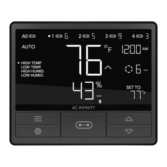
PROGRAMMING 2. MODE BUTTON 1. PORT BUTTON 3. SETTING BUTTON Cycles through the controller’s modes: Cycles through up to four Cycles through the controller’s OFF, ON, AUTO (4 triggers), TIMER to connected devices. Each device settings: DISPLAY, CLOCK, ON, TIMER to OFF, CYCLE (ON and is programmed independently, or °F/°C, CALIB. - Page 18 PROGRAMMING PORTS Pressing the port button will cycle through the controller’s available ports: ALL, 1, 2, 3, and 4. Dot indicates the current device. No digit is displayed if a device is not plugged into the corresponding port. ALL PORTS Navigate to the ALL port to set simultaneous programming for all connected devices.
- Page 19 PROGRAMMING CONTROLLER MODES Pressing the mode button will cycle through the controller’s available programming modes: OFF, ON, AUTO (4 triggers), TIMER TO ON, TIMER TO OFF, CYCLE (On and Off), and SCHEDULE (On and Off). OFF MODE (ALSO SETS MINIMUM LEVEL) Your devices will not run while in this mode.
- Page 20 PROGRAMMING AUTO MODE (HIGH TEMPERATURE TRIGGER) Pressing the up or down button sets the high temperature trigger. The devices will activate if the probe’s reading meets or exceeds this threshold. Once triggered, the devices will gradually ramp up to the level set in ON mode. If the probe’s reading falls below this trigger point, the devices will gradually slow down to a stop or at the level set in Any of the four trigger points can activate while...
- Page 21 PROGRAMMING AUTO MODE (HIGH HUMIDITY TRIGGER) Pressing the up or down button sets the high humidity trigger. The devices will activate if the probe’s reading meets or exceeds this threshold. Once triggered, the devices will gradually ramp up to the level set in ON mode. If the probe’s reading falls below this trigger point, the devices will gradually slow down to a stop or at the level set in Any of the four trigger points can activate while...
- Page 22 PROGRAMMING TIMER TO ON MODE Pressing the up or down button sets a countdown time. Once the timer ends, the devices will trigger to run at the level set in ON Mode. If there is a level set in OFF Mode, the devices will run at that level during the countdown.
- Page 23 PROGRAMMING CYCLE MODE (ON AND OFF) Set an on duration and an off duration for the devices to cycle through continuously. Press the up or down button to first set a duration for the devices to activate. Then press the mode button again and set a duration for the devices to deactivate.
- Page 24 PROGRAMMING SCHEDULE MODE (ON AND OFF) Sets an on clock-time and an off clock-time schedule for the devices to follow daily. Press the up or down button to first set up an on clock-time to trigger ON mode, then press the mode button to set an off clock-time to trigger OFF mode.
- Page 25 PROGRAMMING CONTROLLER SETTINGS Pressing the setting button will cycle through the controller’s available settings: DISPLAY, °F/ °C, CLOCK, CALIB. T°, CALIB. H%, TRANS. T°, and TRANS. H%. DISPLAY SETTING Adjusts the display brightness and auto-dimming. Press the up or down button to cycle through levels 1, 2, 3, A2 and A3;...
- Page 26 PROGRAMMING °F/°C SETTING Changes the displayed units to Fahrenheit or Celsius. Press the up or down button to cycle through F and C. All displayed units will automatically convert when adjusting this setting. CLOCK SETTING Adjusts the current clock time. Press the up or down button to increase or decrease the time.
- Page 27 PROGRAMMING CALIBRATION TEMPERATURE SETTING Adjusts the temperature reading the sensor probe is measuring. Press the up or down button to increase or decrease the data figure in 2°F (or 1°C) increments. The calibration cycle ranges from -20°F to 20°F (or -10°C to 10°C) and will be applied to the sensor probe’s measurements.
- Page 28 PROGRAMMING TRANSITION TEMPERATURE SETTING Customizes how the device will ramp up in levels when triggered ON by temperature in AUTO MODE. Set a transition threshold to determine how much the probe temperature would need to surpass your trigger point for the device to increase in level by one. The higher the transition threshold figure is set to, the more the probe temperature would need to surpass your set temperature trigger for the level to increase.
- Page 29 PROGRAMMING TRANSITION HUMIDITY SETTING Customizes how the device will ramp up in levels when triggered ON by humidity in AUTO MODE. Set a transition threshold to determine how much the probe humidity would need to surpass your trigger point for the device to increase in level by one.
- Page 30 PROGRAMMING ALERT ICONS The alert icons are displayed at the top of the screen. Icons may flash when the controller signals an alert to notify you of any triggered function or alarm. ADVANCE PROGRAMMING Displays when an advance program set in the app is active. "ADV." will appear and override the controller if an automation program is in use.
- Page 31 PROGRAMMING BLUETOOTH Appears when the physical controller is connected to the app via Bluetooth. DISPLAY LOCK ALERT Displays when you lock the controller. The icon will flash and beep if you attempt to adjust the controller while it is still locked. TEMPERATURE/ HUMIDITY ALARM Flashes and beeps with alarm if the temperature/ humdity meet the trigger point set in the app.
-
Page 32: Maximum And Minimum Settings
MAX AND MIN SETTINGS MAXIMUM LEVEL You can determine what level the device will ON MODE run at when its triggered ON. This can be set in ON MODE. The level you leave that mode in will be used as the level the device MAX LEVEL will run at when triggered ON. -
Page 33: Other Settings
OTHER SETTINGS FACTORY RESET Holding the mode, up, and down buttons together for 5 seconds HOLD + will reset your controller and restore factory settings. This clears all user parameters in each controller mode and setting. CONTROLLER LOCK Holding the setting button will lock the controller in your current mode. -
Page 34: Download The App
Open the smart phone camera and scan the QR code below to download the AC Infinity app. Please visit our website at www.acinfinity.com for more information on the AC Infinity app. Please note: The AC Infinity App’s appearance and features are subject to change, and please refer to our website/QR for the latest instructions. -
Page 35: Add A Device
ADD A DEVICE SETUP AND PAIRING Power your device on before pairing your device with the app. Refer to pages 9-10 for more information regarding controller setup. Tap on the “+” tab to To launch the app, tap on the "Smart add your smart device. - Page 36 ADD A DEVICE Hold the port button for 5 seconds to activate Select CONTROLLER 69 to begin pairing. Bluetooth. Wait for the Bluetooth icon to start flashing on your controller’s screen.
- Page 37 ADD A DEVICE Tap DONE button to complete the Your controller will appear in your pairing process. smart device with a unique ID. E-E000E DONE Please note: When pairing the app around multiple controllers, move your mobile device closer to your desired controller.
-
Page 38: Faq
What devices are compatible with the CONTROLLER 69? All AC Infinity devices that contain a UIS connector are compatible. If your AC Infinity device has a 4-pin Molex connector and an EC-Motor, it may still be compatible with the use of an UIS adapter to convert its connector to fit with the controller. - Page 39 CONTROLLER 69 FAQ How do I stop my device from turning on and off too quickly in AUTO MODE? The figure set in the TRANSITION under SETTINGS will determine how the device ramps up in levels when triggered to run in AUTO MODE. Set a transition threshold X. For every multiple of X that has surpassed your trigger point, the device will increase by one level.
- Page 40 CONTROLLER 69 FAQ Will I be able to use this controller with my own fan? The CONTROLLER 69 is only compatible with AC Infinity fans that use EC-motors. Does the controller retain its settings after power is shut off? Yes. If the controller's power is cut off and is powered on afterwards, your settings will remain.
-
Page 41: Other Ac Infinity Products
150 lb. weight capacity. Includes a mounting plate to install your AC Infinity controller onto. Inline Duct Fans The CLOUDLINE series is a line of duct fans designed to quietly ventilate AV rooms and closets, as well as various DIY air circulation and exhaust projects. -
Page 42: Warranty
WARRANTY This warranty program is our commitment to you, the product sold by AC Infinity will be free from defects in manufacturing for a period of two years from the date of purchase. If a product is found to have a defect in material or workmanship, we will take the appropriate actions defined in this warranty to resolve any issues. - Page 43 No part of the materials including graphics or logos available in this booklet may be copied, photocopied, reproduced, translated or reduced to any electronic medium or machine readable form, in whole or in part, without specific permission from AC Infinity Inc.
- Page 44 www.acinfinity.com...
Need help?
Do you have a question about the CONTROLLER 69 and is the answer not in the manual?
Questions and answers