
Subscribe to Our Youtube Channel
Related Manuals for BD FACSymphony A1 Flow


Summary of Contents for BD FACSymphony A1 Flow
- Page 1 FACSymphony™ A1 Flow Cytometer User's Guide 23-23437(01) For Research Use Only 2022-07...
- Page 2 BD. The information in this guide is subject to change without notice. BD reserves the right to change its products and services at any time. Although this guide has been prepared with every precaution to ensure accuracy, BD assumes no liability for any errors or omissions, nor for any damages resulting from the application or use of this information.
-
Page 3: Table Of Contents
Contents 1 ABOUT THIS GUIDE What this guide covers Conventions About the BD FACSymphony™ A1 documentation Instrument technical support 2 INTRODUCTION System overview Cytometer overview Control panel Fluidics system Sheath and waste tanks Optics Workstation 3 CYTOMETER SETUP Starting the cytometer and computer... - Page 4 BD FACSymphony™ A1 Flow Cytometer User's Guide Changing the sheath filter Changing the Bal seal Changing the sample tube O-ring Cleaning or replacing the sheath gasket Accessing the red laser detector array 5 OPTIMIZING CYTOMETER SETTINGS Cytometer settings workflow Verifying the configuration and user preferences...
- Page 5 Contents 11 SUPPLIES AND CONSUMABLES Ordering information Beads Reagents Equipment INDEX...
-
Page 7: About This Guide
About this guide This chapter covers the following topics: What this guide covers (page 8) Conventions (page 8) About the BD FACSymphony™ A1 documentation (page 8) Instrument technical support (page 9) -
Page 8: What This Guide Covers
Help system The help system installed with BD FACSDiva™ software includes the documents listed below. Access the BD FACSymphony™ A1 help system from the Help menu in the BD FACSDiva™ software. Internet access is not required to use the help system. The help system includes the following documents:... -
Page 9: Instrument Technical Support
BD FACSDiva™ Software Reference Manual: Includes instructions or descriptions for installation and setup, workspace components, acquisition controls, analysis tools, and data management. Access this manual from the BD FACSDiva™ Software Help menu (Help > Documentation > Reference Manual), or by double-clicking the shortcut on the desktop. - Page 10 This page intentionally left blank...
-
Page 11: Introduction
Introduction This chapter covers the following topics: System overview (page 12) Cytometer overview (page 13) Control panel (page 15) Fluidics system (page 16) Sheath and waste tanks (page 21) Optics (page 22) Workstation (page 23) -
Page 12: System Overview
System overview About the system The BD FACSymphony™ A1 system includes the BD FACSymphony™ A1 flow cytometer, BD FACSDiva™ software running on the system workstation, the optional BD FACSFlow™ supply system (FFSS), and the ® optional BD High Throughput Sampler (HTS). Each component is described in detail in the following sections. -
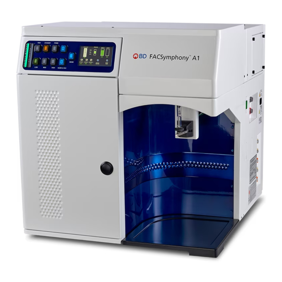
Page 13: Cytometer Overview
Cytometer electronics convert these signals into digital data. Components The following figures show the main components on the front and right side of the BD FACSymphony™ A1 flow cytometer. The descriptions are listed in the tables. Number... - Page 14 BD FACSymphony™ A1 Flow Cytometer User's Guide CAUTION: Xxxxxxxxx ATTENTION: Xxxxxxxxx Network 1 Sheath Level CAUTION: Xxxxxxxxx xxxx xxxxx Network 2 Waste Level ATTENTION: Xxxxxxxxx xxxxx xxxxxx xx xxxxxxxxx XXXXXXXX Xxxx xxxxx xx xxxx xxxx xxx xxx xxx xxxx xx xx x...
-
Page 15: Control Panel
Chapter 2 Introduction Control panel Overview The fluidics display controller enables the monitoring of the sheath tank level, waste tank level, and air pressure status through a combination of status LEDs and text display. It also controls sample flow rate and fluidic controls. -
Page 16: Fluidics System
Cells are carried in the sample core stream in single file and measured individually. Note: If your system has the HTS option, see the BD® High Throughput Sampler User's Guide for additional information on the sample flow rates and fluidic controls. - Page 17 Chapter 2 Introduction The RUN button will also turn orange if the sample tube is cracked or the BAL seal is bad. See Troubleshooting (page 89). STANDBY Stops fluid flow to conserve sheath fluid. When you leave the cytometer for more than a few minutes, place a tube containing less than 1 mL of deionized (DI) water on the sample injection port (SIP) and press STANDBY.
- Page 18 BD FACSymphony™ A1 Flow Cytometer User's Guide Status screen The status screen display is a touchscreen color LCD screen which displays operational data while the system is running and toggles between two different displays: Normal Mode and Setup Mode. Normal Mode displays the current settings of the Fine Adjust Potentiometer, the three programmable potentiometer Set Points, Sheath Tank Pressure Status, Sheath Level, and Waste Level while the system is running.
- Page 19 Chapter 2 Introduction Setup Mode displays the current settings of Sound, FFSS Mode, and Altitude while the system is running. The Setup Mode screen is shown in the following illustation. ALTITUDE SETUP (METERS) 2000 1500 1000 SOUND FFSS -500 SW Revision Ø6 EXIT SETUP Number Definition...
- Page 20 Precautions when using the HTS option When using the BD FACSymphony™ A1 flow cytometer with the HTS, ensure that the HTS is completely pushed into the operating position before removing the droplet containment module (DCM) sleeve or disconnecting the sample coupler from the SIP. This is to avoid accidental leakage of potentially biohazardous liquids directly onto the instrument.
-
Page 21: Sheath And Waste Tanks
Note: Only BD service engineers should change the location of the sheath and waste tanks. If you are using the BD FACSFlow™ supply system (FFSS), see the BD FACSFlow™ Supply System User’s Guide for more information. -
Page 22: Optics
Signal detectors Detector arrays The BD FACSymphony™ A1 detector arrays consist of polygons. Each polygon can be configured with one to six fluorescent detectors. The configuration of detectors may limit the actual number of detectors on each polygon. To access the red laser detector array, see Accessing the red laser detector array (page 49). -
Page 23: Workstation
There are two types of signal detectors in the BD FACSymphony™ A1 flow cytometer: Photomultiplier tubes (PMTs). Used to detect the weaker signals generated by side scatter and all fluorescence channels. - Page 24 This page intentionally left blank...
-
Page 25: Cytometer Setup
Cytometer setup This chapter covers the following topics: Starting the cytometer and computer (page 26) Preparing the sheath tank (page 27) Removing air bubbles (page 29) Preparing the waste tank (page 30) Preparing the fluidics (page 32) About the optical filters and mirrors (page 34) Custom configurations and baselines (page 35) -
Page 26: Starting The Cytometer And Computer
Note: You can turn on the power to the flow cytometer and the workstation in any order. 3. Start BD FACSDiva™ software by double-clicking the shortcut on the desktop, and log in to the software. 4. Check the Cytometer window in BD FACSDiva™ software to ensure that the cytometer is connected to the workstation. -
Page 27: Preparing The Sheath Tank
Preparing the sheath tank Introduction This topic describes how to prepare the sheath tank. Note: If your system is using the BD FACSFlow™ supply system, see the BD FACSFlow™ Supply System User’s Guidefor more information. When to check the sheath tank Check the fluid levels in the sheath tank every time you use the cytometer. - Page 28 Unscrew the clamp knob and push down to loosen, if necessary. Tilt the cap to the side to remove it from the tank. 6. Add up to 10 L of sheath fluid, such as BD FACSFlow™ solution, to the sheath tank. Note: 10 L will reach the interior line on the sheath tank. Do not fill the sheath tank further.
-
Page 29: Removing Air Bubbles
Chapter 3 Cytometer setup More information Removing air bubbles (page 29) Changing the sheath filter (page 43) Cleaning or replacing the sheath gasket (page 49) Removing air bubbles Introduction This topic describes how to remove trapped air bubbles in the sheath filter and the sheath line. Air bubbles can occasionally dislodge and pass through the flow cell, resulting in inaccurate data. -
Page 30: Preparing The Waste Tank
This topic describes how to prepare the waste tank. Prevent waste overflow by emptying the waste tank daily or whenever the system status indicator turns yellow. Note: If your system is connected to the FFSS, see the BD FACSFlow™ Supply System User’s Guide for more information. - Page 31 Chapter 3 Cytometer setup Waste tank components The following figure shows the main components of the waste tank. Number Component Moisture trap User replaceable cap Air line Alarm sensor Waste fluid line Biological precautions Contact with biological specimens and materials can transmit potentially fatal disease. To prevent exposure to biohazardous agents: Put the cytometer in standby mode before disconnecting the waste tank to avoid leakage of biohazardous waste.
-
Page 32: Preparing The Fluidics
BD FACSymphony™ A1 Flow Cytometer User's Guide Procedure To prepare the waste tank: 1. Verify that the flow cytometer is in standby mode. Press the STANDBY button on the control panel if necessary. 2. Disconnect the orange waste tubing from the waste tank. - Page 33 1. Turn on the computer and instrument as described in Starting the cytometer and computer (page 26). ® 2. Install a tube with 3 mL of 1.5% dilution of BD Detergent Solution Concentrate on the SIP and put the tube support arm underneath the tube. ®...
-
Page 34: About The Optical Filters And Mirrors
BD FACSymphony™ A1 Flow Cytometer User's Guide About the optical filters and mirrors Introduction This topic provides a description of the optical filters and mirrors. Filter and mirror configurations Each detector has an optic holder in front of it. The optic holders are labeled with numbers indicating the wavelengths of the bandpass filter and longpass dichroic mirror they contain (for example, 780/60 and 750 LP, respectively). -
Page 35: Custom Configurations And Baselines
Overview BD Cytometer Setup and Tracking (CS&T) software is used to define the baseline performance of your cytometer. A baseline provides a starting point for the tracking of cytometer performance. When running a performance check, you compare the results to the baseline. - Page 36 This page intentionally left blank...
-
Page 37: Maintenance
Maintenance This chapter covers the following topics: Maintenance overview (page 38) Cleaning the fluidics (page 39) Shutting down the cytometer (page 40) Flushing the system (page 40) Replacing the waste tank cap (page 42) Changing the sheath filter (page 43) Changing the Bal seal (page 46) Changing the sample tube O-ring (page 48) Cleaning or replacing the sheath gasket (page 49) -
Page 38: Maintenance Overview
BD FACSymphony™ A1 Flow Cytometer User's Guide Maintenance overview Introduction This topic provides an overview of the BD FACSymphony™ A1 flow cytometer routine maintenance and cleaning procedures. General use guidelines Contact with biological specimens and materials can transmit potentially fatal disease. Follow these guidelines whenever operating or maintaining the cytometer: Wear suitable protective clothing, eyewear, and gloves. -
Page 39: Cleaning The Fluidics
3. Move the tube support arm under the tube (vacuum off) and allow the cleaning solution to run for 5 minutes with the sample flow rate set to HIGH. ® 4. Repeat steps 2 and 3 with a 1.5% dilution of BD Detergent Solution Concentrate. ®... -
Page 40: Shutting Down The Cytometer
Perform the system flush at least every 2 weeks. The flush should be performed more often when the system is first installed or after a major fluidics repair. Note: If you are using the BD FACSFlow™ supply system, see the BD FACSFlow™ Supply System User’s Guide for instructions on flushing the system. - Page 41 Press the PRIME button on the fluidics control panel. b. When the STANDBY button light is amber, press the PRIME button again. 8. Install a tube with 3 mL of BD FACSClean™ on the SIP and put the tube support arm underneath the tube. Maintenance overview (page 38) for other recommended cleaning solutions.
-
Page 42: Replacing The Waste Tank Cap
BD FACSymphony™ A1 Flow Cytometer User's Guide Replacing the waste tank cap Introduction This topic describes how to replace the waste tank cap. Replace the cap once a month. Biological precautions Contact with biological specimens and materials can transmit potentially fatal disease. -
Page 43: Changing The Sheath Filter
Chapter 4 Maintenance Procedure To replace the cap: 1. Put the cytometer in standby mode. 2. Disconnect the orange waste line from the waste tank. 3. Disconnect the alarm sensor line from the alarm sensor socket. Note: Wait at least 30 seconds for pressure to dissipate. 4. - Page 44 BD FACSymphony™ A1 Flow Cytometer User's Guide Sheath filter assembly Number Components Number Components Sheath line to cytometer Filter base Quick-disconnect Quick-disconnect Post-filtered sheath line Sheath fluid line from tank Hose clamp Vent fitting Sheath filter Vent line...
- Page 45 Chapter 4 Maintenance Removing the old filter To remove the old filter: 1. Place the cytometer in standby mode. 2. Remove the sheath filter assembly by pressing the quick-disconnect on both sides of the filter assembly. 3. To replace the standard sheath filter, continue the steps in this section, then move to Attaching the new standard filter (page 45).
-
Page 46: Changing The Bal Seal
BD FACSymphony™ A1 Flow Cytometer User's Guide Changing the Bal seal Introduction This topic describes how to replace the Bal seal. The sample injection tube Bal seal is a ring that forms a seal with the sample tube and ensures proper tube pressurization. - Page 47 Chapter 4 Maintenance Procedure To replace the Bal seal: 1. Remove the outer sleeve from the sample injection tube by turning the retainer counter-clockwise. Slide the outer sleeve down and off of the sample injection tube. Work carefully. The outer sleeve can fall off as you loosen the retainer. See the following illustration. Number Components Bal seal...
-
Page 48: Changing The Sample Tube O-Ring
BD FACSymphony™ A1 Flow Cytometer User's Guide 5. Install a sample tube on the SIP to ensure that the outer sleeve has been properly installed. If the sleeve hits the bottom of the tube, loosen the retainer slightly and push the sleeve up as far as it will go. -
Page 49: Cleaning Or Replacing The Sheath Gasket
Chapter 4 Maintenance 6. Re-install the retainer and the outer sleeve. 7. Install a sample tube on the SIP to ensure that the outer sleeve has been properly installed. If the sleeve hits the bottom of the tube, loosen the retainer slightly and push the sleeve up as far as it will go. - Page 50 This page intentionally left blank...
-
Page 51: Optimizing Cytometer Settings
Optimizing cytometer settings This chapter covers the following topics: Cytometer settings workflow (page 52) Verifying the configuration and user preferences (page 53) Running a performance check (page 55) Setting up an experiment (page 58) Creating application settings (page 62) Recording compensation controls (page 64) Calculating compensation (page 66) -
Page 52: Cytometer Settings Workflow
Manual compensation Compensation setup automatically calculates compensation settings. If you choose to perform compensation manually, not all of the following instructions apply. For detailed instructions, see the BD FACSDiva™ Software Reference Manual. First-time users If you are performing the procedures in this workflow for the first time, you should be familiar with BD FACSDiva™... -
Page 53: Verifying The Configuration And User Preferences
Verifying the configuration and user preferences Introduction This topic describes how to verify the cytometer configuration and user preferences before you create an experiment. To obtain accurate data results, the current cytometer configuration must reflect your BD FACSymphony™ A1 flow cytometer optics. - Page 54 In the Configurations tab, select a configuration. b. Click Set Configuration. c. Click OK. d. Verify that the configuration you just set matches your BD FACSymphony™ A1 flow cytometer optics. 3. Click OK to close the Cytometer Configuration window. 4. Select File > Exit to close CS&T.
-
Page 55: Running A Performance Check
Chapter 5 Optimizing cytometer settings More information Setting up an experiment (page 58) Running a performance check Introduction This topic describes how to run a performance check as part of quality control. Overview The CS&T application is designed to monitor performance on a daily basis and to optimize laser delay. Running a performance check on a regular basis provides a standard for monitoring changes in performance due to degradation of laser power, aging of PMTs, and other potential cytometer service issues. - Page 56 Click Set Configuration and then click OK. 4. Verify that the current configuration has a valid baseline defined. If not, see the BD Cytometer Setup and Tracking Application Guide for more information on defining a baseline. 5. Prepare the CS&T beads according to the technical data sheet provided with the beads or available on the BD Biosciences website (bdbiosciences.com).
- Page 57 Chapter 5 Optimizing cytometer settings If any parameters did not pass, see the BD Cytometer Setup and Tracking Application Guide for troubleshooting information. 12. Select File > Exit to close the CS&T window and return to the BD FACSDiva™ interface. The CST Mismatch dialog opens.
-
Page 58: Setting Up An Experiment
BD FACSymphony™ A1 Flow Cytometer User's Guide Setting up an experiment Introduction This topic describes how to create an experiment in a new folder, specify the parameters of the experiment, and add compensation tubes. Creating an experiment To create an experiment: 1. - Page 59 Chapter 5 Optimizing cytometer settings 2. Make sure the parameters you need appear on the Parameters tab in the Inspector. If more than one parameter is available for a particular detector, you might have to select the one you need from a menu.
- Page 60 BD FACSymphony™ A1 Flow Cytometer User's Guide a. Click the Parameter name to display the available fluorochromes in the Parameters list. b. Select the specific parameter from the menu. Your selection appears as the selected parameter.
- Page 61 Chapter 5 Optimizing cytometer settings c. For this example, select FITC from the menu. 3. Delete any unnecessary parameters.
-
Page 62: Creating Application Settings
BD FACSymphony™ A1 Flow Cytometer User's Guide a. Click the selection button (to the left of the parameter name) to select the parameter. b. Click Delete. The parameter is deleted. Creating application settings Introduction This topic describes how to create application settings. - Page 63 Chapter 5 Optimizing cytometer settings Before you begin Perform the cytometer setup procedure and run a performance check for the configuration that will be used for the application. Procedure To create application settings: 1. In the open experiment, right-click Cytometer Settings in the Browser, then select Application Settings > Create Worksheet.
-
Page 64: Recording Compensation Controls
Recording compensation controls Introduction This topic describes how to create and record compensation controls using the Compensation Setup feature of BD FACSDiva™ software and an experiment with optimized settings. Creating compensation tubes To create compensation control tubes: 1. Select Experiment > Compensation Setup > Create Compensation Controls. - Page 65 Chapter 5 Optimizing cytometer settings Recording compensation settings To record compensation settings: 1. Press RUN and HIGH on the cytometer fluid control panel. 2. Install the unstained control tube onto the SIP. 3. Expand the Compensation Controls specimen in the Browser. 4.
-
Page 66: Calculating Compensation
BD FACSymphony™ A1 Flow Cytometer User's Guide 14. Repeat steps 12 and 13 for the remaining compensation tubes. Next step After you have recorded data for each single-stained control, calculate compensation as described in Calculating compensation (page 66). Calculating compensation Introduction This topic describes how to calculate compensation. -
Page 67: Recording And Analyzing Data
Recording and analyzing data This chapter covers the following topics: Data recording and analysis workflow (page 68) Preparing the workspace (page 68) Recording data (page 69) Analyzing data (page 71) Reusing an analysis (page 75) -
Page 68: Data Recording And Analysis Workflow
You might also need to modify some of the instructions in the procedure. For additional details on completing some of the following steps, see the BD FACSDiva™ Software Reference Manual. Workflow for recording and analyzing data Recording and analyzing data consists of the following steps. -
Page 69: Recording Data
Before you begin Prepare the sample tubes. Note: If you need to run samples at an event rate greater than 10,000 events/second, consider changing your Window extension. See the BD FACSDiva™ Software Reference Manual for more information. Recording data To record data: 1. - Page 70 BD FACSymphony™ A1 Flow Cytometer User's Guide 3. Set the current tube pointer to Beads_001. 4. Click Acquire Data in the Acquisition Dashboard to begin acquisition. 5. While data is being acquired: a. Draw a gate around the singlets on the FSC vs SSC plot.
-
Page 71: Analyzing Data
Chapter 6 Recording and analyzing data 15. Print the experiment-level cytometer settings by right-clicking the Cytometer Settings icon in the Browser and selecting Print. 16. Install a tube with less than 1 mL of DI water onto the SIP. 17. Place the cytometer in standby mode. Analyzing data Introduction This topic describes how to analyze recorded tubes by creating plots, gates, a population hierarchy, and... - Page 72 BD FACSymphony™ A1 Flow Cytometer User's Guide 8. Select all plots, and click the Title tab in the Inspector. 9. Select the Tube and Populations checkboxes to display their names in plot titles. 10. On all fluorescence plots: Make all plots biexponential. Select all fluorescence plots and select the X Axis and Y Axis checkboxes in...
- Page 73 Chapter 6 Recording and analyzing data In the FITC vs PE plot, draw a gate around the FITC-positive population. Name the population FITC positive in the population hierarchy. In the FITC vs PE plot, draw a gate around the PE-positive population. Name the population PE positive in the population hierarchy.
- Page 74 BD FACSymphony™ A1 Flow Cytometer User's Guide Your global worksheet analysis objects should look like the following.
-
Page 75: Reusing An Analysis
Chapter 6 Recording and analyzing data Reusing an analysis Introduction This topic describes how to use a global worksheets to apply the same analysis to a series of recorded tubes. Once you define an analysis for a tube, you can use it to analyze the remaining tubes in the experiment. After viewing the data, print the analysis or save it to a normal worksheet. - Page 76 BD FACSymphony™ A1 Flow Cytometer User's Guide Applying an analysis to normal worksheets You can apply the global worksheet analysis to multiple tubes (on a single normal worksheet) by selecting multiple tubes before pasting the analysis. Ensure that you collapse all tube elements in the Browser before you paste them to multiple tubes.
-
Page 77: Technical Overview
Technical overview This chapterprovides a technical overview of the following topics: About fluidics (page 78) About optics (page 79) About electronics (page 84) -
Page 78: About Fluidics
This topic describes the BD FACSymphony™ A1 flow cytometer fluidics system. Pressure-driven fluidics system The fluidics system in the BD FACSymphony™ A1 flow cytometer operates at a pressure of 5.5 psi. After passing through the sheath filter, sheath fluid is introduced into the lower chamber of the quartz flow cell. -
Page 79: About Optics
Chapter 7 Technical overview About optics Introduction This topic describes the optics system and provides information about: Light scatter (page 79) Fluorescence (page 79) Optical filter theory (page 80) Compensation theory (page 83) Optics system The optics system consists of lasers, optical filters, and detectors. Lasers illuminate the cells or particles in the sample and optical filters direct the resulting light scatter and fluorescence signals to the appropriate detectors. - Page 80 Bandpass (BP) filters Pass a narrow spectral band of light by combining the characteristics of shortpass filters, longpass filters, and absorbing layers. Notch filters Pass all frequencies except those in a stop band centered on a center frequency. They are the opposite of bandpass filters. The BD FACSymphony™ A1 uses LP filters and BP filters.
- Page 81 Chapter 7 Technical overview Longpass (LP) filters LP filters pass wavelengths longer than the filter rating. For example, a 500-LP filter permits wavelengths 500 nm or longer to pass through it and either absorbs or reflects wavelengths shorter than 500 nm. Shortpass (SP) filters An SP filter has the opposite properties of an LP filter.
- Page 82 BD FACSymphony™ A1 Flow Cytometer User's Guide Bandpass (BP) filters A BP filter transmits a relatively narrow range or band of light. BP filters are typically designated by two numbers. The first number indicates the center wavelength and the second refers to the width of the band of light that is passed.
- Page 83 This spillover can be seen in a dot plot of FITC vs PE. The FITC spillover in the PE detector must be corrected as demonstrated in the two figures that follow. Using the Compensation tab of the Cytometer window in BD FACSDiva™ software, you can adjust the PE-%FITC spectral overlap value. Compensation is optimal when the positive and negative FITC populations...
-
Page 84: About Electronics
FITC spillover into the PE detector remains constant. About electronics Introduction This topic describes the electronics in the BD FACSymphony™ A1 flow cytometer. Pulse As cells or other particles pass through a focused laser beam, they scatter the laser light and can emit fluorescence. - Page 85 Chapter 7 Technical overview 1. A pulse begins when a particle enters the laser beam. At this point, both the beam intensity and signal intensity are low. 2. The pulse reaches a maximum intensity or height when the particle reaches the middle of the beam, where the beam and signal intensity are the brightest.
- Page 86 These parameters are set by BD Biosciences service personnel during instrument installation and performance check and are updated each time you run a performance check. Note: Do not otherwise change the settings in the Laser tab unless instructed to do so by BD Biosciences. Changing the settings affects your data.
- Page 87 Chapter 7 Technical overview More information Running a performance check (page 55)
- Page 88 This page intentionally left blank...
-
Page 89: Troubleshooting
Troubleshooting This chapter covers the following topics: Cytometer troubleshooting (page 90) Electronics troubleshooting (page 95) -
Page 90: Cytometer Troubleshooting
BD FACSymphony™ A1 Flow Cytometer User's Guide Cytometer troubleshooting Introduction This topic describes possible problems and recommended solutions for BD FACSymphony™ A1 flow cytometer issues. Droplets are visible on the SIT Possible causes Recommended solutions Worn O-ring in the retainer Replace the O-ring. See Changing the sample tube O-ring (page 48). - Page 91 Set the PMT voltage higher for the threshold parameter. parameter is set too low Gating issue See the BD FACSDiva™ Software Reference Manual for information on setting gates. Air in the sheath filter Purge the filter. See Removing air bubbles (page 29).
- Page 92 Possible causes Recommended solutions Air bubbles in the sheath Remove the air bubbles. See Removing air bubbles (page 29). filter or flow cell Threshold level is too low Increase the threshold level. See the BD FACSDiva™ Software Reference Manual for instructions.
- Page 93 Prime the fluidics system. See Preparing the fluidics (page 32). flow cell PMT voltage for the Set the PMT voltage higher for the threshold parameter. See the BD FACSDiva™ Software threshold parameter is set Reference Manual for instructions. too low Sample is not adequately Mix the sample to suspend the cells.
- Page 94 BD FACSymphony™ A1 Flow Cytometer User's Guide Distorted scatter parameters Possible causes Recommended solutions Cytometer settings are Optimize the scatter parameters. See the BD FACSDiva™ Software Reference Manual for improperly adjusted instructions. Air bubble in the sheath filter Purge the air from the filter. See Removing air bubbles (page 29).
-
Page 95: Electronics Troubleshooting
Laser is not functioning Contact BD Biosciences. Optical alignment problem Contact BD Biosciences. Electronics troubleshooting Introduction This topic describes possible problems and recommended solutions for BD FACSymphony™ A1 electronics issues. “Cytometer Disconnected” in cytometer window Possible causes Recommended solutions Cytometer power is off Turn on the cytometer main power. - Page 96 This page intentionally left blank...
-
Page 97: Detector Array Configurations
Detector array configurations This chapter covers the following topics: Fluorescence spectra (page 98) About configuration maps (page 99) About configurations (page 100) Base configuration polygon maps (page 101) -
Page 98: Fluorescence Spectra
You can also look for training by selecting Support > Training. Designing multicolor panels The BD FACSymphony™ A1 flow cytometer is designed specifically for multicolor research. Results depend on the excitation and emission spectra of the individual dye, the number of fluorescently labeled binding sites on the cell, as well as spectral overlap and spillover to other detectors. -
Page 99: About Configuration Maps
Chapter 9 Detector array configurations Definition Violet (405 nm) Blue (488 nm) Yellow-Green (561 nm) Red (637 nm) About configuration maps Filter and mirror arrangement The filters are arranged in the detector array to steer progressively shorter wavelengths of light to the next detector in the array. -
Page 100: About Configurations
About configurations Available configurations The configurations for the BD FACSymphony™ A1 flow cytometer supports detectors, filters, and mirrors for four lasers to provide either 14 or 16 colors. The Small Particle Detector can be added to either the 14 or 16 color configuration. -
Page 101: Base Configuration Polygon Maps
Detector LP mirror BP filter Fluorochromes 780/60 BD Horizon™ BV786 Violet 710/50 BD Horizon™ BV711 405 nm 670/30 BD Horizon™ BV650 610/20 BD Horizon™ BV605 525/50 BD Horizon™ BV480 450/50 BD Horizon™ BV421, BD Horizon™ BV450, Pacific Blue™ Optional: 431/28... - Page 102 Note: Because there are no fluorochromes associated with detectors A and D, the configuration displayed by BD FACSDiva™ does not indicate the existence of mirrors for these detectors, but mirrors are installed during manufacture to direct the laser beam along the path A-B-C-D-E/F.
- Page 103 The following table and map shows the five-color configuration for the 561-nm yellow-green laser. Note: Detector C is not used in the 14-color configuration. Laser Detector LP mirror BP filter Fluorochromes 780/60 PE-Cy7 Yellow-Green 710/50 PE-Cy5.5 561 nm 670/30 PE-Cy5 610/20 BD Horizon™ PE-CF594, PE- Texas Red, PI 586/15...
- Page 104 BD FACSymphony™ A1 Flow Cytometer User's Guide Three-color red laser configuration The following table and map shows the three-color configuration for the 637-nm red laser. Note: Detector B is not used in the 14-color configuration. Laser Detector LP mirror BP filter...
-
Page 105: Small Particle Detector
Small Particle Detector This chapter covers the following topics: Overview (page 106) SPD components (page 106) Preparing the system for small particle detection (page 107) Confirming small particle detection (page 109) Aligning the small particle detector (page 113) Small particle detector troubleshooting (page 116) -
Page 106: Overview
This device can be included as an option on a new or existing system. Note: The SPD is a separate device installed inside the BD FACSymphony™ A1 flow cytometer, and the output is captured on the blue laser detector array. For more information, see the blue laser configuration map in... -
Page 107: Preparing The System For Small Particle Detection
Detergent Solution Concentrate must be diluted before use. Mix one full 15 mL bottle of ® Detergent Solution Concentrate into 985 mL of DI water to make 1 L total. Filtered DI water Filtered diluent (0.2 µm-filtered 1X PBS) ® CS&T Beads BD FACSFlow™ sheath fluid (do not use sheath fluid with surfacant) - Page 108 5. Install a tube with 3 mL of filtered diluent on the SIP. Press RUN and LOW on the cytometer fluidic control panel for the remainder of the system stabilization time. 6. Ensure that the cytometer configuration windows extension is set to 4. Refer to the BD Cytometer Setup and Tracking Application Guide for details.
-
Page 109: Confirming Small Particle Detection
PMT voltages, you can save the cytometer settings for use as application settings. Setting up the SPD QC experiment 1. In the BD FACSDiva™software, create a new experiment and add a specimen. 2. Add two tubes to the specimen. 3. Rename the first tube to MegaMix beads and rename the second tube to Diluent background. - Page 110 1. If the SPD QC experiment created using the previous procedure has been closed, reopen it. 2. Vortex a Megamix-Plus SSC beads vial and add 500 µL of the bead solution to a clean BD FACS™ tube. 3. Install the Megamix tube and acquire the sample on LOW.
- Page 111 Chapter 10 Small Particle Detector 5. Align detector as described in Aligning the small particle detector (page 113). 6. Adjust the voltage for the SP SSC parameter until the median of 200 nm bead population is at channel 10 The bead peak at 500 nm will be off-scale and the bead peak at 240 nm will be either off-scale or close to it. Position the 200 nm bead gate to fully encompass the 200 nm population.
- Page 112 MegaMix-Plus beads before checking the background noise. The following procedure assumes that the system is currently running on LOW with a tube of MegaMix-Plus mixture or filtered diluent on the SIP. ® 1. Prepare a tube with 3 mL of a 1.5% dilution of BD Detergent Solution Concentrate. See Required materials (page 107).
-
Page 113: Aligning The Small Particle Detector
Chapter 10 Small Particle Detector 4. Acquire and observe the threshold rate for 5 minutes. a. If the event rate stops decreasing, record 1 minute of data for the filtered diluent on LOW. b. If the event rate does not decrease, see Small particle detector troubleshooting (page 116). - Page 114 BD FACSymphony™ A1 Flow Cytometer User's Guide 6. In the Relative steps area, you can select – (minus) or + (plus) to move the motor stage in small increments. 7. While acquiring your MegaMix-Plus bead mixture and examining the SP SSC-H v BB515-H plot and SP-SSC-H histogram, move the motors one step at a time.
- Page 115 Chapter 10 Small Particle Detector The following plot diagrams and statistics views represent an example after alignment using Picomotor Application: 8. After alignment, close the New Focus Picomotor Application and return to Setting up PMT voltages for small particles (page 110).
-
Page 116: Small Particle Detector Troubleshooting
BD FACSymphony™ A1 Flow Cytometer User's Guide Small particle detector troubleshooting Event rate or background noise is higher than expected Possible causes Recommended solutions Your sample diluent may be 1. Acquire filtered diluent on LOW and observe event rate for 5 minutes. If event rate is the source of the noise or decreasing, continue to run until desired rate is achieved or rate stops falling. -
Page 117: Supplies And Consumables
Supplies and consumables This chapter covers the following topics: Ordering information (page 118) Beads (page 118) Reagents (page 118) Equipment (page 119) -
Page 118: Ordering Information
BD FACSymphony™ A1 Flow Cytometer User's Guide Ordering information To order spare parts and consumables from BD Biosciences: Within the US, call (877) 232-8995. Outside the US, contact your local BD Biosciences customer support representative. Worldwide contact information can be found at bdbiosciences.com. Beads Introduction This topic lists the QC and CS&T beads available. -
Page 119: Equipment
® Detergent Solution BD Biosciences 660585 Concentrate BD FACSClean™ solution BD Biosciences 340345 Dyes and fluorochromes BD Biosciences, Sigma, or Life Technologies – ® Chlorine bleach Clorox or other major supplier (to ensure that – (5% sodium hypochlorite) the bleach is at the correct concentration and... - Page 120 This page intentionally left blank...
-
Page 121: Index
101 documentation 8 flow cytometer overview 12 lasers and optics 22 637-nm red laser 104 BD High Throughput Sampler (HTS) 12, 16, 20, 90 BD Horizon fluorochromes 101 blank optical holders 35 acridine orange (AO) 39 bleach 38, 119... - Page 122 BD FACSymphony™ A1 Flow Cytometer User's Guide containers sheath 21, 27 electronics waste 21, 30, 32 digital 86 control panel, cytometer 15 laser controls 86 controls pulse 84 fluidics 15 pulse measurements 85 single-stained 53, 68 threshold 86 conventions troubleshooting 95...
- Page 123 Index fluidics 78 flow rate control buttons 17 immunophenotyping fluid control buttons analysis 71 PRIME 17 experiment 68 RUN 16 hydrodynamic focusing 78 STANDBY 17 fluidics description 16, 78 lasers flow rate control 17 performance check 55 flushing system 40 quality control (QC) particles 118 preparing 32 wavelengths and power 22...
- Page 124 BD FACSymphony™ A1 Flow Cytometer User's Guide filters 22, 80 optimization, sample 52 safety symbol definitions 8 ordering spare parts 118 safety symbols 8 sample optimization 52 Pacific Blue fluorochrome 101 optimization experiment 58 particles 118 optimization, single-stained controls 53, 68...
- Page 125 Index small particle detector Picomotor application 113 troubleshooting 116 software cytometer control 8 version 23 spare parts, ordering 118 spillover 83 SSC See side scatter 79 STANDBY, fluid control button 17 starting cytometer 26 statistics views 71 Stokes shift 79 support, technical 9 technical assistance 9 thiazole orange (TO) 39...
- Page 126 Becton, Dickinson and Company BD Biosciences 2350 Qume Drive San Jose, California 95131 USA BD Biosciences European Customer Support Tel +32.53.720.600 help.biosciences@bd.com bdbiosciences.com ResearchApplications@bd.com...
Need help?
Do you have a question about the FACSymphony A1 Flow and is the answer not in the manual?
Questions and answers