socomec DIRIS A-40 Instruction Manual
Pmd - multifunction meter
Hide thumbs
Also See for DIRIS A-40:
- Operating instruction (100 pages) ,
- Operating instructions manual (80 pages) ,
- Technical manual (27 pages)

Related Manuals for socomec DIRIS A-40


Summary of Contents for socomec DIRIS A-40
- Page 1 DIRIS A-40 PMD - Multifunction meter www.socomec.com/ catalogues-brochures_en.html...
-
Page 2: Table Of Contents
. . . . . . . . . . . . . . . . . . . . . . . . . . . . . . . . . . . . . . . . . . . . . . .43 DIRIS A-40 - 545802B - SOCOMEC... -
Page 3: Documentation
. . . . . . . . . . . . . . . . . . . . . . . . . . . . . . . .57 1. DOCUMENTATION All documentation on the DIRIS A-40 is available on the website at the following address: www.socomec.com/catalogues-brochures_en.html DIRIS A-40 - 545802B - SOCOMEC... -
Page 4: Hazards And Warnings
The assembly, use, servicing and maintenance of this product must only be carried out by trained, qualified professionals. SOCOMEC shall not be held responsible for failure to comply with the instructions in this manual. 2.1. Risk of electrocution, burns or explosion Caution: risk of electric shock Ref. -
Page 5: Responsibility
• Any cable which needs to be replaced may only be replaced with a cable having the correct rating. • Despite constantly striving for quality in preparing this manual, errors or omissions are always a possibility and are not the responsibility of SOCOMEC. DIRIS A-40 - 545802B - SOCOMEC... -
Page 6: Preliminary Operations
• The device has not been damaged during transit, • The device part number conforms to your order • The package includes: - 1 device equipped with removable terminals - 1 line resistor (ref. 4899 0019) - 1 Quick Start guide DIRIS A-40 - 545802B - SOCOMEC... -
Page 7: Introduction
4 .1 .1 . Range DIRIS A-40 Ref. 4825 0500 : Model with Modbus communication Ref. 4825 0501 : Model with Modbus + Ethernet communication Ref. 4825 0502 : Model with Modbus + Profibus communication DIRIS A-40 - 545802B - SOCOMEC... -
Page 8: Principle
4 .1 .2 . Principle Current sensors TE, TR or TF DIRIS A-40 - 545802B - SOCOMEC... -
Page 9: Functions
- 4 quadrant operation - Predictive power - Overall accuracy of the DIRIS A-40 + Sensors measurement chain guarantees up to class 0.5 (depending on the current sensor used) in power and active energy in accordance with IEC 61557-12 • Quality... - Page 10 Average values • Web Server Power & Energy Monitoring • Communication RS485 RTU Modbus • RS485 Modbus RTU and Profibus • DPV1 RS485 Modbus RTU and Ethernet • (Modbus TCP, BACnet) SNTP, SMTP, FTP • DIRIS A-40 - 545802B - SOCOMEC...
-
Page 11: Dimensions
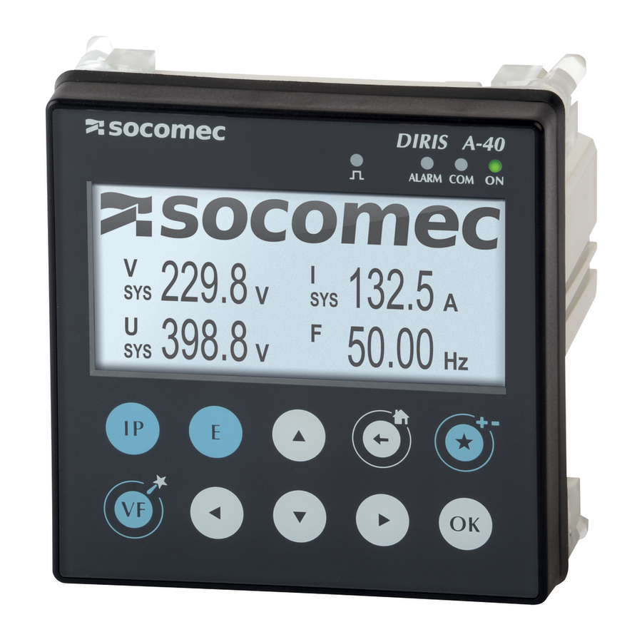
4 .1 .4 . Dimensions Dimensions : in/mm 3.58 2.67 0.62 67 .8 15 .8 3.88 98 .5 4 .1 .5 . Front panel 1. Screen 350x160 2. LEDs 3. 10 capacitive touch keys DIRIS A-40 - 545802B - SOCOMEC... - Page 12 - Flashing: communication in progress on the RS485 bus - Off: device is off - On: product working OK NOTE: When the 4 LEDs are flashing: a problem has been detected in the device DIRIS A-40 - 545802B - SOCOMEC...
-
Page 13: Presentation Of Associated Current Sensors
4.2. Presentation of associated current sensors Various types of current sensors are connected to the DIRIS A-40: solid-core (TE), split-core (TR, iTR) or flexible (TF). The variety between these sensors means they can be adapted to any type of new, existing or high-current existing installation. -
Page 14: Te Solid-Core Current Sensors
(cable, flexible or rigid busbar) or on a DIN rail support or plate. Thanks to the specific link, they are recognised by the DIRIS A-40 and a high level of overall accuracy for the measurement chain is guaranteed. - Page 15 1.61 x 1.61 ø 8.4 13.5 x 13.5 21 x 21 31 x 31 41 x 41 0.69 0.69 0.77 0.85 17.5 17.5 19.5 21.5 3.54 0.08 0.97 24.6 2.52 / 64 0.77 19.7 1.42 TE-90 DIRIS A-40 - 545802B - SOCOMEC...
-
Page 16: Tr / Itr Split-Core Current Sensors
The TR / iTR split-core current sensors are used to set up measurement points in a new or existing installation without interfering with its cabling. Thanks to the specific link, they are recognised by the DIRIS A-40 and the overall accuracy of the measurement chain is guaranteed. -
Page 17: Tf Flexible Current Sensors
Due to the specific RJ12 connection, the TF current sensors can only be used with DIRIS Digiware I, DIRIS B and DIRIS A-40. Used in conjunction with these PMD equipped with RJ12 connectors, the overall accuracy of the measurement chain is guaranteed. -
Page 18: Adapters For 5A Sensors
5A adapter I nom. 5 A I max. 6 A Reference 4829 0599 4.2.4.2. Dimensions ØW ØW 5A adapter Dimensions in/mm 1.10 x 0.79 x 1.77 LxHxD 28 x 20 x 45 Aperture ø 0.33 ø 8.4 DIRIS A-40 - 545802B - SOCOMEC... -
Page 19: Installation
• Avoid vibrations with accelerations greater than 1 g for frequencies lower than 60 Hz. • The device must not be cleaned. • Do not install outdoor. 5.2. Installing DIRIS A-40 The DIRIS A-40 is to be fitted onto a door with a 92x92 mm cutout. Dimensions: in/mm DIRIS A-40 - 545802B - SOCOMEC... -
Page 20: Installing Te Solid-Core Sensors
TE-25 25 mm 4829 0502 TE-35 35 mm 4829 0503 TE-45 45 mm 4829 0504 TE-55 55 mm 4829 0505 TE-90 90 mm 4829 0506 5 .3 .2 . DIN rail mounting TE-18 -> TE-55 DIRIS A-40 - 545802B - SOCOMEC... - Page 21 TE-90 Removing clamps NB: Fix sensor TE-90 to the DIN rail to make it easier to install. This is a temporary installation. Use the clamps to install the TE-90 sensors on the DIN rail. DIRIS A-40 - 545802B - SOCOMEC...
-
Page 22: Plate Mounting
5 .3 .3 . Plate mounting TE-18 diameter 0.17 / 4.2 M4 max 1 Nm 1.05 26.8 0.81 20.5 TE-25 - > TE-55 diameter 0.20 / 5.2 M5 max 1 Nm DIRIS A-40 - 545802B - SOCOMEC... - Page 23 TE-90 Removing clamps diameter 0.20 diameter 5 .2 NB: Use the clamps to install the TE-90 sensors on the board. DIRIS A-40 - 545802B - SOCOMEC...
-
Page 24: Installing On A Cable With Clamping Collar
NB: Use the clamps to install the TE-90 sensors on a cable with clamping collar. Do NOT clamp or pull out NON-INSULATED conductors carrying DANGEROUS VOLTAGE which could cause an electric shock, burn or arc flash. Ref. IEC 61010-2-032 DIRIS A-40 - 545802B - SOCOMEC... -
Page 25: Bar Mounting
The jaws must be per- pendicular to the holding notches . Do NOT clamp or pull out NON-INSULATED conductors carrying DANGEROUS VOLTAGE which could cause an electric shock, burn or arc flash. Ref. IEC 61010-2-032 DIRIS A-40 - 545802B - SOCOMEC... -
Page 26: Sensors Assembly
Linear assembly Staggered assembly Reference 4829 0598 These accessories must be ordered separately. 5 .3 .7 . Sealing accessories for sensors Reference Sealing case for terminal 4829 0600 These accessories must be ordered separately. DIRIS A-40 - 545802B - SOCOMEC... -
Page 27: Installing Tr Split-Core Sensors
Do NOT clamp or pull out NON-INSULATED conductors carrying DANGEROUS VOLTAGE which could cause an electric shock, burn or arc flash. Ref. IEC 61010-2-032 Before closing the TR sensor, check that the air gap is clean (no contamination or corrosion) DIRIS A-40 - 545802B - SOCOMEC... -
Page 28: Installing Tf Flexible Current Sensors
Centred position for the best measurement Do NOT clamp or pull out NON- INSULATED conductors carrying DANGEROUS VOLTAGE which could cause an electric shock, burn or arc flash. Centred position for the best measurement Ref. IEC 61010-2-032 DIRIS A-40 - 545802B - SOCOMEC... -
Page 29: Installing The 5A Adapter
5.6. Installing the 5A adapter 5A secondary current transformer Do NOT clamp or pull out NON-INSULATED conductors carrying DANGEROUS VOLTAGE which could cause an electric shock, burn or arc flash. Ref. IEC 61010-2-032 DIRIS A-40 - 545802B - SOCOMEC... -
Page 30: Connection
ETHERNET (Ref 4825 0501) PROFIBUS (Ref 4825 0502) x= 8 mm 0.6 N.m max. 0.2 mm² - 4 mm² SELV: Safety Extra Low Voltage DIRIS A-40 ref. 4825 0500 DIRIS A-40 ref. 4825 0502 Communication PROFIBUS DIRIS A-40 - 545802B - SOCOMEC... - Page 31 9: NC Mac address: XX:XX:XX:XX:XX:XX OUTPUT 1+ 1- 2+ 2- Means to prevent loosening of the conductors must be fitted on the nearest of the connections. TE/TR/TF SENSORS I 01 I 02 I 03 DIRIS A-40 - 545802B - SOCOMEC...
-
Page 32: Connection To The Electrical Network And To The Loads
6.2. Connection to the electrical network and to the loads The DIRIS A-40 can be used on single-phase, two-phase or three-phase networks. 6 .2 .1 . Configurable loads based on the network type The table below summarises the load that it is possible to configure depending on the type of network at the installation. - Page 33 V1 V2 V3 VN V1 V2 V3 VN V1 V2 V3 VN V1 V2 V3 VN V1 V2 V3 VN Fuse: 0.5 A gG / 0.5 A class CC DIRIS A-40 - 545802B - SOCOMEC V1 V2 V3 VN V1 V2 V3 VN...
-
Page 34: Communication
A 120 Ohm resistor must be fixed at both ends of the connection. 7.3. Modbus and Profibus communication tables The Modbus and Profibus communication tables and the associated explanations are available on the DIRIS A-40 documentation page on the website at the following address: DIRIS A-40 - 545802B - SOCOMEC... -
Page 35: Configuration
8. CONFIGURATION The device can be configured directly from the DIRIS A-40 screen or with the Easy Config software. The following paragraphs describe configuration with Easy Config for different types of communication architecture and several types of connected SOCOMEC products. - Page 36 DIRIS G DIRIS Digiware C-31 A-40 RS485 Configuration using Easy Config via a DIRIS D-50 / D-70 monitor (Ethernet) Easy Config DIRIS A-40 Ethernet RS485 DIRIS DIRIS B-30 DIRIS Digiware D-50 / D-70 A-40 RS485 DIRIS A-40 - 545802B - SOCOMEC...
-
Page 37: Using Easy Config
8 .1 .2 . Using Easy Config Easy Config is configuration software used to set product parameters easily and quickly. Parameters are set in successive steps: For each setting selected a customised screen appears, depending on the connected product (2). DIRIS A-40 - 545802B - SOCOMEC... - Page 38 The user selects the nominal voltage, the network frequency, the direction of phase rotation and whether or not a voltage transformer is used. Calculation method The integration period and the synchronisation methods of the different electric parameters are defined on this screen. DIRIS A-40 - 545802B - SOCOMEC...
- Page 39 The other settings, such as Memory allocation, Multi-tariff, Inputs/Outputs, Quality events, Communication and other controls are also carried out with Easy Config. Example of the screen for setting the Quality parameters of the electrical network: DIRIS A-40 - 545802B - SOCOMEC...
-
Page 40: Configuration From The Display
EVENTS WIZARD CONFIG PARAMETERS . . . The wizard begins by choosing the language and allows configuration of the main parameters of the DIRIS A-40 by means of a series of screens: • Date/time • Load type • Integration period •... -
Page 41: Complete Configuration
Enter the password "100" using the arrow pad (4 arrow keys) and confirm with "OK": HOME LOADS MEASURES EVENTS CODE PARAMETERS ABOUT this gives access to the whole configuration of the DIRIS A-40: PARAMETERS DISPLAY LOAD SENSORS CALCULATION INPUTS/OUTPUTS …... - Page 42 • LOAD CURVES: settings of the integration period, synchronisation and selection of the calculated load curves • CONSUMPTION CURVES: settings of the integration period and synchronisation of the consumption curves • ALARMS CONFIGURATION: configuration of the alarms • METRO LED:settings of the metrological LED parameters DIRIS A-40 - 545802B - SOCOMEC...
-
Page 43: Screen Menu Structure
Alarm on instantaneous measurement, Alarm on digital input, System alarm Metrological LED Choice of energy allocated to the LED (Ea+, Ea-, Er+, Er-, Es) IP address MAC address About Serial number Software version Reboot Note: the menus available depend on the product models. DIRIS A-40 - 545802B - SOCOMEC... -
Page 44: Use
Use this to remove favourite screens by holding down 9.4. Screen display of measurements The instantaneous and/or mean values are displayed depending on the types of measurement, shown as a numerical value or in graphic form. DIRIS A-40 - 545802B - SOCOMEC... -
Page 45: Alarms
• Alarms on voltage unbalances: Unba, Unb • Alarm upon current unbalance: Inba, Inb • Selection of the hysteresis and high/low threshold • Setting a time delay at the start and end of the alarm DIRIS A-40 - 545802B - SOCOMEC... -
Page 46: 50160 Voltage Quality Events
• Setting a time delay at the start and end of the alarm Example of configuring an alarm on a digital input via Easy Config: 10.1.6. Combination of alarms • 4 boolean combinations (OR, AND) on the defined alarms (electrical values, energy, inputs, etc.) DIRIS A-40 - 545802B - SOCOMEC... -
Page 47: System Alarms
• Fixed: Alarm upon event (takes priority if there is a system alarm at the same time) 10.3.2. Activation of an output • If an output is present on the product, it can be activated when an alarm is detected DIRIS A-40 - 545802B - SOCOMEC... -
Page 48: Activation Of An Input
10.3.4. RS485 Modbus • Information on the alarms with timestamping available via the RS485 communication bus • Sends alarm acknowledgement 10.3.5. Screen and WEBVIEW • Information on the alarms with timestamping • Sends alarm acknowledgement DIRIS A-40 - 545802B - SOCOMEC... -
Page 49: Web Server
11. WEB SERVER The Ethernet version of the DIRIS A-40, reference 4825 0501, has an embedded web server. This web server allows access to all the measurements of the electrical parameters and of the energy measured by the DIRIS A-40. -
Page 50: Characteristics
Secondary: 60, 100, 110, 173, 190 VAC Input consumption ≤ 0,1 VA Accuracy of voltage measurement Class 0.2 Connection Removable spring-cage terminal block, 4 positions, 0.5 - 2.5 mm² solid cable or 0.25 - 1.5 mm² stranded cable with end piece DIRIS A-40 - 545802B - SOCOMEC... -
Page 51: Input/Output Characteristics
Sends a mail in case of an alarm FTP protocol Saves the measurement files on an FTP server Functions Data configuration and reading Connection RJ45 port PROFIBUS Product DIRIS A-40 ref. 4825 0502 Link RS485 - SELV Protocol PROFIBUS DPV1 DIRIS A-40 - 545802B - SOCOMEC... -
Page 52: Environmental Specifications
40% for 10/12 cycles Criterion A 70% for 25/30 cycles Criterion A Short interruption: 0% for 250/300 cycles Criterion C Radiated emissions CISPR11 Gr:1 - CLASS A Conducted emissions CISPR11 Gr:1 - CLASS B DIRIS A-40 - 545802B - SOCOMEC... -
Page 53: Safety
Installation category III (300VAC Ph/N), degree of pollution 2 UL61010-1 & UL61010-2-030 UL installation: DIRIS A-40 and current sensors have to be enclosed inside an NRTL certified electrical/fire enclosure, Listed Industrial Control Equipment, or similar equipment. 12 .1 .9 . Service life MTTF (mean time to failure) >... -
Page 54: Te, Tr / Itr And Tf Sensor Characteristics
< 2,000 m PEP ecopassport - ISO 14025 TE sensors: SOCO-2014-03-v1-fr, SOCO-2014-03-v1-en UL 61010 Connection SOCOMEC RJ12 cable, straight, twisted pair, unshielded, 600 V -10 / +70 °C - SELV (1) > 1000 A with adapter TC 5 A. TE - closed sensor TE-90 Model TE-90 Nominal current range In 600 A - 2000 A... - Page 55 95% RH without condensation Altitude < 2,000 m PEP ecopassport - ISO 14025 SOCO-00007-V01.01-EN UL 61010 Connection SOCOMEC RJ12 cable, straight, twisted pair, unshielded, 600 V -10 / +70 °C - SELV TF - Flexible current sensor Model TF-55 TF-120 TF-300 Nominal current range In (A)
-
Page 56: Performance Classes
1 with TE, TR, iTR or TF sensors Orders 1 to 63 THD-Ri to the fundamental, relative to the efficient value) Current harmonics 1 with TE, TR, iTR or TF sensors Centralised remote control signals *With SOCOMEC connection cables. DIRIS A-40 - 545802B - SOCOMEC... -
Page 57: Evaluation Of The Power Supply Quality
Voltage interruption (Lp-Lg or Lp-N) Unba Voltage amplitude unbalance (Lp-N) Voltage phase and amplitude unbalance (Lp-Lg or Lp-N) Voltage harmonics Current harmonics 1 with TE, TR, iTR or TF sensors Centralised remote control signals DIRIS A-40 - 545802B - SOCOMEC... - Page 58 CORPORATE HQ CONTACT: SOCOMEC SAS 1-4 RUE DE WESTHOUSE 67235 BENFELD, FRANCE www.socomec.com 545802B...
Need help?
Do you have a question about the DIRIS A-40 and is the answer not in the manual?
Questions and answers