Advertisement
Advertisement
Table of Contents

Related Manuals for ML Accessories FL8ABK


Summary of Contents for ML Accessories FL8ABK
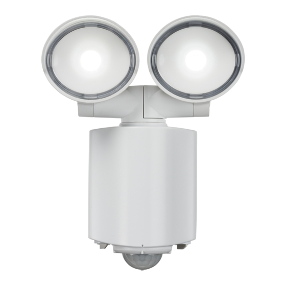
- Page 1 INSTALLATION & MAINTENANCE MANUAL FL8ABK / FL8AW / FL16ABK / FL16AW...
- Page 2 These instructions should be used to aid installation of the following products: FL8ABK / FL8AW / FL16ABK / FL16AW SAFETY • This product must be installed in accordance with the latest edition of the IEE Wiring Regulations (BS7671) and current Building Regulations.
- Page 3 Remove the rear panel with the aid of a flat-head screwdriver (see Fig. 1 • ve the rear panel with the aid of a flat-head screwdriver (see Fig. 1) Fig. 1 • Mark the location of the fixing holes and drill the holes ensuring not to infringe with any gas/water pipes or Fig.
- Page 4 Fig. 3 • Fig. 3 See below for sensor settings • Switch on and check for correct operation See below for sensor settings Switch on and check for correct operation Fig. 3 SENSOR SETTINGS See below for sensor settings • SENSOR SETTINGS Switch on and check for correct operation •...
- Page 5 Fig. 4 Once the detection area is verified, the sensor duration can be set via the TIME dial - from a minimum of 10 Once the detection area is verified, the sensor duration can be set via the TIME dial - from a minimum of 10 seconds to a maximum of 15 minutes.
- Page 6 If this product should fail within its warranty period, it should be returned to the place of purchase for a free of charge replacement. ML Accessories does not accept responsibility for any installation costs associated with the replacement product. Your statutory rights are not affected. ML Accessories reserve...
- Page 7 Specific zones within the detection area can be blocked if required by using the blanking inserts provided (see Fig. 6). Each section of blanking insert covers a zone of a 300° angle. Fig. 6 Fig. 6 WARNING This product must be disconnected from the circuit if subjected to any high voltage or insulation resistance testing.
- Page 8 INTERNAT CONTACT D INTERNATIONAL CONTACT DETAILS >80 40°C ML Accessories Limited LU5 4LT www.mlaccessories.co.uk DCOCT21_V1...
Need help?
Do you have a question about the FL8ABK and is the answer not in the manual?
Questions and answers