
Related Manuals for ELMEKO PK 150 PS-C


Summary of Contents for ELMEKO PK 150 PS-C
- Page 1 PK 150 PS-C / PK 150 PS-C+AG PELTIER-KÜHLGERÄT THERMOELECTRIC COOLER Montage- und Betriebsanleitung Installation and Operating Manual...
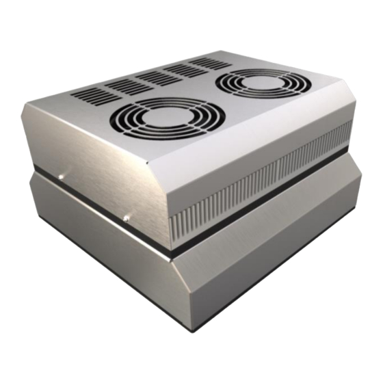
- Page 2 Regler TRP 205 Controller TRP 205 Schraubbrücke Screw bridge Netzanschluss Power supply *Abbildung auf der Titelseite zeigt Peltier-Kühlgerät mit und ohne Aufbaugehäuse Illustration on the title page shows Thermoelectric cooler with and without additional housing...
-
Page 3: Table Of Contents
INHALTSVERZEICHNIS TABLE OF CONTNENTS Anwendung Application ..................................4 Technische Daten Technical data ..............................4 Beschreibung Description ................................... 5 Eigenschaften Features ..................................5 Berechnungsprogramm DELTA T Calculation software DELTA T ..................5 Montage Installation ..................................... 6 Abmessungen ohne Aufbaugehäuse Dimensions without additional housing ............ -
Page 4: Anwendung Application
The high efficiency contributes additionally to the eco-friendliness. With the integrated controller cooling and heating is possible. TECHNISCHE DATEN TECHNICAL DATA Bezeichnung Type PK 150 PS-C PK 150 PS-C+AG Artikelnummer Part number 40 P15 57HPSC 40 P15 57HPSCAG... -
Page 5: Beschreibung Description
Beschreibung Description Peltier-Kühlgerät 100 - 240 V AC, Heizen und Kühlen, mit Regler TRP 205 PK 150 PS-C Thermoelectric cooler 100 - 240 V AC, heating and cooling with Controller TRP 205 Peltier-Kühlgerät 100 - 240 V AC, Heizen und Kühlen, mit Regler TRP 205 und Aufbaugehäuse... -
Page 6: Montage Installation
For installation a cutout is necessary which can be done in door, side, or rear of the enclosure. Roof mounting is not possible with PK 150 PS-C(+AG). The mounting cutout must be according to the mounting position. The mounting position should be selected so that the air flow of the thermoelectric coolers supports the temperature control of the components. -
Page 7: Montageausschnitt Ohne Aufbaugehäuse
Montageausschnitt als PDF oder DXF Datei heruntergeladen werden kann With the QR code you have direct access to the homepage www.elmeko.de where the mounting cut-out can be downloaded as PDF or DXF file Alle Maße in mm All dimensions in mm ABMESSUNGEN MIT AUFBAUGEHÄUSE... -
Page 8: Montageausschnitt Mit Aufbaugehäuse
Montageausschnitt als PDF oder DXF Datei heruntergeladen werden kann With the QR code you have direct access to the homepage www.elmeko.de where the mounting cut-out can be downloaded as PDF or DXF file Alle Maße in mm All dimensions in mm... -
Page 9: Montageablauf Ohne Aufbaugehäuse
Einbau immer oben liegen For horizontal mounting the connection must always be on the top PK 150 PS-C + KRP 200 PK 150 PS-C + KRP 300 PK 150 PS-C + KRP 300 PK 150 PS-C + KRP 200 Ansicht von innen: das Kühlgerät mit 6... -
Page 10: Montageablauf Mit Aufbaugehäuse
MONTAGEABLAUF MIT AUFBAUGEHÄUSE ASSEMBLY PROCEDURE WITH ADDITIONAL HOUSING Montageausschnitt und Bohrungen Das Kühlgerät auf den Ausschnitt setzen nach Zeichnung anfertigen Place the cooler on the cutout Make mounting cut-out and drill holes according to drawing Die Anschlussbuchse muss beim horizontalen Einbau immer oben liegen For horizontal mounting the connection must always be on... -
Page 11: Wiring Diagram With Thermostat
SCHALTBILD MIT THERMOSTAT WIRING DIAGRAM WITH THERMOSTAT REGEL- / DAUERBETRIEB INNENLÜFTER CONTROL / CONTINUOUS MODE INTERNAL FAN Werksseitig ist das Kühlgerät so eingestellt, dass die Innenlüfter über den Regler nur bei aktiver Kühlung eingeschaltet werden. Wenn eine dauerhafte Luftzirkulation im Gehäuse auch bei ausgeschalteter Kühlung erforderlich ist, kann das durch versetzten der Schraubbrücke realisiert werden. -
Page 12: Controller Trp 205
REGLER TRP 205 CONTROLLER TRP 205 Der Regler verfügt über zwei Regelbereiche für die Funktionen Heizen und Kühlen. Im Einstellbereich mit dem -Symbol wird der Schaltpunkt für das Heizen festgelegt und im Einstellbereich mit -Symbol wird der Schaltpunkt für das Kühlen festgelegt. Die Einstellbereiche sind durch eine Zone von 10 Kelvin getrennt. -
Page 13: External Temperature Sensor
EXTERNER TEMPERATURFÜHLER EXTERNAL TEMPERATURE SENSOR Wird ein externer Temperatursensor verwendet, muss zunächst die Drahtbrücke zwischen Klemme 7 und 9 entfernt werden. Anschließend wird der Sensor an Klemme 8 und 9 angeklemmt. Vor dem abklemmen der Drahtbrücke muss das Kühlgerät vom Netz getrennt werden. If an external temperature sensor is to be used, the wire jumper between terminals 7 and 9 must first be removed. -
Page 14: Zubehör Accessories
LIEFERUMFANG DELIVERY CONTENTS - Peltier-Kühlgerät - Thermoelectric cooler - GST Steckverbinder - GST plug connector - Befestigungsschrauben - Fastening screws - Betriebsanleitung - Instruction manual ZUBEHÖR ACCESSORIES Bezeichnung Beschreibung Description Artikelnummer Part number Type Kondensatrinne für Peltier-Kühlgerät KRP 300 49 KRP 300 Condensate through for thermoelectric coolers Kondensatrinne für Peltier-Kühlgerät KRP 200... -
Page 15: Safety Instructions
SICHERHEITSHINWEISE SAFETY INSTRUCTIONS - Die Installation darf nur von autorisiertem Fachpersonal vorgenommen werden. Die landesüblichen Richtlinien sind gemäß IEC 60364 einzuhalten - Die technischen Daten auf dem Typenschild und in dieser Anleitung sind zu beachten - Der Anschluss erfolgt an 100 - 240 V AC - Anschlusskabel sind nur als Kupferleitungen zulässig - Die maximale Umgebungstemperatur von bis zu 50 °C ist zu berücksichtigen - Die Umgebung des Geräts darf max. -
Page 16: Guarantee Bond
GARANTIEERKLÄRUNG GUARANTEE BOND Wir gewähren eine Garantiezeit von 24 Monaten ab dem Zeitpunkt der Lieferung des Gerätes bei bestimmungsgemäßem Einsatz und unter den folgenden Betriebsbedingungen: Einsatz in Schaltschränken oder Gehäusen für industrielle Anwendungen Beachtung der auf dem Typenschild angegebenen Anschlussspannung und Anschlussleistung Diese Garantie gilt nicht für evtl. - Page 17 NOTIZEN NOTES ELMEKO GmbH + Co. KG Graf-Zeppelin-Str. 5 56479 Liebenscheid Germany Tel. +49/2736/509748-0 info@elmeko.de www.elmeko.de...
Need help?
Do you have a question about the PK 150 PS-C and is the answer not in the manual?
Questions and answers