
Related Manuals for ELMEKO PK 150-PS-C

Summary of Contents for ELMEKO PK 150-PS-C
- Page 1 PELTIER-KÜHLGERÄT PK 150-PS-C THERMOELECTRIC COOLER PK 150-PS-C Montage- und Betriebsanleitung Installation and Operating Manual...
-
Page 2: Table Of Contents
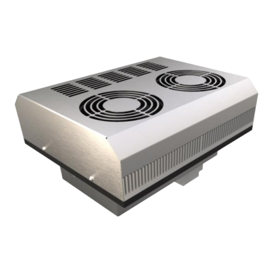
Wartung und Pflege Care and maintenance ......................... 13 Garantieerklärung Guarantee bond ..........................14 Abbildung auf der Titelseite zeigt Peltier-Kühlgerät PK 150-PS-C mit und ohne Aufbaugehäuse. Illustration on the title page shows Thermoelectric PK 150-PS-C cooler with and without additional housing. -
Page 3: Anwendung Application
The high efficiency contributes additionally to the eco-friendliness. With the integrated controller cooling and heating is possible. TECHNISCHE DATEN TECHNICAL DATA Bezeichnung Type PK 150-PS-C PK 150-PS-C-AG Artikelnummer Part number 40 P15 57HPSC 40 P15 57HPSCAG... -
Page 4: Beschreibung Description
Description Peltier-Kühlgerät 100 - 240 V AC, Kühlen und Heizen mit Regler TRP 205 PK 150-PS-C Thermoelectric cooler 100 - 240 V AC, cooling and heating with Controller TRP 205 Peltier-Kühlgerät 100 - 240 V AC, Kühlen und Heizen mit Regler TRP 205 und Aufbaugehäuse... -
Page 5: Lieferumfang Delivery Contents
For installation a cutout is necessary which can be done in door, side, or rear of the enclosure. Roof mounting is not possible with PK 150-PS-C(-AG). The mounting cutout must be according to the mounting position. The mounting position should be selected so that the air flow of the thermoelectric coolers supports the temperature control of the components. -
Page 6: Abmessungen Ohne Aufbaugehäuse Dimensions Without Additional Housing
CAD data of the cooling unit and the mounting cut- out can be downloaded from the website www.elmeko.de. To do this, enter the article number in the search field on the homepage and download the data on the device page under the Download section. -
Page 7: Abmessungen Mit Aufbaugehäuse Dimensions With Additional Housing
CAD data of the cooling unit and the mounting cut-out can be downloaded from the website www.elmeko.de. To do this, enter the article number in the search field on the homepage and download the data on the device page under the Download section. -
Page 8: Montageablauf Ohne Aufbaugehäuse Assembly Procedure Without Additional Housing
Remove the protective film of the sealing and put the cooler into the cut-out so that the heatsink, fans, connection socket and the threaded bolts protrude into the enclosure. PK 150-PS-C + KRP 300 PK 150-PS-C + KRP 300 Bei hoher Luftfeuchtigkeit und niedrigen Temperaturen im Schrankinneren Ansicht von innen: Das Kühlgerät mit... -
Page 9: Montageablauf Mit Aufbaugehäuse Assembly Procedure With Additional Housing
MONTAGEABLAUF MIT AUFBAUGEHÄUSE ASSEMBLY PROCEDURE WITH ADDITIONAL HOUSING Das Kühlgerät auf den Ausschnitt setzen. Montageausschnitt und Bohrungen nach Zeichnung anfertigen. Place the cooler on the cutout. Make mounting cut-out and drill holes according to drawing. Ansicht von innen: Das Kühlgerät mit Optimale Kühlung: Die warme Luft wird im Schaltschrank abgesaugt, sechs Linsenkopfschrauben M5x16 und im Kühlgerät abgekühlt und dann mit hoher Geschwindigkeit wieder... -
Page 10: Hinweise Zur Elektroinstallation Notes On Electrical Installation
HINWEISE ZUR ELEKTROINSTALLATION NOTES ON ELECTRICAL INSTALLATION Für den elektrischen Anschluss ist der Schaltschrank vorher vorschriftsmäßig außer Betrieb zu nehmen. Die Spannungsversorgung ist mit einem geeigneten Kabel an den mitgelieferten GST-Steckverbinder anzuschließen (siehe Schaltbild). Die Anschlussleitung wird dann mit der geräteseitigen GST-Buchse verbunden. Es wird eine Spannung von 100 - 240 V AC benötigt. -
Page 11: Regel- / Dauerbetrieb Innenlüfter Control / Continuous Mode Internal Fan
KLEMMENBELEGUNG TRP 205 TERMINAL CONNECTION TRP 205 Klemme Terminal Beschreibung Description Bedruckung Imprint Betriebsspannung (Masse) Supply voltage (ground) Betriebsspannung (+24V⎓) Supply voltage (+24V⎓) Anschluss Peltierelement (Masse) Peltier element connection (ground) Anschluss Peltierelement (+24V⎓) Peltier element connection (+24V⎓) Interner Temperatursensors Internal temperature sensor Hier keinen Schraubendreher ansetzen! Never use a screwdriver here! Anschluss für Brücke (bei Verwendung des internen Fühlers) - Page 12 REGLER TRP 205 CONTROLLER TRP 205 Der Regler verfügt über zwei Regelbereiche für die Funktionen Heizen und Kühlen. Im Einstellbereich mit dem -Symbol wird der Schaltpunkt für das Heizen festgelegt und im Einstellbereich mit dem Symbol wird der Schaltpunkt für das Kühlen festgelegt. Die Einstellbereiche sind durch eine Zone von 10 Kelvin getrennt. Somit wird eine Überschneidung der Schaltpunkte vermieden.
-
Page 13: Sicherheitshinweise Safety Instructions
SICHERHEITSHINWEISE SAFETY INSTRUCTIONS ▪ Die Installation darf nur von autorisiertem Fachpersonal vorgenommen werden. Die landesüblichen Richtlinien sind gemäß IEC 60364 einzuhalten ▪ Die technischen Daten auf dem Typenschild und in dieser Anleitung sind zu beachten ▪ Der Anschluss erfolgt an 100 - 240 V AC ▪... -
Page 14: Garantieerklärung Guarantee Bond
The repaired or replaced parts do not change the beginning or end of the warranty period Attention: Any tampering with the device will invalidate the warranty and result in the exclusion of liability! ELMEKO GmbH + Co. KG Graf-Zeppelin-Str. 5 56479 Liebenscheid Germany Tel. +49/2736/509748-0 info@elmeko.de www.elmeko.de...
Need help?
Do you have a question about the PK 150-PS-C and is the answer not in the manual?
Questions and answers