Sign In
Upload
Manuals
Brands
Tektronix Manuals
Test Equipment
82A04B
Tektronix 82A04B Manuals
Manuals and User Guides for Tektronix 82A04B. We have
2
Tektronix 82A04B manuals available for free PDF download: Service Manual, User Manual
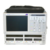
Tektronix 82A04B Service Manual (108 pages)
Digital Serial Analyzer, Sampling Modules
Brand:
Tektronix
| Category:
Measuring Instruments
| Size: 2.76 MB
Table of Contents
Table of Contents
5
Important Safety Information
9
General Safety Summary
9
Service Safety Summary
11
Terms in this Manual
12
Symbols and Terms on the Product
12
Compliance Information
13
Environmental Considerations
13
Preface
15
Related Documentation
16
Table I: Related Documentation
16
Operating Information
17
Windows Safe Mode
17
Where to Find User Information
17
Theory of Operation
19
Mainframe Overview
20
Figure 1: DSA8300 Block Diagram
20
Electrical Sampling Modules
22
Optical Sampling Modules
23
80A01 Trigger Prescale Preamplifier Module
25
80A02 EOS/ESD Protection Module
26
80A05 Electrical Clock Recovery Module
26
82A04B Phase Reference Module
27
Adjustment Procedures
29
Required Equipment
29
Equipment Hookup
30
Main Instrument Adjustments
30
Adjust DC Calibration
31
Verify DC Calibrator Adjustment
32
Internal 10 Mhz Adjust
33
Maintenance
35
Preventing ESD
35
Inspection and Cleaning
36
Removal and Installation
40
Required Equipment
40
Table 1: Required Equipment for Removal and Replacement
40
External Assemblies
41
Figure 2: External Assemblies
42
Line Fuses and AC Power Cord
43
Front-Panel Knobs
44
Figure 3: Knob Removal
44
Trim and Carrying Handle
45
Bottom Cover
46
Left and Right Covers
46
Internal Assemblies
47
Figure 4: Internal Assemblies
47
Front-Panel Assembly
48
Front Panel Board
49
Figure 5: J1 Flex Cable Connector Removal
49
Front Panel Keypad
50
Display Assembly
50
Display Adapter Board
52
Figure 6: Display Assembly Removal
52
Figure 7: Display Adaptor Board Removal
53
Standby/On Switch Flex Circuit
54
Figure 8: Display Adaptor Board Replacement
54
USB Assembly
55
Figure 9: USB Assembly Removal
55
Hard Disk Drive
56
DVD-RW Drive Assembly
57
Figure 10: Hard Disk Drive Removal
57
Figure 11: CD-RW/DVD Assembly Removal
58
CD/DVD-RW and Hard Disk Drive Mounting Frame
59
Figure 12: CD/DVD-RW Drive Removal
59
Figure 13: Hard Drive and CD-RW/DVD Drive Mounting Frame Removal
60
ATX Assembly
61
Figure 14: ATX Assembly Removal
62
Power PC Board
63
Figure 15: Power PC Board Removal
64
Power Side Board
65
Bridge Board
65
Fan Assembly
66
Figure 16: Fan Assembly Removal
67
Low-Voltage Power Supply
68
Electrical Sampling Modules
70
Figure 17: Sample of Electrical Module Hardware Removal
71
Optical Sampling Modules
72
80A00 and 82A00 Series Modules
73
Figure 18: 80A00 and 82A00 Series Module Disassembly
74
Troubleshooting
76
Check for Common Problems
76
Table 2: Possible Causes of Instrument Failure
76
Isolating Failures to the 80EXX/80CXX Modules or the Mainframe
79
Isolating to a Board if Power will Not Come up
80
Figure 19: Location of Debug Pins
80
Checking the Power Supply Voltages
81
PPC and ATX PC Diagnostics
82
BIOS Beep Codes
83
Table 3: BIOS Beep Codes
83
Firmware Updates
84
After Repair
84
Table 4: Action Required for Assembly Replaced
84
Reloading Instrument Model and Serial Number
85
Repackaging Instructions
86
Replaceable Parts List
87
Figure 20: External Parts
90
Table 5: External Replaceable Parts
91
Figure 21: Drives
92
Table 6: Drives Replaceable Parts
93
Figure 22: Front Panel and Processors
94
Table 7: Front Panel and Processors Replaceable Parts List
95
Figure 23: ATX Assembly
96
Table 8: ATX Assembly Replaceable Parts List
97
Figure 24: Front Panel Connectors
98
Table 9: Front Panel Connectors Replaceable Parts List
99
Figure 25: 80E01, 80E02, 80E03, and 80E04 Modules
100
Table 10: 80E01, 80E02, 80E03, and 80E04 Modules Replaceable Parts List
101
Figure 26: 80A05 Module (Option 10G Shown)
102
Table 11: 80A05 Module Replaceable Parts List
102
Figure 27: 80E06 Module
103
Table 12: 80E06 Module Replaceable Parts List
103
Figure 28: 80E07/B, 80E08/B, 80E09/B, and 80E10/B Modules
104
Table 13: 80E07/B, 80E08/B, 80E09/B, and 80E10/B Modules Replaceable Parts List
104
Figure 29: Optical Modules (All)
105
Table 14: 80C00 Optical Modules Replaceable Parts List (All Optical Modules)
105
Figure 30: 80A01 Module
106
Table 15: 80A01 Module Replaceable Parts List
106
Figure 31: 82A04B Module
107
Table 16: 82A04B Module Replaceable Parts List
107
Advertisement
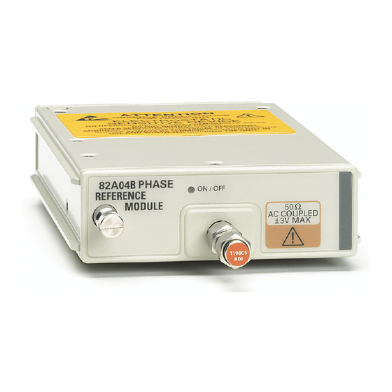
Tektronix 82A04B User Manual (23 pages)
Phase Reference Module
Brand:
Tektronix
| Category:
Test Equipment
| Size: 0.32 MB
Table of Contents
Table of Contents
7
Compliance Information
8
General Safety Summary
8
EMC Compliance
8
Environmental Considerations
9
Getting Started
11
Operating Basics
15
Specifications
19
Advertisement
Related Products
Tektronix 80A07
Tektronix 8 Series
Tektronix KEITHLEY 8010
Tektronix KEITHLEY 8010-DTB
Tektronix KEITHLEY 8009
Tektronix 834R01
Tektronix 82A00
Tektronix 80N01
Tektronix 8001A
Tektronix 8002A
Tektronix Categories
Test Equipment
Measuring Instruments
Amplifier
Printer
Portable Generator
More Tektronix Manuals
Login
Sign In
OR
Sign in with Facebook
Sign in with Google
Upload manual
Upload from disk
Upload from URL