Table of Contents
Advertisement
Thank you for choosing D5M series ,D6B series multi-function and high-performance inverter
produced by Zhejiang Dema Electric Co., Ltd.
Faulty operation of inverter during installation, wiring and operation may cause an accident,
please read the Instruction Manual carefully before using so as to master correct using
method, thus avoiding personal injury and property loss due to improper operation. After
reading, please keep the Instruction Manual well for future maintenance, protection and
application in other situations.
For your safety, please ask professional electrical engineering personnel to install and debug
the inverter and adjust the parameters.
Signs like
and
in the Manual remind you of precautions
when carrying, installing, operating and checking the inverter, please strictly follow the
labeled warnings to realize the safety in use.
Refer to the Manual in case of any doubts; for the problems unsolved, please contact the
Company directly or our distributors, we will assign professionals to serve you sincerely.
Version No.: 1.0
Date: February 10, 2012
Zhejiang Dema Electric Co., Ltd. is always dedicated to perfecting the products and
reserves the right to modify the Manual without notice.
Safety level in the Manual refers to "danger" and "warning" with the signs respectively as
below:
:Casualties may be caused if failing to use as required.
:Personal injury or damage to the inverter or mechanical system may
be caused if failing to use as required.
Make sure the contents with safety signs are observed. For different situations, "Warning"
may also cause serious results, so it is necessary to abide by the precautions in
Instruction Manual.
Advertisement
Table of Contents

Summary of Contents for DEMA D5M Series
- Page 1 Thank you for choosing D5M series ,D6B series multi-function and high-performance inverter produced by Zhejiang Dema Electric Co., Ltd. Faulty operation of inverter during installation, wiring and operation may cause an accident, please read the Instruction Manual carefully before using so as to master correct using method, thus avoiding personal injury and property loss due to improper operation.
- Page 2 ● Turn the power off before wiring. ● After cutting off AC power, high voltage still exists in the inverter before the charging indicator goes out, so it is dangerous to touch internal circuit and components. ● Don't check the components and signal on circuit board during operation. ●...
-
Page 3: Table Of Contents
1.3 Use ........................2 1.4 Storage ....................... 3 No.2 Product Introduction ....................4 2.1 Specification of D5M series ................. 4 2.2 General specification of the product ..............4 No.3 Wiring ........................7 3.1 Arrangement of main circuit terminals ..............7 3.2 Arrangement of control terminals ................. - Page 4 Table of Contents 6.1 Basic function parameters ................. 25 6.2 Application function parameters ................. 30 6.3 Functional parameter of input/output terminals ..........35 6.4 Functional parameter of analog quantity ............45 6.5 Functional parameters of multi-segment speed ..........48 6.6 Protection function parameters ................56 6.7 Function parameters of constant-pressure water supply ........
-
Page 5: 1 Safety Cautions
1. Inspection after unpacking (1) There is a Dema inverter, an instruction manual, a warranty card and a certificate of approval inside. (2) Check the nameplate at side of the inverter to make sure the product in hand is the right one. -
Page 6: Installation
NO.1 Safety Cautions 1.2 Installation ● Ambient temperature ranges from -5℃ to 40℃, high temperature and moist shall be prevented with the humidity less than 90% (non-condensation). ● Electromagnetic interference shall be prevented and interference source shall be kept away. ●... -
Page 7: Storage
NO.1 Safety Cautions ● It is prohibited to enable or disconnect motor unit during the running of inverter, so as to prevent overcurrent tripping even burning the main circuit. ● It is prohibited to remove the front cover of inverter during energizing to prevent electric shock causing personal injury. -
Page 8: 2 Product Introduction
NO.2 Product Introduction No.2 Product Introduction 2.1 Specification of D5M series Power Capacity of Output Applicable Model Input voltage (KW) driver (KVA) current (A) motor (KW) D5M-0.4S2-1A Single-phase 220V 50Hz D5M-0.75S2-1A Single-phase 220V 50Hz 0.75 0.75 D5M-1.5S2-1A Single-phase 220V 50Hz D5M-2.2S2-1A... - Page 9 NO.2 Product Introduction status, fault, etc. Communication control RS-485 Operating temperature -10~40℃ Relative humidity ranging from 0 to 95% (without Humidity condensation) Vibration Below 0.5G Range 0.10-400.00Hz Digital type: 0.01% (-10-40℃); analog type: 0.1% Accuracy (25± 10℃) Digital type: 0.01Hz; analog type: 1% of the Setting resolution maximum operating frequency Output resolution...
- Page 10 NO.2 Product Introduction Electric relay protection motor driver (constant Overload protection torque: 150% per minute, fans: 120% per minute). FUSE protection In case of fuse, the motor stops running 220V: DC voltage>390V 380V: DC Over voltage voltage>800V 220V: DC voltage<200V 380V: DC Low voltage voltage<400V...
-
Page 11: 3 Wiring
NO.3 Wiring No.3 Wiring 3.1 Arrangement of main circuit terminals [Note] Screws on main control board serve as PE terminals for that of 0.4-1.5kW. 3.2 Arrangement of control terminals 3.3 Description of main circuit terminals Symbol of Name of terminal Description terminal Connected... -
Page 12: Description Of Control Terminals
NO.3 Wiring 3.4 Description of control terminals Symbol of Function of terminal Description terminal Set as forward during delivery Set as reverse during delivery Set as reset during delivery Multi-function digital input terminals 1-6 Set as high speed during delivery Set as medium speed during delivery Set as low speed during delivery Digital/analog/communication... - Page 13 NO.3 Wiring [Note] NPN type wiring mode shall be adopted in case of P067=0. Figure 3-1 NPN Type Wiring Mode (2) When PNP type wiring mode is adopted for external equipment, source-type logic is induced, and the current flows into from input terminal (sinking current) as shown in Figure 3-2, at the same time parameter P067=1 is required.
-
Page 14: Basic Wiring Diagram
Figure 3-3 below refers to standard wiring diagram of ex-factory D5M series. Figure 3-3 Standard Wiring of D5M series ,D6B series Inverter... - Page 15 NO.3 Wiring 1. Main circuit wiring ● During wiring, please select wire diameter specification and conduct wiring as per those specified by electrical engineering laws so as to ensure the safety. ● For power supply wiring, prefer shielded wire or spool, and earth isolating layer or both ends of spool.
-
Page 16: 4 Manipulator Description
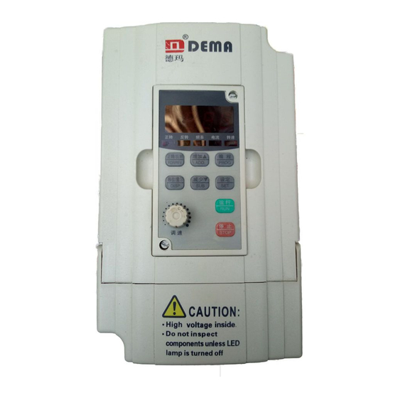
NO.4 Manipulator Description No.4 Manipulator Description 4.1 Description of operation panel appearance and key function Figure 4-1 D5M Series Digital Manipulator [Note] Two switching modes of forward and reverse rotation are provided for D5M: 1) Press and hold down the key FOR/REV;... -
Page 17: Description Of Displayed Items
NO.4 Manipulator Description 4.3 Description of displayed items Displayed content Description Output frequency is 50.0Hz at this time Set frequency is 50.0Hz Output current is 3.0A at this time Output speed is 1440r/min and speed light turns on at this time DC voltage is 510V at this time AC voltage is 380V at this time Inverter temperature is 35.0℃... -
Page 18: 5 Function List
NO.5 Function List No.5 Function List Description of special symbols: * indicates that this parameter content has various set values or it shall be specifically set based on actual situation. Ex-factory value refers to parameter value set during delivery of inverter or parameter value refreshed while the user restores ex-factory operation. -
Page 19: Application Function Parameters
NO.5 Function List limit P012 Reserve ╳ P013 Parameter resetting 8 restore ex-factory value ○ P014 Acceleration time I 0.1-6500.0s ○ P015 Deceleration time I 0.1-6500.0s ○ P016 Acceleration time II 0.1-6500.0s ○ P017 Deceleration time II 0.1-6500.0s ○ P018 Acceleration time III 0.1-6500.0s ○... -
Page 20: Functional Parameters Of Input/Output Terminals
NO.5 Function List ○ P042 Jogging frequency 0.00-400.00 Hz 5.00 ○ P043 S curve time 0.0-6500.0s 5.3 Functional parameters of input/output terminals Function Ex-factory Function name Setting range and data content Alteration code value ╳ P044 FOR(X1) function 0: Invalid 1: Run 2: Forward 3: Reverse 4: Stop ╳... - Page 21 NO.5 Function List 4: DC braking indication 5: Setting frequency arrival indication 6: Accelerating indication 7: Decelerating indication Frequency consistency arrival I indication Frequency consistency arrival II indication 10: Motor overload indication 11: Over-torque indication 12: Inverter overload indication Pulse setting counter arrival indication...
-
Page 22: Functional Parameters Of Analog Quantity
NO.5 Function List 31: Actuation indication of electromagnetic relay 32: Fan actuation indication ○ P054 AO output function Analog voltage output 0-3 ○ P055 AO analog output gain 0-100% ○ P056 Hopping frequency 1 0.00-400.00Hz 0.00 ○ P057 Hopping frequency 2 0.00-400.00Hz 0.00 ○... -
Page 23: Functional Parameters Of Multi-Segment Speed
NO.5 Function List Bias direction of 0: Positive ╳ P075 low-end frequency 1: Negative Selectable negative 0: Irreversible ╳ P076 bias reverse of analog 1: Reversible quantity UP.DOWN memory 0: Not memorized ╳ P077 function selection 1: Memorized UP.DOWN increment ╳... - Page 24 NO.5 Function List Speed operation directions of last ╳ P083 0-255(0: Forward 1: Reverse) internally controlled 8 segments Acceleration/decelerati on time of the first ╳ P084 0-65535s internally controlled 8 segments Acceleration/deceleration time of the last internally ╳ P085 0-65535s controlled 8 segments P086 Frequency II setting...
-
Page 25: Protection Function Parameters
NO.5 Function List P115 Internally controlled multi-segment speed timer XV 0.0-6500.0s P116 Internally controlled multi-segment speed timer XVI 0.0-6500.0s Internally controlled multi-segment speed memory ╳ P117 function 5.6 Protection function parameters Function Setting range and Ex-factory Function Alteration code function description value ╳... -
Page 26: Motor Function Parameters
NO.5 Function List pump ○ P133 High-speed operating time 1-250s ○ P134 Low-speed operating time 1-250s ○ P135 Stop pressure level 1-150% ○ P136 Stop level continuous time 1-250s ○ P137 Wake-up level 1-150% ○ P138 Sleep frequency 0.00-400.0Hz 20.00 Continuous time of sleep ○... -
Page 27: Communication Function Parameters
P164 speed P165 Communication data mode P166-P168 Reserve 0: Standard Modbus Selection of communication Agreement ╳ P169 protocol 1: Dema communication protocol 5.11 Monitoring function parameters Function Setting range and content Ex-factory Function Alteration code description value Selection of display P170 ○... - Page 28 NO.5 Function List —— P180 Unexpected error 4 △ P181 Software version No. 00-02 P182-P250 Reserve...
-
Page 29: 6 Detailed Function Descriptions
NO.6 Detailed Function Description No.6 Detailed Function Descriptions 6.1 Basic function parameters P000 Setting range Unit Ex-factory value Change ╳ Parameter locking 0: Invalid 1: Valid i.e. parameter locking, meaning other parameters are unchangeable except this parameter. This parameter can avoid mistake operation of non-operators which may cause unnecessary danger and mistake. - Page 30 NO.6 Detailed Function Description In case that frequency option is set by keyboard, the frequency operates with set value of P003. During operating, the current operating frequency can be changed with keys ▲ and ▼. In multi-segment operation, main frequency is taken as frequency I. If P002 is set as 1, i.e. the external analog quantity is set, the frequency I is set by analog quantity of external terminals.
- Page 31 NO.6 Detailed Function Description [Note] The ex-factory value of 220V grade inverter is 15 while that of 380V grade is 28. This parameter can set intermediate voltage values in any V/F curve. Improper setting may cause motor overcurrent or insufficient torque and even inverter tripping. Augmenting intermediate voltage may augment the output torque and the output current will increase at the same time.
- Page 32 NO.6 Detailed Function Description characteristics. P011 Setting range Unit Ex-factory value Alteration ○ Lower limit of frequency 0.00-400.00 0.01 Hz 0.00 The purpose of lower limit of frequency is to prevent misoperation of site personnel and avoid overheat or other mechanical fault due to too low running frequency of motor. The setting of lower limit of frequency must be smaller than the setting value of upper limit of frequency.
- Page 33 Refer to t2 in Figure 6-2 for details. Figure 6-2 Acceleration/deceleration Time Curves D5M series ,D6B series of inverters define four kinds of acceleration/deceleration time in all from acceleration/deceleration I to IV. Users can select different acceleration/deceleration time through the corresponding function switching of acceleration/deceleration time at external switch terminals as required;...
-
Page 34: Application Function Parameters
NO.6 Detailed Function Description 6.2 Application function parameters P023 Setting range Unit Ex-factory value Alteration ╳ Reverse prohibit 0: Reverse prohibit 1: Reverse valid This parameter setting is applied to sites where motor is irreversible so as to avoid misoperation of operators. When reverse is prohibited, motor can only rotate in a forward way rather than in a reverse way. - Page 35 NO.6 Detailed Function Description frequency tracking downward and carry out tracking at the maximum speed. During starting, the current may be relatively large and overcurrent or stalling phenomenon may occur. It is necessary to pay attention to the adjustment of tracking current level. P033 is generally set at about 100 and shall be specifically set as per the mechanical inertia.
- Page 36 NO.6 Detailed Function Description DC braking startup is usually used when load can move under ventilation status for motor will be in free running status with uncertain direction before inverter outputs voltage. Therefore, we can execute DC braking before startup and then start the motor to avoid the tripping of motor.
- Page 37 NO.6 Detailed Function Description P033 Setting range Unit Ex-factory value Alteration Frequency tracking current ╳ 0-200% level When inverter is executing frequency tracking, output current shall take this set value as level. When output current is larger than this level, the frequency will drop and make current below current level, and then re-execute the frequency tracking.
- Page 38 NO.6 Detailed Function Description Ex-factory Alteratio P042 Setting range Unit value 0.01H ○ Jog frequency 0.00-400.00Hz 5.00 This parameter can realize the jog function in machine testing and jog operation only can be realized through 6-way programmable terminals. Jog frequency is limited by maximum operation frequency and lower frequency limit.
-
Page 39: Functional Parameter Of Input/Output Terminals
NO.6 Detailed Function Description 6.3 Functional parameter of input/output terminals P044 Setting range Unit Ex-factory value Alteration X1 terminal function P045 X2 terminal function P046 X3 terminal function ╳ P047 00-32 X4 terminal function P048 X5 terminal function P049 X6 terminal function 01: RUN refers to running, and can form several control mode in combination with other terminals. - Page 40 NO.6 Detailed Function Description 12: In case radiator or motor is overheating, this contact shall be used for detection to protect motor and inverter. 13: Emergency cut-off may receive external fault signals such as emergency stop. 14: Reset can be used after fault elimination. 15-16: Reserve 17: Acceleration/deceleration time selection I 18: Acceleration/deceleration time selection II...
- Page 41 NO.6 Detailed Function Description ◆ Three-wire connection Three multi-functional terminals shall be used for three-wire connection to enable switching between forward and reverse rotating, which is widely used for optoelectronic switch and other cases, as shown in Figure 6-7. (1) Button description B1: Forward Button (normally open), with effective edge B2: Reverse Button (normally open), with effective edge B3: Stop Button (normally closed), with effective edge...
- Page 42 NO.6 Detailed Function Description X4 terminal X5 terminal Result Acceleration/deceleration time I Acceleration/deceleration time II Acceleration/deceleration time III Acceleration/deceleration time IV [Description] 1) This function is enabled when P080 is set as 0, 2 and 3 and disabled upon disturbed and internally controlled multi-segment speed; 2) Four selections of acceleration/deceleration are available with combination of any two multi-function input terminals;...
- Page 43 NO.6 Detailed Function Description Frequency remains the same [Description] 1) UP and DOWN functions are only enabled when the frequency source is under keyboard operation, i.e. P002 is 0. 2) UP and DOWN functions are effective during running and the frequency cannot be changed during standby.
- Page 44 NO.6 Detailed Function Description P053 Output function of terminals FA, FB and FC 01: Indications during Contact is enabled in case of output or running indication running from inverter. 02: Zero-speed indication Contact is enabled if output frequency is less than start-up frequency.
- Page 45 NO.6 Detailed Function Description 17: Low voltage warning Contact is enabled if low voltage is detected by the indication inverter. 18: Stage completion Contact is enabled and one pulse is output after each indication for internally stage is completed under programming operation of the controlled multi-segment inverter.
- Page 46 NO.6 Detailed Function Description 0-maximum operation frequency 1: 0-10V analog quantity output, corresponding to output current, 0-10V corresponding to 0-two times of rated current of the inverter 2: Analog quantity output, corresponding to DC bus voltage, 0-10V corresponding to 0-1000V 3: Analog quantity output, corresponding to output AC voltage, 0-10V corresponding to 0-510V/255V [Note] Three-phase 380V model is corresponding to 510V and single-phase 220V...
- Page 47 NO.6 Detailed Function Description Setting P060 Unit Ex-factory value Alteration range Frequency consistency I 0.00-400.00 P061 0.01Hz 0.00 Frequency consistency II ○ P062 0.10-10.00 0.01Hz 0.50 Frequency consistency range When output frequency is more than consistent frequency, corresponding multi-functional output terminal is enabled, with consistent frequency range as a hysteresis loop. When the inverter is used for constant-pressure water supply, P060 is used as high-speed frequency and P061 is set as low-speed frequency.
- Page 48 NO.6 Detailed Function Description PNP, with P067 set as 1. P068-P069 Reserve...
-
Page 49: Functional Parameter Of Analog Quantity
NO.6 Detailed Function Description 6.4 Functional parameter of analog quantity P070 Setting range Unit Ex-factory value Alteration Input channel selection ╳ for analog quantity There are two channels Al1 and Al2 and three modes to be selected for analog quantity input: [Channel 1] 0: 0-10V 1: 0-5V [Channel 2] 2: 0-20mA/0-10V 3: 4-20mA/2-10V... - Page 50 NO.6 Detailed Function Description 0: Positive direction 1: Negative direction Bias direction refers to forward/reverse command instruction; positive bias represents forward and negative bias symbolizes reverse. Refer to diagram description of P076 for details. P076 Setting range Unit Ex-factory value Alteration Reverse selection for ╳...
- Page 51 NO.6 Detailed Function Description (4) Parameters: P073=10 P075=1 P072=40 P074=0 P076=0 [Description] This curve is an extended one of the above curve. 2V-10V (4.8mA-20mA) is corresponding to 0Hz-40Hz and signals of 0V-2V (4-4.8mA) are invalid. The curve can be used to avoid noise disturbance. Under severe environment, signals under 1V shall not be used as far as possible to set operating frequency of the inverter.
-
Page 52: Functional Parameters Of Multi-Segment Speed
NO.6 Detailed Function Description 6.5 Functional parameters of multi-segment speed P080 Setting range Unit Ex-factory value Alteration ╳ Operation mode selection 0: Common operation refers to operation in a commonly controlled way. 1: Internally controlled multi-segment speed (16-segment speed) [Description] 1) 16-segment speed is composed by main speed and 15-segment speed;... - Page 53 NO.6 Detailed Function Description For multi-segment speed VI, the frequency is determined by P090 For multi-segment speed VII, the frequency is determined by P091 For multi-segment speed VIII, the frequency is determined by P092 For multi-segment speed IX, the frequency is determined by P093 For multi-segment speed X, the frequency is determined by P094...
- Page 54 NO.6 Detailed Function Description Figure 6-12. Figure 6-12 Daft Actuation Curve [Description] 1) Draft will be actuated upon triggering of the external multi-function terminal. 2) During draft actuation, running time T is P101×10. 3) After the completion of draft actuation, the inverter outputs at a constant speed (P087), and corresponding multi-function output contacts are actuated until the stop command is issued, and then, the inverter stops running, and multi-function output contact resets.
- Page 55 NO.6 Detailed Function Description 2) Circular running: the inverter runs in sequence and circularly at the set value of internal parameters for segment speed frequency and running time; any command input, except stop, external fault, and emergency stop in the circular running, is not accepted.
- Page 56 NO.6 Detailed Function Description selection for first 8 segments P085 ╳ Acceleration/deceleration time selection for last 8 segments This parameter set is only effective when P080 is set as 1. The setting methods of acceleration/deceleration time for internally controlled multi-stage speed and segment speed are as follows: (1) Acceleration/deceleration time is determined by binary 2bit Bit1...
- Page 57 NO.6 Detailed Function Description P085 is a selection for the acceleration/deceleration time of last 8 segments (calculation method is the same as that for P084). P086 Setting Range Unit Ex-factory Value Alteration Frequency II setting P087 Frequency III setting P088 Frequency IV setting P089 Frequency V setting...
- Page 58 NO.6 Detailed Function Description P101 Setting Range Unit Ex-factory Value Alteration Timer I 10.0 P102 10.0 Timer II P103 Timer III P104 Timer IV P105 Timer V P106 Timer VI P107 Timer VII P108 Timer VIII ○ P109 0.0-6500.0s 0.1s Timer IX P110 Timer X...
- Page 59 NO.6 Detailed Function Description P117 Setting Range Unit Ex-factory Value Alteration Memory function for ╳ internally controlled multi-segment speed 0: Not memorized 1: Memorized This parameter determines the pause function during inverter control at internally controlled multi-segment speed; when P117=1, it can memorize the inverter operating state, and can even memorize during stop or failure, then continue to run after back to normal;...
-
Page 60: Protection Function Parameters
NO.6 Detailed Function Description 6.6 Protection function parameters Ex-factory P118 Setting range Unit Alteration value Selection of overvoltage stall ╳ prevention 0: Overvoltage stall prevention function is invalid 1: Overvoltage stall prevention function is valid During inverter deceleration, the motor shall produce rebound energy into inverter under the influence of load inertia to make the voltage on inverter DC side rise;... - Page 61 NO.6 Detailed Function Description ╳ Stall level during deceleration 0-200% Please refer to P120 description. P123 Setting range Unit Ex-factory value Alteration Selection of over torque ╳ detection method 0: While achieving the frequency, start to detect over torque; after the detection of over torque, continue operating.
- Page 62 NO.6 Detailed Function Description P127 – P129 Reserve...
-
Page 63: Function Parameters Of Constant-Pressure Water Supply
NO.6 Detailed Function Description 6.7 Function parameters of constant-pressure water supply P130 Setting range Unit Ex-factory value Alteration ╳ Number of auxiliary pumps The quantity of auxiliary pumps shall be set via this parameter; start or stop of auxiliary pumps are realized by using multi-function output contact, and auxiliary pump 1 or 2 shall be controlled through peripheral control circuit. - Page 64 NO.6 Detailed Function Description Figure 6-15 High/Low-speed Operating Time Curve of Pump P134 Setting range Unit Ex-factory value Alteration ○ Low-speed operating time 1-250s During the application of constant pressure water supply, when main pump frequency operates at low speed (set via P061) due to reduction of water consumption and low-speed operating time (P134) is achieved, corresponding multi-function contact shall be actuated and auxiliary pumps stop.
- Page 65 NO.6 Detailed Function Description Figure 6-16 for details. Sleep frequency refers to the minimum operating frequency while going sleep; refer to Figure 6-16 for details. Sleep frequency continuous time refers to continuous time of operating under sleep frequency; refer to Figure 6-16 for details. P140 Reserve Figure 6-16 Main Pump State Setting and Time Curve...
-
Page 66: Motor Function Parameters
NO.6 Detailed Function Description 6.8 Motor function parameters P141 Setting range Unit Ex-factory value Alteration ╳ Rated voltage of motor 0.1V It shall be set as per rated voltage value on motor nameplate; ex-factory value of 230V grade inverter and that of 440V grade inverter are respectively 220 and 380. P142 Setting range Unit... - Page 67 NO.6 Detailed Function Description The setting of motor no-load current shall affect the quantity of slip compensation and rated current of the motor is 100%. P147 Setting range Unit Ex-factory value Alteration ╳ Motor slip compensation 0.-1.0 0.000 When the inverter drives the motor, both the load and the slippage shall increase, and motor running speed shall be closer to synchronous speed via slip compensation and slippage reduction.
- Page 68 NO.6 Detailed Function Description P154 Setting range Unit Ex-factory value Alteration ╳ Allowable outage duration 0.1-5.0s 0.1s The maximum duration of outage can be determined via this parameter; in case of going beyond set time, the inverter shall still stop outputting after power recovery; restart shall proceed as per general startup sequence.
-
Page 69: Pid Function Parameters
NO.6 Detailed Function Description 6.9 PID function parameters P156 Setting range Unit Ex-factory value Alteration ○ Proportional constant (P) 0.0-1000.0% 0.1% 100.0 Error value gain is set for proportional constant; in case of I=0 and D=0, only proportional control shall be actuated. P157 Setting range Unit... - Page 70 NO.6 Detailed Function Description Figure 6-18 PID Control Block Diagram Figure 6-19 Suppress Output Figure 6-20 Suppress Output Oscillation of PID Exceeding of PID Control Control (1) Suppress output exceeding (2) Suppress output oscillation a: Decrease derivation time (D value) a: Decrease derivation time (D value) or set it as 0 b: Extend integration time (I value) b: Decrease proportionality constant (P value)
-
Page 71: Communication Function Parameters
NO.6 Detailed Function Description 6.10 Communication function parameters P163 Setting range Unit Ex-factory value Alteration ╳ Communication address 0-250 When RS-485 communication port control is set for the inverter, the position of each inverter shall be set via a parameter. 0: No communication function 01-250: Position of inverter P164... - Page 72 NO.6 Detailed Function Description selection 0: Standard Modbus protocol 1: Dema communication protocol Dema communication protocol is default; in case of applying standard Modbus protocol, please contact the manufacturer. Format of Dema communication protocol (I) Two modes of communication protocol RTU mode: Each 8bit data is composed of two hexadecimal characters of 4bit, for example: 64H (hex).
- Page 73 NO.6 Detailed Function Description CRC: Error detection value RTU mode, adopting CRC (cyclical Redundancy Check) error detection value; CRC value is obtained via C language below, and thus function requires two parameters: unsigned char data index of message buffer unsigned char length number of bytes in message buffer This function shall send back CRC value in the form of unsigned integer.
- Page 74 NO.6 Detailed Function Description Secondary reverse compensation of CDH is 34H, so transmitted data content is: 3AH 30H 31H 30H 32H 30H 33H 30H 33H 30H 42H 42H 38H 33H 34H 0DH 0AH 4. End bit RTU mode ends in a manner of mute (>50ms) and ASCII ends in a manner of CR(0DH)LF(0AH).
- Page 75 NO.6 Detailed Function Description mode Reception [Note] When the maximum parameter value of function code is less than (256) FFH, data length is 02H. For example, function code P029 (1DH) shall be set as 1.0s (0AH), for maximum value of P029 is 25.0s (FAH) and less than FFH, at this time data length LEN=02H and data content DATA is 1DH 0AH.
- Page 76 NO.6 Detailed Function Description in binary, each bit indicates different operating states of the inverter. The meaning of each Bit of CNST is as follows: Bit of CNST Operation state Bit7 Frequency tracking Bit6 In braking Bit5 In forward/reverse rotation Bit4 In jogging Bit3...
- Page 77 NO.6 Detailed Function Description [Example] Set frequency 30.00Hz Data format Start Check Communication code >50 Transmission >50ms BF 8E mode >50 Reception >50ms BF 8E Transmission ASCII mode Reception [Note] ASCII Table Character symbol ASCII Character symbol ASCII...
-
Page 78: Monitoring Function Parameters
NO.6 Detailed Function Description 6.11 Monitoring function parameters P170 Setting range Unit Ex-factory value Alteration Selection of displayed ○ content This parameter is set to select PID feedback value and other contents to display, thus in favor of monitoring by the user, and the contents is displayed one by one through switching key;... - Page 79 NO.6 Detailed Function Description P175 Setting range Unit Ex-factory value Alteration Inverter type 0: Constant torque 1: Fans Read-only parameter, alteration inapplicable. P176 Setting range Unit Ex-factory value Alteration Standard for inverter frequency 0:50Hz 1:60Hz The value set in factory, read-only parameter, monitoring applicable and alteration inapplicable.
-
Page 80: 7 Maintenance And Fault Information
NO.7 Maintenance and Fault Information NO.7 Maintenance and Fault Information Regular maintenance and inspection during the application shall make your inverter in normal condition for long period. 7.1 Maintenance and inspection cautions 1 Be sure to first cut off power supply of inverter (L1. L2. L3) during maintenance and inspection. -
Page 81: Fault Information And Fault Clearing
NO.7 Maintenance and Fault Information 7.3 Fault information and fault clearing Inverters of D5M feature more perfect protection function in terms of overload, interphase short circuit, earthing short circuit, undervoltage, overheating and overcurrent, etc. In case of occurrence of inverter protection, ascertain the cause as per the information shown below. After handling, perform the running operation newly;... -
Page 82: Fault And Analysis
NO.7 Maintenance and Fault Information Variable frequency low 1: Inspect network voltage; 2: Send for repair. voltage 1: Inspect whether the fan is locked and radiating fin is free of foreign matter; 2: Whether ambient temperature is normal; Inverter overheating 3: Whether there is air space enough for air convection;... - Page 83 NO.7 Maintenance and Fault Information (5) The inverter is in fault protection condition. (6) Fault of motor or inverter. 2. Parameter setting failure (1) Password is locked; conduct setting after decoding. (2) The inverter is operating. (3) Abnormal connection of connector assemblies and abnormal communication of digital actuator;...
-
Page 84: Common Anomalies And Countermeasures
NO.7 Maintenance and Fault Information (2) DC braking during starting has been set, and it is required to increase DC braking value. 9. Vibration or roaring of the machine (1) For resonance of vibration frequency of mechanical system and carrier wave, adjust carrier wave to avoid resonance point. - Page 85 NO.7 Maintenance and Fault Information Improper setting of acceleration/deceleration time. Unfavorable Too low current limit is set. acceleration/deceleration of Overvoltage protection during deceleration. motor Improper setting of carrier frequency, overloading or oscillation. Improper selection of V/F characteristic. Improper selection of reference for V/F characteristic and resetting shall be performed.
-
Page 86: 8 Selection And Configuration Of Peripheral Facilities
NO.8 Selection and Configuration of Peripheral Facilities No.8 Selection and Configuration of Peripheral Facilities 8.1 Options Name Function Protect the connection of inverter, be sure to set breaker Breaker and leakage switch on power side, and please use the leakage switch with for connection higher harmonic prevention Set electromagnetic contactor to prevent burning out... -
Page 87: Configuration
NO.8 Selection and Configuration of Peripheral Facilities 8.2 Configuration 1. AC reactor configuration Model Matched power (W) Rated current (A) Inductance (mH) 0.75 220V 0.71 0.75 380V 0.52 0.397 18.5 0.352 Line reactor, through which alternating current flows, is also called commutation reactor and applied to network incoming line and it is used for suppressing inverter harmonic and feedbacking to the network. - Page 88 NO.8 Selection and Configuration of Peripheral Facilities 2. Brake resistor configuration Specification of brake Brake torque Dedicated motor resistor Model of inverter 10%ED Ω D5M-0.4T2-1A D5M-0.75T2-1A 0.75 D5M-1.5T2-1A D5M-2.2T2-1A D5M-3.7T2-1A D5M-5.5T2-1A D5M-0.4T4-1A D5M-0.75T4-1A 0.75 D5M-1.5T4-1A D5M-2.2T4-1A D5M-3.7T4-1A D5M- 5.5T4-1A D5M-7.5T4-1A 1000 D5M-11T4-1A 1000...
-
Page 89: Annex
Annex Annex Annex I Examples of Simple Application 1. Disturbance function (triangular wave achievement) Figure F-1 Disturbance Function Curve (1) Achieve those shown in F-1 curve. (2) Parameter setting P080=5 P003=30 P086=27 P092=0.5 P101=10 P102=10 2. Realization of drafting function As shown in the curve of Figure F-2. - Page 90 Annex As shown in the curve of Figure F-3. Parameter setting P001=1 P002=1 P072=50 P073=50 P074=0 P075=1 P076=1 Figure F-3 Motor Forward/Reverse Curve and Wiring Diagram 4. Internally controlled 8-segment speed operation Realize those shown in the curve of Figure F-4 and stop internally controlled 8-segment speed after operating by one cycle.
- Page 91 Annex 5. Simple constant-pressure water supply (1) Use pressure transmitter with the range of 0-10kg and feedback of 4-20mA; pressure water supply of 5kg as required, alarm while above upper limit of 6kg and below lower limit of 4kg, and stop starting external terminal. As shown in Figure F-5. Parameter setting P001=1 P041=5...
- Page 92 P158=* P160=1 [Note] 1) Target value of D5M series inverter can be selected through two methods, one referring setting via panel and the other one referring to 0-10V analog ; 2) Feedback signal is 4-20mA and the others are invalid;...
- Page 93 Annex (3) Wiring diagram and parameters of single-machine and multi-pump are shown in Figure F-7. Parameter setting P001=1 P014=* P015=* P023=0 P026=1 P041=* P045=25 P046=04 P053=8 P060=* P130=1 P156=* P157=* P158=* P159=* Figure F-7 Single-machine and Multi-pump Wiring Diagram 6. Cases of joint application of analog and multi-segment speed Requirements: Set the frequency of the first segment speed via analog;...
- Page 94 Annex Figure F-8 Analog and Multi-segment Joint Application Wiring Diagram [Description] Multi-function terminal can be used for reverse switching and the panel for forward/reverse switching (in this case, switching via panel). K1 state K2 state Operating frequency Set via potentiometer Segment-speed II (15Hz) Segment-speed III (30Hz) Segment-speed IV (25Hz)
-
Page 95: Annex Ii External And Installation Dimensions
Annex Annex II External and Installation Dimensions 1. External dimension of machine with power of 0.4-2.2kW D5M-0.4S2-1A D5M-0.75S2-1A D5M-1.5S2-1A Name D5M-0.75T4-1A D5M-1.5T4-1A D5M-2.2T4-1A External installati dimensi Unit: mm... - Page 96 Annex 2. External dimension of machine with power of 2.2-7.5kW D5M-2 2S2-1A D5M-3.7S2-1A Name D5M-3.7T4-1A D5M-5.5T4-1A D5M-7.5T4-1A External installati dimensi Unit: mm...
- Page 97 Annex 3. External dimension of machine with power of 11-18.5kW Name D5M-11T4-1A D5M-15T4-1A D5M-18.5T4-1A External installati dimensi Unit: mm...
-
Page 98: Warranty And Services
Warranty and Services Warranty and Services The products of our company are of "Quality Commitment"; in case of any quality problem, please contact the dealer or corporate headquarters. Our company shall provide a full range of solutions for the users in combination with specific circumstances as per the rules below, and the users are requested to carefully read them. - Page 99 Both the sellers and agencies of our company in China are authorized to provide after-sale services for the products of our company.
Need help?
Do you have a question about the D5M Series and is the answer not in the manual?
Questions and answers