Table of Contents
Advertisement
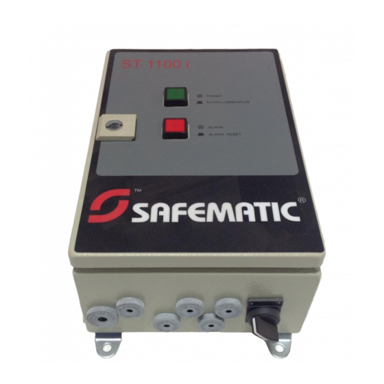
CONTROL CENTER ST-1100i
TABLE OF CONTENTS
1 GENERAL DESCRIPTION ................................................................................................................................1
2 DESIGN .............................................................................................................................................................1
2.1 Cover...........................................................................................................................................................1
2.1.1 LED-signals ..........................................................................................................................................1
2.1.2 Buttons .................................................................................................................................................1
2.2 Control Panel...............................................................................................................................................2
2.2.1 General.................................................................................................................................................2
2.2.2 Display..................................................................................................................................................2
2.2.3 Buttons .................................................................................................................................................2
2.2.4 LED-signals ..........................................................................................................................................3
3 OPERATION......................................................................................................................................................4
3.1 Normal mode...............................................................................................................................................4
3.1.1 Phase codes for normal mode and alarm mode...................................................................................4
3.1.2 Normal mode displays ..........................................................................................................................5
3.1.3 Line pressure displays..........................................................................................................................6
3.1.4 Returning to normal mode ....................................................................................................................6
3.2 Extra lubrication...........................................................................................................................................7
3.3 Manual control.............................................................................................................................................7
3.4 Lubrication cycle counter ............................................................................................................................8
3.5 Power failure ...............................................................................................................................................8
3.6 Alarms .........................................................................................................................................................9
3.6.1 Low limit alarm......................................................................................................................................9
3.6.2 Pressure alarm .....................................................................................................................................9
3.6.3 Power failure alarm...............................................................................................................................9
3.6.4 Electronic system error alarm.............................................................................................................10
4 SETTINGS .......................................................................................................................................................10
4.1 General......................................................................................................................................................10
4.2 Entering settings........................................................................................................................................10
4.3 Entering password ....................................................................................................................................11
4.4 Setting mode .............................................................................................................................................11
4.4.1 Lubrication cycle counter....................................................................................................................11
4.4.2 Lubrication cycle.................................................................................................................................12
4.4.3 Maximum pressurization time .............................................................................................................12
4.4.4 Pressurization delay time coefficient ..................................................................................................12
110i1CEN.doc
SAFEGREASE, SAFEOIL
ST-1100i
16.04.2003 Rev. 1C
Advertisement
Table of Contents

Summary of Contents for SAFEMATIC ST-1100i
-
Page 1: Table Of Contents
SAFEGREASE, SAFEOIL ST-1100i CONTROL CENTER ST-1100i TABLE OF CONTENTS 1 GENERAL DESCRIPTION ..........................1 2 DESIGN ................................1 2.1 Cover................................1 2.1.1 LED-signals ............................1 2.1.2 Buttons ..............................1 2.2 Control Panel...............................2 2.2.1 General..............................2 2.2.2 Display..............................2 2.2.3 Buttons ..............................2 2.2.4 LED-signals ............................3 3 OPERATION..............................4 3.1 Normal mode...............................4 3.1.1 Phase codes for normal mode and alarm mode...................4... - Page 2 SAFEGREASE, SAFEOIL ST-1100i 4.4.5 Low and high pressure limits ......................12 5 TECHNICAL SPECIFICATIONS ........................13 5.1 Technical data ............................13 5.2 Connections ..............................14 5.3 Symbols..............................14 6 SPARE PARTS..............................14 2 APPENDICES 110i1CEN.doc 16.04.2003 Rev. 1C...
-
Page 3: General Description
Numbers in brackets refer to part numbers in the drawing 461543A. ST-1100i Control Center main switch is located (pos. 1) at the bottom edge of the center casing. There is a green power supply LED-signal (pos. 2) which is also the extra lubrication start button. -
Page 4: Control Panel
2 (14) SAFEGREASE, SAFEOIL ST-1100i 2.2 Control Panel 2.2.1 General Control panel is located inside the casing. Control panel has a 6-character display, three buttons and the input/output LED signals. The display and buttons can be used for setting the default values for lubrication program and for turning on manual control. -
Page 5: Led-Signals
3 (14) SAFEGREASE, SAFEOIL ST-1100i 2.2.4 LED-signals Signal Description PRESSURE, LINE 1 Line 1 pressure control status In pressure switch operation, the signal is lit, when the switch is closed. In pressure transmitter operation, the signal is lit when pressure exceeds the set high level and is turned off, when the pressure goes below the set low limit. -
Page 6: Operation
4 (14) SAFEGREASE, SAFEOIL ST-1100i 3 OPERATION 3.1 Normal mode 3.1.1 Phase codes for normal mode and alarm mode When control center is in normal or alarm mode, the phase code corresponding to the program phase is shown on the value display. -
Page 7: Normal Mode Displays
5 (14) SAFEGREASE, SAFEOIL ST-1100i Pressure discharge In pressure transmitter operation, line pressure discharge is measured and new pressurization can be started only after pressure in all lines is below the set low limit value. When center is waiting for pressure discharge completion, there is a phase dC in the value display and time display shows the spent discharge time. -
Page 8: Line Pressure Displays
6 (14) SAFEGREASE, SAFEOIL ST-1100i Configuration settings Note Configuration settings should be changed only in connection to system changes. These changes are usually implemented by the supplier. Configuration mode requires a password. Table 1. Center operation modes Time display code... -
Page 9: Extra Lubrication
7 (14) SAFEGREASE, SAFEOIL ST-1100i 3.2 Extra lubrication Extra lubrication can be launched by pressing the Extra lubrication button located on the cover Led signal Power. Lubrication is launched, if the center is not currently pressurizing the system, in alarm mode or turned off. -
Page 10: Lubrication Cycle Counter
8 (14) SAFEGREASE, SAFEOIL ST-1100i Manual operation Connect line 1 or 2 line control by means of L1 or L2 function Start pump by means of PU-S or PU-F function. Program does not start the pump, unless line control is connected. Time display shows pumping time. -
Page 11: Alarms
9 (14) SAFEGREASE, SAFEOIL ST-1100i 3.6 Alarms The center is in alarm mode, when the red Alarm signal is lit. 3.6.1 Low limit alarm The center triggers a low limit alarm, pauses pressurization and goes into alarm mode, if the lubricant container is empty which means that the low limit switch is closed. -
Page 12: Electronic System Error Alarm
10 (14) SAFEGREASE, SAFEOIL ST-1100i 3.6.4 Electronic system error alarm The center triggers an electronic system error alarm and goes into alarm mode, if the test program ran at the start-up detects any errors in the electronic system. The value display shows phase code AE and time display the spent alarm time. -
Page 13: Entering Password
11 (14) SAFEGREASE, SAFEOIL ST-1100i 4.3 Entering password Select code PASS at time display. Enter correct password using Settings/Pressure and arrow buttons. When Settings/Pressure button is released, the center goes into Setting mode. The codes show now decimal points, for example C.C. -
Page 14: Lubrication Cycle
12 (14) SAFEGREASE, SAFEOIL ST-1100i 4.4.2 Lubrication cycle Code L.C. shows the lubrication cycle set value at display. Enter desired lubrication cycle value using Settings/Pressure and arrow buttons. The time can be set within 0 min 00 s -9999 min. In grease lubrication systems, pumping is started twice during one cycle. -
Page 15: Technical Specifications
13 (14) SAFEGREASE, SAFEOIL ST-1100i 5 TECHNICAL SPECIFICATIONS 5.1 Technical data Value Range Unit Description -20…+60 °C operation temperature 230 ±15%, 50/60 V AC, Hz Power input, 160 VA max. 115 ±15%, 50/60 V AC, Hz Voltage range preset at factory and indicated in the center name plate. -
Page 16: Connections
Portuguese language, Norwegian language, Dutch no symbol power input, 230 V AC ±15% 50/60 Hz power input, 115 V AC ±15% 50/60 Hz 6 SPARE PARTS See ST-1100i control center spare parts (drawing no. 461544A) 110i1CEN.doc 16.04.2003 Rev. 1C...
Need help?
Do you have a question about the ST-1100i and is the answer not in the manual?
Questions and answers