
Related Manuals for schmersal AZM300Z-I2-ST-1P2P-N-DU


Summary of Contents for schmersal AZM300Z-I2-ST-1P2P-N-DU
-
Page 1: Table Of Contents
INSTRUCTIONS FOR OPERATION AND ASSEMBLY SOLENOID INTERLOCK AZM300Z-I2-ST- 1P2P-N-DU Table of Contents 1 About this document 1.1 Function 1.2 Target group of the operating instructions: authorised qualified personnel 1.3 Explanation of the symbols used 1.4 Appropriate use 1.5 General safety instructions 2 Product description 2.1 Ordering code 2.2 Special versions... -
Page 2: About This Document
Caution:Failure to comply with this warning notice could lead to failures or malfunctions. Warning:Failure to comply with this warning notice could lead to physical injury and/or damage to the machine. 1.4 Appropriate use Products in Schmersal's range are not intended to be used by private end consumers. -
Page 3: General Safety Instructions
The user must observe the safety instructions in this operating instructions manual, the country specific installation standards as well as all prevailing safety regulations and accident prevention rules. Further technical information can be found in the Schmersal catalogues or in the online catalogue on the Internet: products.schmersal.com. -
Page 4: Special Versions
without Power to unlock Power to lock without Manual release Emergency release Emergency exit Emergency exit, distance 8.5 mm 2.2 Special versions For special versions, which are not listed in the ordering code, these specifications apply accordingly, provided that they correspond to the standard version. 2.3 Purpose The non-contact, electronic safety switchgear is designed for application in safety circuits and is used for monitoring the position and locking of movable safety guards. -
Page 5: Warning About Misuse
The user must evaluate and design the safety chain in accordance with the relevant standards and the required safety level. If multiple safety sensors are involved in the same safety function, the PFH values of the individual components must be added. The entire concept of the control system, in which the safety component is integrated, must be validated to the relevant standards. - Page 6 Frequency band RFID 125 kHz Transmitter output RFID, maximum -6 dB/m Enclosure material Plastic, glass-fibre reinforced thermoplastic, self-extinguishing Time to readiness, maximum 5,000 ms Duration of risk, maximum 200 ms Reaction time, switching off safety outputs via actuator, maximum 100 ms Reaction time, switching off safety outputs via safety inputs, 1.5 ms maximum...
- Page 7 Performance Level, up to Category PFH value 2.00 x 10⁻⁹ /h PFD value 1.80 x 10⁻⁴ Safety Integrity Level (SIL), suitable for applications in Mission time 20 Year(s) Mechanical data Mechanical life, minimum 1,000,000 Operations Note (Mechanical life) When using as door stop: ≥ 50.000 operations (door mass ≤ 5 kg and actuating speed ≤...
- Page 8 Length of sensor 146 mm Width of sensor 87.5 mm Height of sensor 55 mm Ambient conditions Degree of protection IP67 IP69 IP66 Ambient temperature, minimum +0 °C Ambient temperature, maximum +60 °C Storage and transport temperature, minimum -10 °C Storage and transport temperature, maximum +90 °C Relative humidity, maximum...
- Page 9 Switching frequency, maximum 0.5 Hz Electrical data - Magnet control Designation, Magnet control Switching thresholds -3 V … 5 V (Low) 15 V … 30 V (High) Current consumption at 24V 10 mA Magnet switch-on time 100 % Test pulse duration, maximum 5 ms Test pulse interval, minimum 40 ms...
- Page 10 Test pulse interval, typical 1000 ms Classification ZVEI CB24I, Source Classification ZVEI CB24I, Sink Electrical data - Diagnostic outputs Designation, Diagnostic outputs Voltage drop U , maximum Voltage, Utilisation category DC-12 24 VDC Current, Utilisation category DC-12 0.05 A Voltage, Utilisation category DC-13 24 VDC Current, Utilisation category DC-13 0.05 A...
-
Page 11: Mounting
This device complies with the nerve stimulation limits (ISED SPR-002) when operated at a minimum distance of 100 mm. Changes or adjustments not expressly approved by K.A. Schmersal GmbH & Co. KG could void the user's authority to operate the equipment. - Page 12 The solenoid interlock can be used as an end stop. Dependant upon the door weight and the actuating speed, the mechanical life could be reduced. Mounting of the solenoid interlock and the actuator Refer to the mounting instructions manual for the corresponding actuator. The actuator must be permanently fitted to the safety guards and protected against displacement by suitable measures (tamperproof screws, gluing, drilling of the screw heads).
- Page 13 The diagrams show a closed guard system with a set latching force of 50 N (see also chapter "adjustment of latching force"). Provide for a sufficient insertion of the actuator into the rotary handle. Correct False To avoid any interference inherent to this kind of system and any reduction of the switching distances, please observe the following guidelines: The presence of metal chips in the vicinity of the solenoid interlock is liable to modify the switching distance Keep away from metal chips...
-
Page 14: Manual Release
The minimum distance from metallic securing surfaces to the face side "A" and underside "B" of the device is 5 mm. 3.2 Manual release For the machine set-up, the solenoid interlock can be unlocked in a de-energised condition. The solenoid interlock is unlocked by turning the manual release in the position The normal locking function is only restored after the manual release has been returned to its original position... -
Page 15: Emergency Exit -T/-T8 Or Emergency Release -N
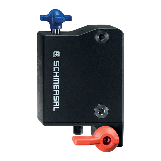
Caution: do not turn beyond the end stop! A: connector plug M12, 8-pole B: LED display C1: Manual release by means of slotted screwdriver C2: Manual release by means of triangular key TK-M5 The manual release must be protected against accidental actuation, e.g. by using the enclosed seal after completing commissioning. -
Page 16: Mounting With Mounting Plate
Reset of the manual release by actuating the red emergency exit lever must be prevented by the user. Emergency exit (-T/-T8) (fitting and actuation only from within the hazardous area) To activate the emergency exit, turn the red lever in the direction of the arrow to the end stop. The safety outputs switch off and the guard system can be opened. -
Page 17: Dimensions
3.5 Dimensions All measurements in mm. AZM300...-T/-T8 and -N Device with emergency exit or emergency release Emergency exit -T / Emergency release -N... -
Page 18: Actuator And Accessories
Emergency exit -T8 3.6 Actuator and accessories Actuator AZ/AZM300-B1 (not included in delivery) Mounting plate MP-AZ/AZM300-1 (available as accessory) - Page 19 MS-AZ/AZM300-B1-1 (available as accessory) Aluminium protective plate as a cover for use on glass and plastic doors on machines with high design requirements Lockout tag SZ 200-1 (available as accessory)
-
Page 20: Electrical Connection
Bowden cable release ACC-AZM300-BOW-.-.M-.M (available as accessory) Observe the additional notes in the operating instructions of the Bowden cable release. 4 Electrical connection 4.1 General information for electrical connection The electrical connection may only be carried out by authorised personnel in a de-energised condition. The voltage inputs A1, X1, X2 and IN must have a protection against permanent overvoltage. -
Page 21: Serial Diagnostic -Sd
Information for the selection of suitable safety-monitoring modules can be found in the Schmersal catalogues or in the online catalogue on the Internet: products.schmersal.com. -
Page 22: Wiring Configuration And Connector Accessories
Y1 and Y2 = Safety outputs → Safety monitoring module Wiring example 2: Series-wiring of the AZM300 with serial diagnostic function (max. 31 components in series) In devices with the serial diagnostics function (ordering suffix -SD), the serial diagnostics connections are wired in series and connected to a SD-Gateway for evaluation purposes. -
Page 23: Actuator Coding And Latching Force Adjustment
Function safety switchgear Pin configuration of Colour codes of the Poss. colour code of other the connector Schmersal connectors commercially available connectors according to EN 60947-5-2 With conventional With serial IP67 / IP69 IP69 diagnostic output diagnostic to DIN... -
Page 24: Latching Force Adjustment
Individually coded solenoid interlocks and actuators will require the following "teach-in" procedure: 1. Switch the solenoid interlock's voltage supply off and back on. 2. Introduce the actuator in the detection range. The teach-in procedure is signalled at the solenoid interlock, green LED off, red LED on, yellow LED flashes (1 Hz). -
Page 25: Diagnostic-Leds
In the standard AZM300Z variant, the unlocking of the solenoid interlock causes the safety outputs to be disabled. The unlocked safety guard can be relocked as long as the actuator is inserted in the AZM300Z solenoid interlock; in that case, the safety outputs are re-enabled. It is not necessary to open the safety guard. - Page 26 Normal sequence, door was locked Door could not be locked or fault Legend Safety guard open Safety guard closed Locking time Safety guard not locked or fault Safety guard locked Lock Unlock ...
- Page 27 Power to lock: IN = 1 = Lock Safety guard can be locked Safety guard locked Table 1: Diagnostic information of the safety switchgear Safety outputs Y1, Diagnostic Magnet control IN output OUT System condition Power to Power to green yellow...
-
Page 28: Solenoid Interlock With Serial Diagnostic Function Sd
In this way, the diagnostic signals can be evaluated by means of a PLC. The necessary software for the integration of the SD-Gateway is available for download at products.schmersal.com. The response data and the diagnostic data are automatically and permanently written in an input byte of the PLC for each solenoid interlock in the series-wired chain. -
Page 29: Set-Up And Maintenance
Diagnostic error (warning) If an error (warning) is signalled in the response byte, detailed fault information can be read out. Table 3: I/O data and diagnostic data (The described condition is reached, when Bit = 1) Bit n° Call Byte Response-Byte Diagnostic error warning Diagnostic error... -
Page 30: Disassembly And Disposal
Adequate measures must be taken to ensure protection against tampering either to prevent tampering of the safety guard, for instance by means of replacement actuators. Damaged or defective components must be replaced. 8 Disassembly and disposal 8.1 Disassembly The safety switchgear must be disassembled in a de-energised condition only. 8.2 Disposal The safety switchgear must be disposed of in an appropriate manner in accordance with the national prescriptions and legislations.
Need help?
Do you have a question about the AZM300Z-I2-ST-1P2P-N-DU and is the answer not in the manual?
Questions and answers