Table of Contents
Advertisement
Quick Links
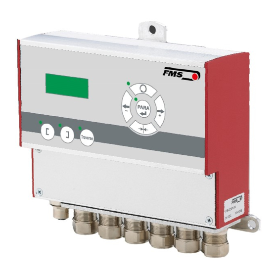
Operating Manual BKS309.W.M
Digital Web Guide Controller with Integrated Functions for
Motorized Traverse
Document version
1.30 08/2018 NS
Firmware Version
V2.43
Diese Bedienungsanleitung ist auch in Deutsch erhältlich.
Bitte kontaktieren Sie Ihren nächstgelegenen FMS Vertreter.
© by FMS Force Measuring Systems AG, CH-8154 Oberglatt – All rights reserved.
Advertisement
Table of Contents

Related Manuals for FMS BKS309.W.M


Summary of Contents for FMS BKS309.W.M
- Page 1 Digital Web Guide Controller with Integrated Functions for Motorized Traverse Document version 1.30 08/2018 NS Firmware Version V2.43 Diese Bedienungsanleitung ist auch in Deutsch erhältlich. Bitte kontaktieren Sie Ihren nächstgelegenen FMS Vertreter. © by FMS Force Measuring Systems AG, CH-8154 Oberglatt – All rights reserved.
-
Page 2: Table Of Contents
Operating Manual BKS309.W.M Inhalt TARGET GROUPS ........................3 SAFETY INSTRUCTIONS ......................3 ESCRIPTION ONDITIONS ..........................3 IST OF AFETY NSTRUCTIONS .......................... 4 SYSTEM AND FUNCTIONAL DESCRIPTION ................5 INSTALLATION AND WIRING ....................6 – FMS MASTER ................6 NSTALLATION OF THE STEERING FRAME –... -
Page 3: Target Groups
Operating Manual BKS309.W.M 1 Target Groups This manual addresses mechanics who will install and connect the single components and operators who will setup the machine and put it into operation. The following skills are required as per target group. Mechanics (installation, assembly) Knowledge of electrical and measuring techniques, basic mechanical skills (drilling, thread cutting, fastening technology, occupational health and safety. -
Page 4: List Of Safety Instructions
Some contacts on the pc board are supplied with a power of 230V! Mortal danger! Disconnect the power supply before you open the housing! Proper function of the FMS web guide is only guaranteed with the recommended application of the components. In case of other arrangement, heavy malfunction can be the result. -
Page 5: System And Functional Description
By means of the electric drives of the traverses, the sensor positon can be adjusted via the control panel. The BKS309.W.M controller can be used in combination with steering frames of the type webMASTER, with steering roller of the type webDIRECTOR and with actuators of the type winderGLIDE. -
Page 6: Installation And Wiring
Therefore, the installation instructions on the following pages must strictly be followed. 4.1 Installation of the steering frame – FMS webMASTER The mounting orientation of the steering frame (indicated by an arrow), must correspond with the direction of the moving web. The lower frame part is mounted with four M8 screws to the machine frame. -
Page 7: Installation Of The Actuator - Fms Winderglide
Attach the housing of the actuator to the machine frame. Bolt the moving part (connection rod) to the winding roll. Different connectors (fork head, yoke, etc.) are available from the FMS accessories program. Dimensions can be taken from the data sheet. -
Page 8: Installation Of The Sensors
Operating Manual BKS309.W.M 4.4 Installation of the sensors The matching installation brackets for the sensors can be ordered from our accessories program. Dimensions of the sensors can be taken from the data sheet. Please follow the instructions in the installation manual of the respective material sensor. -
Page 9: Connecting Terminal
Operating Manual BKS309.W.M 4.6 Connecting Terminal The connections are located underneath a cover plate on the front side of the controller. The plate can be lifted after removing the 4 screws. Illustration 4: Access to the connection termal Note First connect the wires of the lower connection terminal (connection 1-15 and 41- Illustration 5: Connecting terminal BKS_309.ai... -
Page 10: Electrical Connection Of Material Sensors
4.8 Connecting FMS winderGLIDEs BKS.D.3, BKS.D.4 or a steering frame FMS webMASTER BKS030 Illustration 6:Pin assignment of FMS winderGLIDEs BKS.D.3 and BKS.D.4 and terminal blocks of controller. The illustration shows a BKS.D.3 or BKS.D.4. The wiring of the BKS030 is similar. - Page 11 Operating Manual BKS309.W.M Illustration 7: Wiring diagram for BKS020.EE and BKS015.EE BKS_309.ai Illustration 8: Wiring diagram for BKS.D.6 BKS_309.ai 22.02.2019...
-
Page 12: Operation
Operating Manual BKS309.W.M 5 Operation 5.1 Operating Panel Automatic or manual LED operation mode mode Enter, select Traverse control Drive/increase value/scroll parameter Edge guiding (right) or line guiding Move to center point Edge guiding (left) or Drive/decrease line guiding value/scroll parameter... -
Page 13: Menu Levels
Operating Manual BKS309.W.M 5.3 Menu levels The functions and parameters of the controller are arranged in three different menus. Menu 1 – system parameters Menu 2 – operating parameters Menu 3 – traverse parameters and functions A complete list of all parameters is printed on page 23. -
Page 14: Initial Start-Up And Basic Settings
Steering frames of the FMS webMASTER and webDIRECTOR series are detected automatically o Actuators of the FMS winderGLIDE series have to be configured manually. You have to enter the mounting position of the actuator. • Quantity and type of the applied motorized traverses •... - Page 15 Operating Manual BKS309.W.M If you have installed an actuator of the FMS winderGLIDE series, you have to set the below parameter as well: WinderGLIDE – system parameter Function Enter the menu for changing the system parameters > 3 Sec Scroll through the list of parameters to the menu point [WinderGL] Changing the parameter: the selected parameter name starts flashing.
-
Page 16: Basic Functions Of The Controller
Operating Manual BKS309.W.M 6 Basic functions of the controller 6.1 Automatic mode In the automatic mode the controller leads the web along the reference value and keeps it there. Edge guiding (left or right side) Reference value (on the LCD "ʌ") = center of sensor range Center guiding (2 sensors installed) Reference value (on the LCD "ʌ") = center position of the 2 sensor axis... -
Page 17: Manual Mode
Operating Manual BKS309.W.M Leave the menu for changing the traverse parameters. The LED above the key is now off. The LED is off as you leave the automatic mode. Note If the web is not moving the system may not be able to lead the web to the reference value! The actuator possibly reaches its limit stops and may cause damage to the web. -
Page 18: Selection Of The Guiding Logics
Operating Manual BKS309.W.M Function Press both keys. The LED is on. The LCD indicates the actual position of the actuator. Approach the desired position. After pressing briefly the LED stars flashing. The position can now be stored. Stores the actual position as [Home Pos]... -
Page 19: Basic Functions Of The Motorized Traverse In Manual Mode
Operating Manual BKS309.W.M 7 Basic functions of the motorized traverse in manual mode 7.1 Retract the sensors [Retract] Select this function to move the sensors away from the web. Function Switch to manual mode. The LED is off Enter the menu for changing the traverse parameters. The LED is on. - Page 20 Operating Manual BKS309.W.M Illustration 13: Zero point set outside the Illustration 14: Zero point set in the web, e.g. on the machine frame center of the web, in between the traverses. Absolute zero point Web and direction of travel Home position of each traverse Left traverse, sensor left "Sens R/l"...
-
Page 21: Repositioning The Traverses Manually
Operating Manual BKS309.W.M Switch to manual mode. The LED is off Enter the menu for changing the traverse parameters. The LED is on. Scroll through the list of parameters to the menu point [SetZerPL] for left sensor or [SetZerPR] for right sensor After pressing briefly the LED starts flashing. - Page 22 Operating Manual BKS309.W.M Drive the sensor to the desired position. Confirming the selection will store the value Re-positioning a single sensor – Reference to other sensor Scroll through the list of parameters to the menu point [Sens L] for left sensor or [Sens R] for right sensor.
-
Page 23: Operating Parameters
Operating Manual BKS309.W.M 8 Operating parameters Adjusting the offset [Ref Pos] Description: the is stored as long the controller is connected to the power supply. Range: -5.00 to +5.00 Default: 0.00 Increment 0.01 unit: [mm] Origin of the reference value [Ref Mode]... - Page 24 Operating Manual BKS309.W.M Set relay outputs 1 and 2 [Relay 1] und [Relay 2] Description: This parameter sets the function behind the relay outputs. Setting: Middle position found [MidSenso] Description: the relay is activated as soon as the web edge is detected in center the sensor area.
- Page 25 Operating Manual BKS309.W.M Description: The controller switches from manual to automatic mode or vice versa. Setting: Move actuator to center position [Centre] Description: This input triggers the movement of the actuator to the center position. (Default for Input 2).This input is level controlled Setting: Decrease reference value or drive to left [-Ref/ ←]...
- Page 26 Operating Manual BKS309.W.M Description: A rising edge on the input triggers this function and the stored position point is approached. Setting: [Disabled] Description: This function disables the selected input. Setting: Move traverse to right [MoveTvR] Description: This level controlled function triggers the movement of the connected traverse to the right.
- Page 27 Operating Manual BKS309.W.M Setting: [Yes] Description: Password protection enabled. [Sprache] [Language] Description: Choose the desired language on the display. Setting: [English] Description: default Setting: [Deutsch] LCD-contrast [Contrast] Description: to achieve the maximum legibility you can change this value depending on the location, illumination, etc.
- Page 28 Default: Increment: unit: [ mm] Requirement: This parameter is only accessible if an actuator of the FMS winderGLIDE series is installed. Center position of the actuator [CentrPos] Description: This parameter determines the center position of the actuator. If you press the actuator approaches this position automatically.
- Page 29 Alignment of the actuator [Actuator] Description: This parameter is important for the control logic and determines the moving directions of the actuator. Requirement: This parameter is only accessible if an actuator of the FMS winderGLIDE series is installed. Setting: [Left] Description: The actuator is mounted on the left side of the winding/unwinding station in reference to the moving direction of the web.
- Page 30 Operating Manual BKS309.W.M Direction of positive movement [LegthInc] Description: This parameter determines the direction to which the displayed value will increase. Setting: [Left] Description: The value increases as the sensor moves to the left. Setting: [Right] Description: The value increases as the sensor moves to the right.
- Page 31 Operating Manual BKS309.W.M [Subnet] Description: This parameter defines the IP address of the controller. This is the basic requirement for a communication via web browser. You have to enter the subnet mask address in 4 separate blocks. (Sub. Bl 1 to 4).
-
Page 32: System Parameters
Warning All system parameters have been pre-set individually per system. These settings should only be changed in compliance with the FMS Service. Non-authorized changes can lead to malfunctions and cause damage to the system or the machine. To enter the mode for changing the system parameters you have to press the keys at the same time and hold it for 3 sec. - Page 33 [Reverse] Description: Select this setting if you have installed a motor with reverse direction of rotation. If you have installed an actuator of the FMS winderGLIDE series this parameter is automatically set by the controller. Type of actuator [WinderGL] Description: This parameter defines the type of FMS winderGLIDE that you have installed.
-
Page 34: Traverse Parameters And Functions
Description: Maximum stroke of 300mm (11.81in). Warning for BKS.D.4 If you are using an FMS winderGLIDE BKS.D.4 you have to select the parameter for the BKS.D.3 with the corresponding stroke of 125 or 200mm. 10 Traverse parameters and functions Retract the sensors from the web [Retract] Description: This function will automatically retract all configured traverses. -
Page 35: Restore Default Settings
Operating Manual BKS309.W.M Manually moving a single sensor, display of relative dimensions [Sens L] and[Sens R] Description: This function will move the selected sensor. The display will show the distance from one sensor to the other sensor. If you have not set a zero point the indicated value refers to the home position of the selected sensor. -
Page 36: Setup For Connection To A Pc Or Network
Operating Manual BKS309.W.M Alternatively, you can press simultaneously press during the start-up (apply supply voltage) of the controller. The display will show "Reset to Default". After a reset you have to trigger the [RefRun] within the menu for the traverse parameters. -
Page 37: Connection Via Web Browser
Operating Manual BKS309.W.M Illustration 16: connection to a PC 12.1 Connection via web browser Make sure that you have assigned an IP address in a static block to your PC. As soon as you integrated the controller into a network you can access it via its default address. - Page 38 Operating Manual BKS309.W.M Illustration 18: Virtual operating panel 22.02.2019...
- Page 39 Operating Manual BKS309.W.M Illustration 19: List of parameters Illustration 20: Traverse settings 22.02.2019...
- Page 40 Operating Manual BKS309.W.M Illustration 21: Traverse types Illustration 22: Ethernet settings 22.02.2019...
-
Page 41: Setting Up A Peer-To-Peer Connection With A Pc
Operating Manual BKS309.W.M Illustration 23: Firmware version 12.2 Setting up a peer-to-peer connection with a PC Make sure that you have assigned an IP address in a static block to your PC. If you have already connected the controller to a network you can skip the following steps. - Page 42 Operating Manual BKS309.W.M Illustration 24: Status of the LAN connection Illustration 25: Status of the LAN connection 6. Select "Properties" 7. Window "properties of LAN connection" will open. 8. Select "Internet protocol Version 4 (TCP/IPv4) ". 9. Click on "properties"...
- Page 43 2. The default IP address of the controller is set to 192.168.000.090. Enter this address into the search field of your browser and press enter. Enter the address in the following format: 192.168.0.90. 3. The screen "BKS309.W.M-Home" will open. Refer to page XXX. 22.02.2019...
-
Page 44: Trouble-Shooting
Operating Manual BKS309.W.M 13 Trouble-shooting Error Cause Solution Web edge outside The edge has moved Re-adjust the sensor to the edge. sensor detection outside the sensor Check adjustment of the reference area detection area. value Too big adjustment of the reference... - Page 45 Operating Manual BKS309.W.M Error Cause Solution Display and menu Wrong configuration Adjust operating parameter [Traverse] does only offer the of traverses selection of one traverse/sensor, but 2 are connected 22.02.2019...
-
Page 46: Dimensions
Operating Manual BKS309.W.M 14 Dimensions Illustration 27: Dimensions of the housing in mm and in. 15 Technical Data Cycle time processor 1 ms Drive Stepper motor, threaded spindle Analog inputs 2 inputs 0...10 V (for sensors) Digital inputs 4 inputs, 24 VDC electrically isolated Relay outputs 2 outputs. - Page 47 Operating Manual BKS309.W.M 22.02.2019...
- Page 48 Operating Manual BKS309.W.M FMS Force Measuring FMS USA, Inc. FMS (UK) FMS (Italy) Systems AG 2155 Stonington Avenue Aspstrasse 6 Aspstrasse 6 Aspstrasse 6 Suite 119 8154 Oberglatt 8154 Oberglatt (Switzerland) 8154 Oberglatt (Switzerland) Hoffman Estates,, IL 60169 (Switzerland) Tel. +39 02 39487035 Tel.
Need help?
Do you have a question about the BKS309.W.M and is the answer not in the manual?
Questions and answers