Table of Contents
Advertisement
Quick Links
Advertisement
Table of Contents

Related Manuals for JCM VEGA Series


Summary of Contents for JCM VEGA Series
- Page 1 Support: http://www.jcmglobal.com/en/contact/default.aspx Web-Site: http://www.jcmglobal.com VEGA Series ™ BankNote Validator Operation and Maintenance Manual (Revision A) P/N 960-100189RA_Rev. A {EDP #148850} Issue #4064-SME-01-00 © 2009, Japan CashMachine Co., Limited...
- Page 2 2. When an end user duplicates the Manual to maintain operation of the product or operate the product in general. JCM retains all rights to amend, alter, change or delete any portion of this Manual in whole, or in part, or add items ...
-
Page 3: Table Of Contents
VEGA Bezel Outside Dimensions (Type SH) ................1-12 VEGA Bezel Outside Dimensions (Type N) ................1-13 VEGA Bezel Outside Dimensions (Type D) ................1-13 JCM Contact Information ..................1-14 Americas & Oceania........................1-14 JCM American Corporation ........................1-14 Europe, Africa, Russia & Middle East ..................1-14 JCM Europe GmbH ..........................1-14... - Page 4 JCM American Corporation........................3-1 Europe, Africa, Russia & Middle East ..................3-1 JCM Europe GmbH..........................3-1 UK & Ireland ..........................3-1 JCM United Kingdom Ltd........................3-1 Asia ............................3-1 JCM Gold (HK) Ltd..........................3-1 Japan Cash Machine Co, Limited (HQ) ....................3-1 4 DISSASSEMBLY/REASSEMBLY................
- Page 5 VEGA™ Series BankNote Validator Table of Contents Page Activation Failure ........................6-10 Adjustment Failure ........................6-10 Adjustment Data Writing Failure ....................6-11 Menu Item Functions ....................6-11 Writing a Serial Number......................6-12 Reading a Serial Number ....................... 6-12 Reading ccTalk Encryption Code .................... 6-12 Reading the ccTalk Address ....................
- Page 6 JCM American Corporation........................A-8 Europe, Africa, Russia & Middle East ..................A-8 JCM Europe GmbH..........................A-8 UK & Ireland ..........................A-8 JCM United Kingdom Ltd........................A-8 Asia ............................A-8 JCM Gold (HK) Ltd..........................A-8 Japan Cash Machine Co, Limited (HQ) ....................A-8 B GLOSSARY ......................
- Page 7 VEGA™ Series BankNote Validator List of Figures Page Figure 1-1 VEGA Unit Assembly ................1-1 Figure 1-2 Precautionary Symbols ................1-2 Figure 1-3 Unacceptable Banknotes ............... 1-3 Figure 1-4 VEGA Component Names ..............1-4 Figure 1-5 VEGA System Configuration with Host destination example ....1-5 Figure 1-6 VEGA Banknote Validator Unit Outside Dimensions ...
- Page 8 VEGA™ Series BankNote Validator List of Figures Page Figure 2-17 VEGA Banknote Validator Operational Flowchart (Part 1 Full Process).2-8 Figure 2-18 VEGA Banknote Validator Operational Flowchart (Part 2 Stack) ...2-9 Figure 2-19 VEGA Banknote Validator Operational Flowchart (Part 3 Reject) ..2-10 Figure 4-1 Cash Box &...
- Page 9 VEGA™ Series BankNote Validator List of Figures Page Figure 6-12 Download Progress Screen..............6-3 Figure 6-13 Completed Screen.................. 6-4 Figure 6-14 Reference Paper Types ................. 6-4 Figure 6-15 PC Calibration Tools & Cabling.............. 6-5 Figure 6-16 Non-PC Calibration Tools & Cabling ............6-5 Figure 6-17 Opening VEGA For Paper Placement............
- Page 10 VEGA™ Series BankNote Validator List of Figures Page Figure 6-56 Retrying Calibration Message Screen ..........6-10 Figure 6-57 Calibration Failed Message Screen ............6-10 Figure 6-58 Error “Save As” PC Screen..............6-10 Figure 6-59 Duplicate File Name Confirmation ............6-11 Figure 6-60 EEPROM Write Error Screen..............6-11 Figure 6-61 Retrying Writing Message Screen ............6-11 Figure 6-62 Data Writing Failure Screen..............6-11 Figure 6-63 Menu Bar Pull-Down Selections 1 ............6-12...
- Page 11 VEGA™ Series BankNote Validator List of Tables Page Table 1-1 Model Number Specifications ..............1-2 Table 1-2 VEGA System Configuration List.............. 1-5 Table 1-3 VEGA Technical Specification..............1-6 Table 1-4 VEGA Environmental Specification ............1-6 Table 1-5 VEGA Electrical Specification..............1-7 Table 1-6 VEGA Structural Specification ..............
- Page 12 VEGA™ Series BankNote Validator List of Tables THIS PAGE INTENTIONALLY LEFT BLANK P/N 960-100189RA_Rev. A {EDP #148850} © 2009, Japan CashMachine Co., Limited...
-
Page 13: General Information
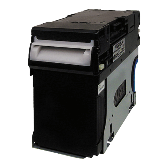
VEGA™ Series BankNote Validator S e c t i o n 1 1 GENERAL INFORMATION This section provides a general overview of the In order to make operation of this device easier and VEGA BankNote Validatior pictured in Figure 1-1. make navigation within this manual simpler, the This first section is designed to help you navigate following illustrations were used within the text:... -
Page 14: Model/Type Number Specifications
Section 1 VEGA™ Series BankNote Validator General Information Model/Type Number Specifications The Figure 1-2 symbols are defined as follows: 1. (Type 1) Do not insert a torn, folded, or wet Ban- Table 1-1: Model Number Specifications knotes, as this action may cause a Banknote jam inside the unit. -
Page 15: Cash Box Handling
General Information VEGA™ Series BankNote Validator Section 1 Unacceptable Banknotes 2. If the Banknote Validation Section is dirty due to dust, foreign objects or other such debris adher- The following Banknote types may not validate ing to it, Banknote acceptance rate will degrade. correctly, or can cause a Banknote jam and/or dam- Clean the VEGA Unit once a month to keep its age to the Unit’s Transport path. -
Page 16: Primary Features
Section 1 VEGA™ Series BankNote Validator General Information Primary Features of target Host Machines by changing the Face- plate and the Cash Box Stop location. The VEGA contains the following primary 2. A single denomination can flow in reverse by features: adding the optional VEGA-RC Unit. -
Page 17: System Configurations
General Information VEGA™ Series BankNote Validator Section 1 System Configurations Figure 1-5 illustrates a typical VEGA system configuration. Figure 1-5 VEGA System Configuration with Host destination example Table 1-2: VEGA System Configuration List Part Item VEGA Unit PC (Windows 2000/XP) Power Supply (e.g., UAC, MIB232, etc.) Host Machine (e.g., Game Machine, Vending Machine etc.) Interface Connector (VEGA) -
Page 18: Specifications
Section 1 VEGA™ Series BankNote Validator General Information Specifications ECHNICAL PECIFICATIONS Table 1-3: VEGA Technical Specification Accepted Denomination: Refer to the Specific Country’s “Software Information Sheet” 95% or greater (including the 1st Banknote returned and 2nd Banknote accepted) Note: The following Banknote types are excluded: a) Banknotes with excess or poor magnetism or unclear graphics. -
Page 19: Electrical Specifications
General Information VEGA™ Series BankNote Validator Section 1 LECTRICAL PECIFICATIONS Table 1-5: VEGA Electrical Specification 12V DC (±5%) 2.0A REcommended Supply Voltage 12V DC (±5%) 5.0A REcommended (VEGA & VEGA-RC Specification) Standby = 0.2A (12V DC) Current Consumption: Operation = 0.7A (Max:0.8A) (12V DC) a. -
Page 20: Vega Unit Dimensions
Section 1 VEGA™ Series BankNote Validator General Information VEGA Unit Dimensions NTIRE UTSIDE IMENSIONS WITH TANDARD Figure 1-6 illustrates the entire VEGA SH Unit with a Standard Cash Box’s outside dimensions. NOTE: All Dimension are in Millimeters Figure 1-6 VEGA Banknote Validator Unit Outside Dimensions (Type SH - Standard Cash Box) NTIRE LEARANCE IMENSIONS... - Page 21 General Information VEGA™ Series BankNote Validator Section 1 NTIRE UTSIDE IMENSIONS WITH ARGE Figure 1-8 illustrates the entire VEGA SH Unit with Large Cash Box outside dimensions. NOTE: All Dimension are in Millimeters Figure 1-8 VEGA Banknote Validator Unit Outside Dimensions (Type SH - Large Cash Box) NTIRE LEARANCE IMENSIONS...
- Page 22 Section 1 VEGA™ Series BankNote Validator General Information SD/SU NTIRE UTSIDE IMENSIONS WITH TANDARD Figure 1-10 illustrates the entire VEGA SD/SU Unit with Standard Cash Box outside dimensions. NOTE: All Dimension are in Millimeters Figure 1-10 VEGA Banknote Validator Unit Outside Dimensions (Type SD/SU - Standard Cash Box) SD/SU NTIRE UTSIDE...
- Page 23 General Information VEGA™ Series BankNote Validator Section 1 SD/SU B NTIRE UTSIDE IMENSIONS CCESS Figure 1-12 illustrates the entire VEGA SD/SU Back Access Unit outside dimensions. NOTE: Only the Standard Cash Box is available in this style. NOTE: All Dimension are in Millimeters 1 12 VEGA B t V lid t U it O t id Di...
-
Page 24: Vega Bezel Outside Dimensions (Type Sh)
Section 1 VEGA™ Series BankNote Validator General Information VEGA C UTSIDE IMENSIONS ARGE Figure 1-14 illustrates the VEGA Large Cash Box’s outside dimensions. NOTE: All Dimension are in Millimeters Figure 1-14 VEGA Cash Box Outside Dimensions (Large Cash Box) VEGA B EZEL UTSIDE IMENSIONS... -
Page 25: Vega Bezel Outside Dimensions (Type N)
General Information VEGA™ Series BankNote Validator Section 1 VEGA B EZEL UTSIDE IMENSIONS Figure 1-16 illustrates the VEGA Bezel Type N outside dimensions. X = 68mm (EUR) or 76mm (GBR/SCO/NIRL) NOTE: All Dimension are in Millimeters Figure 1-16 VEGA Bezel Outside Dimensions (Type N) VEGA B EZEL UTSIDE... -
Page 26: Jcm Contact Information
To obtain further Technical Information regarding the VEGA Unit, please contact the closest office to your location listed below: & O MERICAS CEANIA JCM American Corporation JCM Gold (HK) Ltd. Phone: +1-702-651-0000 Phone: +852-2429-7187 Fax: +1-702-644-5512 Fax: +852-2929-7003 925 Pilot Road, Las Vegas, NV 89119 Unit 1-7, 3/F., Favor Industrial Centre... -
Page 27: Installation/Operation
VEGA™ Series BankNote Validator S e c t i o n 2 2 INSTALLATION/OPERATION 4. Connect the VEGA Unit to the Host Machine using a user supplied Harness (See Figure 2-2 a, This section provides installation and operation b, c, & d ). instructions for the VEGA BankNote Validator. -
Page 28: Dip Switch Configurations
Section 2 VEGA™ Series BankNote Validator Installation/Operation 5. Turn the VEGA Unit’s Power OFF and discon- 9. Seat the Cash Box (See Figure 2-5 a) into the nect the Harness between the VAGA and the Host Flame and put the Course Path Reversing Guide Machine. -
Page 29: Special Settings
Figure 2-6 DIP Switch DS1 (Gradient Color the specific Country using the VEGA Setting) Unit. Please contact your local JCM Customer Representative for the latest software setting information for the specific Country requireing it. Figure 2-7 DIP Switch DS1 (Blue Color Setting) Figure 2-8 DIP Switch DS1 (Green Color Setting) P/N 960-100189RA_Rev. -
Page 30: Connector Pin Assignments
Section 2 VEGA™ Series BankNote Validator Installation/Operation Connector Pin Assignments Table 2-4 lists the VEGA Interface Connector Pin Assignments. Table 2-4 VEGA Pin Assignments VEGA Interface Connector As Viewed From Front Side Box Pin Header: PS-16PE-D4LT1-PN (JAE) Socket Housing: PS-D4C16 Contact Type: 030-51304-001 Recommended Wire: UL1007 AWG #24~26 (Slit Type) Pin No. -
Page 31: Preventive Maintenance
Installation/Operation VEGA™ Series BankNote Validator Section 2 Preventive Maintenance 4. Remove the jammed Banknote or foreign object jamming the transport path. Retrieving Banknotes 5. Remove the Cash Box from the VEGA Unit. To retrieve Cash Box deposited Banknotes, perform 6. Rotate the Cash Box Banknote Transportation Gear in the necessary direction to remove the the following steps: jammed Banknote (See Figure 2-12). -
Page 32: Table 2-5 Vega Sensor Cleaning Methods
Section 2 VEGA™ Series BankNote Validator Installation/Operation Figure 2-13 VEGA Sensor Cleaning Locations Table 2-5 VEGA Sensor Cleaning Methods Sym. Sensor Cleaning Method Entrance Sensors Wipe area clean using a lint-free cloth Validation Sensors Wipe area clean using a lint-free cloth Side Sensors Wipe area clean using a lint-free cloth Escrow Sensor... -
Page 33: Standard Interface Circuit Schematics
Installation/Operation VEGA™ Series BankNote Validator Section 2 Standard Interface Circuit Schematics Figure 2-14 illustrates the VEGA Photo Coupler Circuit Interface Schematic Diagram. Figure 2-14 VEGA Photo Coupler Circuit Interface Schematic Diagram Figure 2-15 illustrates the VEGA RS-232C Circuit Interface Schematic Diagram. Figure 2-15 VEGA RS-232C Circuit Interface Schematic Diagram Figure 2-16 illustrates the VEGA ccTalk Circuit Interface Schematic Diagram. -
Page 34: Operational Flowcharts
Section 2 VEGA™ Series BankNote Validator Installation/Operation Operational Flowcharts Figure 2-17 depicts a typical VEGA Banknote acceptance flow process. a) Initializing b) Stand-by c) Enable Accept? d) LED Display No Accept Pattern e) LED Display shows Enable Accept Pattern f) Is Banknote inserted? g) Banknote transporting and ... -
Page 35: Operational Flowchart (Continued 1)
Installation/Operation VEGA™ Series BankNote Validator Section 2 Operational Flowchart (Continued 1) Figure 2-18 depicts part two of a typical VEGA Banknote stacking flow process. A) Begin Stacking a) Banknote Transportation to Stacker b) Complete Banknote Transportation? c) Vend Signal Output d) Complete Stacking Process e) Stop Banknote Movement f) LED Display Blinks Red Light... -
Page 36: Operational Flowchart (Continued 2)
Section 2 VEGA™ Series BankNote Validator Installation/Operation Operational Flowchart (Continued 2) Figure 2-19 depicts part three of a typical VEGA Banknote reject flow process B) Reject Command a) Reject Banknote b) Complete Banknote Rejection? c) Try to Reject Again d) Complete Banknote Rejection Now? e) Stop Banknote Movement f) LED Display Flashes a Red Color g) Remove Banknote from the Transport Path? -
Page 37: Communications
3 COMMUNICATIONS This section was intentionally left out due to a Non-Disclosure Agreement requirement. If this information is required, please contact the closest office location listed below: Americas & Oceania Asia JCM A JCM G (HK) L MERICAN ORPORATION Phone: +1-702-651-0000... - Page 38 VEGA™ Series BankNote Validator THIS PAGE INTENTIONALLY LEFT BLANK P/N 960-100189RA_Rev. A {EDP #148850} © 2009, Japan CashMachine Co., Limited 3 - 2...
-
Page 39: Dissassembly/Reassembly
VEGA™ Series BankNote Validator S e c t i o n 4 4 DISSASSEMBLY/REASSEMBLY This section provides disassembly and reassembly NOTE: To remove the VEGA SD/SU Unit instructions for the VEGA BankNote Validator. from the Host Machine, refer to the This section contains the following information: “Installation Procedure”... -
Page 40: Figure 4-4 Upper Assembly Separation (Part 2)
Section 4 VEGA™ Series BankNote Validator Dissassembly/Reassembly 7. Unplug the two (2) Signal Connectors from the 11. Remove the single E-Ring (See Figure 4-7 a) CPU Board (See Figure 4-3 c) on the opened from the end of the hinge assembly’s Shaft Upper Assembly (See Figure 4-3 a). -
Page 41: Upper Sensor Board Removal
Dissassembly/Reassembly VEGA™ Series BankNote Validator Section 4 Upper Sensor Board Removal To remove the VEGA Unit’s Upper Sensor Board, proceed as follows: 1. Remove the two (2) mounting screws (See Figure 4-11 a & a ) securing the Upper Sensor Board in place (See Figure 4-11 b), and unplug the single Circuit Board Connector (See Figure 4-11 c) located on the Upper Sensor Board. -
Page 42: Feed And Stacker Motor Removal
Section 4 VEGA™ Series BankNote Validator Dissassembly/Reassembly 3. Lift the Base Carrier Unit (See Figure 4-13 c) up b) located on the back side of the Sub- and off the Lower Transport Assembly. Circuit Board (See Figure 4-15 c). 6. Lift the Sub-Circuit Board up and off the Lower Transport Assembly (See Figure 4-15 d). -
Page 43: Sub-Sensor Board Removal
Dissassembly/Reassembly VEGA™ Series BankNote Validator Section 4 Lower Sensor Board Removal 2. Remove the three (3) mounting screws (See Figure 4-16 d to d ) retaining the Stacker To remove the VEGA Unit’s Lower Sensor Circuit Gear Box Sub-assembly (See Figure 4-16 e) to Board, proceed as follows: the Lower Transport Assembly, and lift the Stacker Gear Box Sub-assembly up and off the... -
Page 44: Stacker Belt Removal
Section 4 VEGA™ Series BankNote Validator Dissassembly/Reassembly 2. Remove the three (3) screws (See Figure 4-21 a to a ) retaining the Belt Cover Assembly to the Base Carrier Unit (See Figure 4-21 b). 3. Remove the Belt Cover Assembly from the Base Carrier Unit (See Figure 4-21 c). -
Page 45: Figure 4-26 E-Ring, Gear & Clutch Shaft Removal
Dissassembly/Reassembly VEGA™ Series BankNote Validator Section 4 5. Remove the single E-Ring (See Figure 4-26 a) from left end of the Stacker Unit Clutch Shaft. 6. Remove the two (2) E-Rings (See Figure 4-26 b & b ), the two (2) Gears (See Figure 4-26 c &... - Page 46 Section 4 VEGA™ Series BankNote Validator Dissassembly/Reassembly THIS PAGE INTENTIONALLY LEFT BLANK P/N 960-100189RA_Rev. A {EDP #148850} © 2009, Japan CashMachine Co., Limited 4 - 8...
-
Page 47: Wiring Diagrams
VEGA™ Series BankNote Validator S e c t i o n 5 5 WIRING DIAGRAMS This chapter provides the VEGABanknote Vali- • System Wiring Diagram dator wiring diagrams for the following items: VEGA System Wiring Diagram Figure 5-1 VEGA System Wiring Diagram P/N 960-100189RA_Rev. - Page 48 Section 5 VEGA™ Series BankNote Validator Wiring Diagrams THIS PAGE INTENTIONALLY LEFT BLANK P/N 960-100189RA_Rev. A {EDP #148850} © 2009, Japan CashMachine Co., Limited 5 - 2...
-
Page 49: Calibration And Testing
VEGA USB Driver (usbser.sys & usbvega.inf) The following tools are required to install the (For Windows XP) VEGA Driver and download software. c) Downloader (UBA Downloader Version2.10: • JCM VEGA BankNote Validator Specified) d) VEGA Software Program • PC (OS: Windows XP) e) USB Cable... -
Page 50: Driver Installation Procedure
Section 6 VEGA™ Series BankNote Validator Calibration and Testing Left Side Right Side Figure 6-5 Installation Path Selection Screen Top Surface Front Side 6. Mouse-click on the Radio Screen Button located a) USB Port next to “ Search for the best driver in these b) Interface Connector Receptacle ”... -
Page 51: Software Download Procedure
Calibration and Testing VEGA™ Series BankNote Validator Section 6 6. Mouse-click on the “ ” Screen Button Browse (See Figure 6-10 a) and select the desired VEGA Software (VEGA_EUR) for download into the VEGA Flash Memory; then 7. Mouse-click on the “ ”... -
Page 52: Calibration Procedures
Section 6 VEGA™ Series BankNote Validator Calibration and Testing Workbench Calibration Tool Require- NOTE: If the word “Manual” appears in the ments “Reset” Pull-down Menu (Review Figure 6- The following tools are required to adjust the 10 b), the Front Panel LED will sustain a steady Blue Color. -
Page 53: Reference Paper Usage
Calibration and Testing VEGA™ Series BankNote Validator Section 6 To PC USB Port VEGA USB Connector Interface Connector Figure 6-17 Opening VEGA For Paper Placement To AC Power a) PC (OS: Windows XP) b) Adjustment Program (VEGA_Adjustment.exe) c) USB Cable c-1) USB A Terminal... -
Page 54: Calibration Using A Pc
Section 6 VEGA™ Series BankNote Validator Calibration and Testing Calibration Using a PC The following two (2) ways to calibrate a VEGA Unit using a PC exist: 1. Calibration by writing a Serial Number into the Unit, and 2. Calibration without writing a Serial Number into the Unit. -
Page 55: Vega_Adjustement_Zero.exe Program Use
Calibration and Testing VEGA™ Series BankNote Validator Section 6 19. Once the Motor Speed Test is complete, the described in on page 6- Reference Paper Usage 5 of this Section. message screen shown in Figure 6-32 will appear. 13. Set the Black Reference Paper in place ( on page 6-5 of this ... -
Page 56: Figure 6-36 Dip Switch Block #1 Initial Settings
Section 6 VEGA™ Series BankNote Validator Calibration and Testing NOTE: The stand-by indication can also be NOTE: DIP Switch Block No.2 and No. 3 set by following the DIP Switch settings are not required for this Software Configurations procedure located on Installation. -
Page 57: Figure 6-43 Black Reference Paper Calibration Progress Screen
Calibration and Testing VEGA™ Series BankNote Validator Section 6 14. Remove the White Reference Paper from the Transport Section. To remove the White Refer- ence Paper, reverse the paper loading procedure described in on page 6- Reference Paper Usage 5 of this Section. 15. -
Page 58: Calibration Failure
Section 6 VEGA™ Series BankNote Validator Calibration and Testing 24. When the Adjustment Data results are com- If the Reference Papers, the Sensors or the Motor pletely written into EEPROM, the screen shown Speed adjustment procedure fails, the message previously in Figure 6-51 will be used to save the screen shown in Figure 6-55 will appear. -
Page 59: Adjustment Data Writing Failure
Calibration and Testing VEGA™ Series BankNote Validator Section 6 WARNING: If an error of this type does occur, the adjustment process will not be completed, and the previous adjustment results in EEPROM may disappear causing performance of the Figure 6-59 Duplicate File Name Confirmation VEGA Unit to stop. -
Page 60: Writing A Serial Number
Section 6 VEGA™ Series BankNote Validator Calibration and Testing NOTE: If a communication error occurs NOTE: If reading EEPROM data fails, the “eeprom read error” Dialog Screen at right between the VEGA and PC while writing the Serial Number the Dialog Screen at right will will appear. -
Page 61: Reading The Cctalk Address
Calibration and Testing VEGA™ Series BankNote Validator Section 6 Figure 6-70 ccTalk Encryption Code Screen Figure 6-74 Select LED Pattern Color Screen Reading the ccTalk Address Perform following steps when reading ccTalk address: 1. Mouse-click and hold-down on the “ VEGA_ ”... -
Page 62: Reading The Vega Software Version
Section 6 VEGA™ Series BankNote Validator Calibration and Testing 3. The Screen shown in Figure 6-79 will appear Begin the Non-PC (No Written Serial No.) allowing the data to be saved on the PC. Calibration Procedure as follows: Mouse-click on the “ ”... -
Page 63: Performance Tests
Calibration and Testing VEGA™ Series BankNote Validator Section 6 10. Once the White Reference Paper adjustment of NOTE: If EEPROM data writing fails, all the Validation Sensor is complete, the Front previous adjustment data will be lost which Panel LED will slowly blink at a Blue Color rate. -
Page 64: Performance Test Initiation
Section 6 VEGA™ Series BankNote Validator Calibration and Testing 2. Turn the VEGA Unit’s power ON, and the NOTE: The Multi-Color Indication LED is Performance Test Mode will activate. located on the main Circuit Board below the NOTE: When the VEGA Performance Test VEGA Unit’s Bezel (See Figure 1-4 on Mode begins, the Front Panel LED will page 1-4 of this Service Manual for details). -
Page 65: Stacker Motor Test
Calibration and Testing VEGA™ Series BankNote Validator Section 6 3. Turn the VEGA Unit’s power ON. 6. To finish the Stacker Motor Test, turn the VEGA Unit’s power OFF, or set Set DIP Switch Block 4. Set DIP Switch Block DS1, Switch #1 to OFF. DS1, Switch #1 ON. -
Page 66: Off-Line Banknote Acceptance Test
Section 6 VEGA™ Series BankNote Validator Calibration and Testing LINE ANKNOTE CCEPTANCE NOTE: If an error or a reject occurs, refer to Perform following steps to test the VEGA Unit’s the Error and Reject Codes listed Off-line Banknote Acceptance Test: in Appendix A of this Manual to identify the cause of the malfunction. -
Page 67: Exploded Views And Parts Lists
VEGA™ Series BankNote Validator S e c t i o n 7 7 EXPLODED VIEWS AND PARTS LISTS This section provides product exploded views and • Lower VEGA Transport Unit View and Parts parts lists for the VEGA BankNote Validator. •... -
Page 68: Entire Vega Unit Exploded View (Sd/Su/Sdb/Sub)
Section 7 VEGA™ Series BankNote Validator Exploded Views and Parts Lists Entire VEGA Unit Exploded View (SD/SU/SDB/SUB) Figure 7-2 Entire VEGA Unit Exploded View (SD/SU/SDB/SUB) P/N 960-100189RA_Rev. A {EDP #148850} © 2009, Japan CashMachine Co., Limited 7 - 2... -
Page 69: Entire Vega Parts List
Exploded Views and Parts Lists VEGA™ Series BankNote Validator Section 7 Entire VEGA Parts List Table 7-1 Entire VEGA Parts List . EDP Number Description Qty. Remark Ref N JAC N 144563 200-200720R Cash Box Guide (Standard) For SH, SD, SU 149628 200-101159R Cash Box Guide 1000 (Large) -
Page 70: Upper Vega Transport Unit Exploded View
Section 7 VEGA™ Series BankNote Validator Exploded Views and Parts Lists Upper VEGA Transport Unit Exploded View Figure 7-3 Upper VEGA Transport Unit Exploded View P/N 960-100189RA_Rev. A {EDP #148850} © 2009, Japan CashMachine Co., Limited 7 - 4... -
Page 71: Upper Vega Transport Unit Parts List
Exploded Views and Parts Lists VEGA™ Series BankNote Validator Section 7 Upper VEGA Transport Unit Parts List Table 7-2 Upper VEGA Transport Unit Parts List . EDP Number Description Qty. Remark Ref N JAC N 144565 900-200300R Upper Transport Frame Top 144566 900-200301R Upper Transport Frame Bottom... -
Page 72: Lower Vega Transport Unit Exploded View
Section 7 VEGA™ Series BankNote Validator Exploded Views and Parts Lists Lower VEGA Transport Unit Exploded View Figure 7-4 Lower VEGA Transport Unit Exploded View P/N 960-100189RA_Rev. A {EDP #148850} © 2009, Japan CashMachine Co., Limited 7 - 6... -
Page 73: Lower Vega Transport Unit Parts List
Exploded Views and Parts Lists VEGA™ Series BankNote Validator Section 7 Lower VEGA Transport Unit Parts List Table 7-3 Lower VEGA Transport Unit Parts List Description Qty. Remark Ref N EDP N JAC N 144567 900-200305R Carrier Base without Magnetic Sensor 148821 900-101168R Carrier Base MAG... - Page 74 Section 7 VEGA™ Series BankNote Validator Exploded Views and Parts Lists Table 7-3 Lower VEGA Transport Unit Parts List (Continued) Description Qty. Remark Ref N EDP N JAC N 147148 900-200431R TMF Spacer without Magnetic Sensor M2.6x6 Pan Head Screw With 003598 181-260006R Washer 3M...
-
Page 75: Vega Course Path Turning Unit Exploded View
Section 7 VEGA™ Series BankNote Validator Exploded Views and Parts Lists VEGA Course Path Turning Unit Exploded View Figure 7-5 VEGA Course Path Turning Unit Exploded View P/N 960-100189RA_Rev. A {EDP #148850} © 2009, Japan CashMachine Co., Limited 7 - 9... -
Page 76: Vega Course Path Turning Unit Parts List
Exploded Views and Parts Lists VEGA™ Series BankNote Validator Section 7 VEGA Course Path Turning Unit Parts List Table 7-4 VEGA Course Path Turning Unit Parts List Description Qty. Remark Ref N EDP N JAC N 144569 900-200320R Course Path Turning Guide 144570 900-200321R Course Path Turning Guide Cover... -
Page 77: Vega Cash Box Unit Exploded View
Section 7 VEGA™ Series BankNote Validator Exploded Views and Parts Lists VEGA Cash Box Unit Exploded View Figure 7-6 VEGA Cash Box Unit Exploded View P/N 960-100189RA_Rev. A {EDP #148850} © 2009, Japan CashMachine Co., Limited 7 - 1 1... -
Page 78: Vega Cash Box Unit Parts List
Exploded Views and Parts Lists VEGA™ Series BankNote Validator Section 7 VEGA Cash Box Unit Parts List Table 7-5 VEGA Cash Box Unit Parts List Description Qty. Remark Ref N EDP N JAC N 144587 300-200157R Ceiling Board 144586 900-200323R Parallel Crank 1 144588 900-200324R... - Page 79 Exploded Views and Parts Lists VEGA™ Series BankNote Validator Section 7 Table 7-5 VEGA Cash Box Unit Parts List (Continued) Description Qty. Remark Ref N EDP N JAC N 144612 200-200788R Set Pin 8 144810 900-200346R Stacker Belt 144841 900-200347R Ø5x9x0.4 Poly Vinyl Slider 000900 192-051008R...
-
Page 80: Vega Sh Unit Bezel Exploded View
Section 7 VEGA™ Series BankNote Validator Exploded Views and Parts Lists VEGA SH Unit Bezel Exploded View Figure 7-7 VEGA SH Unit Bezel Exploded View P/N 960-100189RA_Rev. A {EDP #148850} © 2009, Japan CashMachine Co., Limited 7 - 1 4... -
Page 81: Vega Sh Unit Bezel Parts List
144621 900-101196R Bezel SH Type 3 (71mm) Type 5 (67mm) Type 4 (77mm) 148826 900-101182R Bezel SH (OEM) Without JCM Logo 144620 900-101183R Face Lower SH Guide Type1 (68mm) 147868 900-101184R Face Lower SH Guide Type2 (76mm) 149612 900-101185R Face Lower SH Guide Type3 (71mm) -
Page 82: Vega Sd/Su/Sdb/Sub Unit Bezel Type D Exploded View
Section 7 VEGA™ Series BankNote Validator Exploded Views and Parts Lists VEGA SD/SU/SDB/SUB Unit Bezel Type D Exploded View Figure 7-8 VEGA SD/SU/SDB/SUB Unit Bezel Type D Exploded View P/N 960-100189RA_Rev. A {EDP #148850} © 2009, Japan CashMachine Co., Limited 7 - 1 6... -
Page 83: Vega Sd/Su/Sdb/Sub Unit Bezel Type D Parts List
Exploded Views and Parts Lists VEGA™ Series BankNote Validator Section 7 VEGA SD/SU/SDB/SUB Unit Bezel Type D Parts List Table 7-7 VEGA SD/SU/SDB/SUB Unit Bezel Type D Parts List . EDP Number Description Qty. Remark Ref N JAC N Type D1 (67mm) 148623 902-100505R Bezel SD/SU Type D... -
Page 84: Vega Sd/Su/Sdb/Sub Unit Bezel Type N Exploded View
Section 7 VEGA™ Series BankNote Validator Exploded Views and Parts Lists VEGA SD/SU/SDB/SUB Unit Bezel Type N Exploded View Figure 7-9 VEGA SD/SU/SDB/SUB Unit Bezel Type N Exploded View P/N 960-100189RA_Rev. A {EDP #148850} © 2009, Japan CashMachine Co., Limited 7 - 1 8... -
Page 85: Vega Sd/Su/Sdb/Sub Unit Bezel Type N Parts List
Exploded Views and Parts Lists VEGA™ Series BankNote Validator Section 7 VEGA SD/SU/SDB/SUB Unit Bezel Type N Parts List Table 7-8 VEGA SD/SU/SDB/SUB Unit Bezel Type N Parts List . EDP Number Description Qty. Remark Ref N JAC N 149617 902-100506R Bezel SD/SU Type N Type N2 (76mm) -
Page 86: Vega Option Unit Parts Exploded View
Section 7 VEGA™ Series BankNote Validator Exploded Views and Parts Lists VEGA Option Unit Parts Exploded View Figure 7-10 VEGA SD/SU/SDB/SUB Unit Bezel Type N Exploded View P/N 960-100189RA_Rev. A {EDP #148850} © 2009, Japan CashMachine Co., Limited 7 - 2 0... -
Page 87: Vega Option Unit Parts List
Exploded Views and Parts Lists VEGA™ Series BankNote Validator Section 7 VEGA Option Unit Parts List Table 7-9 VEGA Option Unit Parts List Description Qty. Remark Ref N EDP N JAC N 149632 200-101165R Face Cover 149633 200-101166R Face Cover Bracket Right 149634 200-101167R Face Cover Bracket Left... - Page 88 Section 7 VEGA™ Series BankNote Validator Exploded Views and Parts Lists THIS PAGE INTENTIONALLY LEFT BLANK P/N 960-100189RA_Rev. A {EDP #148850} © 2009, Japan CashMachine Co., Limited 7 - 2 2...
- Page 89 … entire unit cleaning materials required for … clearance drawing of Primary Features … entire unit clearance drawing of … of VEGA Series … entire unit drawing of Product Parts Lists … tables of Exploded views … illustrations of Reference Paper …...
- Page 90 VEGA™ Series BankNote Validator Index Special Notes … italic text highlights of Specifications … electrical … environmental … model number … structural … technical Steps … sequential numbering of System Wiring Diagram … Schematic diagram of Tool Requirements … workbench & field VEGA Unit …...
-
Page 91: A Troubleshooting
VEGA™ Series BankNote Validator A p p e n d i x A A TROUBLESHOOTING Troubleshooting Overview This section provides Troubleshooting instructions for the VEGA BankNote Validator. The following The VEGA allows the operator to perform fault information is contained in this Section: diagnosis by checking various fault Table listings •... -
Page 92: Error And Reject Codes
Appendix A VEGA™ SeriesBankNote Validator Troubleshooting Table A-1 LED Diagnostics (Continued) Symptoms Causes Solutions Check that Unit, Assembly, and Connections are properly set. Unit setting malfunctioning. VEGA is not working Check that there is not a Banknote Jam or foreign object Improper assembly and/or harness Banknote Jam occurs interference inside the VEGA Unit. - Page 93 Troubleshooting VEGA™ SeriesBankNote Validator Appendix A Table A-2 Error Codes (Continued) on-line off-line Error Causes and Solutions Color Color Flashes Flashes (msec) (msec) While operating the Feed Motor, no pulse input exists greater than the rated value. White [Solution] Check that the following parts are properly assembled and/or harness connected. Feed Motor Low Speed Problem Feed Motor: SUB Board CN2 &...
-
Page 94: Table A-3 Reject Codes
Appendix A VEGA™ SeriesBankNote Validator Troubleshooting Table A-2 Error Codes (Continued) on-line off-line Error Causes and Solutions Color Color Flashes Flashes (msec) (msec) Cash Box Sensors detect a Banknotes remaining in path or Cash Box not properly seated. [Solution] Check that the following parts are properly assembled and/or harness connected, Cash Box and clean all of the Sensors. - Page 95 Troubleshooting VEGA™ SeriesBankNote Validator Appendix A Table A-3 Reject Codes (Continued) on-line off-line Error Causes and Solutions Color Color Flashes Flashes (msec) (msec) Blue While operating the Feed Motor, no pulse input exists greater than the rated value. (When a Banknote is in a transport position where it can be returned, reject the Banknote. Yellow [Solution] Check that the following parts are properly assembled and/or harness connected, Transport Motor...
- Page 96 Appendix A VEGA™ SeriesBankNote Validator Troubleshooting Table A-3 Reject Codes (Continued) on-line off-line Error Causes and Solutions Color Color Flashes Flashes (msec) (msec) Short Banknote length problem: While waiting for Validation Sensor detection, the Intake Sensor detected “no-bill” present. Or, while transporting Banknotes, the Escrow Sensor waited for Banknote insertion detection and the Intake Sensor detected a “no-bill”...
-
Page 97: Maintenance Equipment
400-100294R UAC USB Cable G00176 701-100109R MIB232 Adaptor Bundle Package Kit *. The product that includes a “G” in it’s EDP Number is a JCM-E product. P/N 960-100189RA_Rev. A {EDP #148850} © 2009, Japan CashMachine Co., Limited A - 7... -
Page 98: Jcm Contact Information
Appendix A VEGA™ SeriesBankNote Validator Troubleshooting JCM Contact Information Americas & Oceania Asia JCM American Corporation JCM Gold (HK) Ltd. Phone: +1-702-651-0000 Phone: +852-2429-7187 Fax: +1-702-644-5512 Fax: +852-2929-7003 925 Pilot Road, Las Vegas, NV 89119 Unit 1-7, 3/F., Favor Industrial Centre E-mail: customerservice@jcm-american.com... -
Page 99: B Glossary
VEGA™ Series BankNote Validator A p p e n d i x B B GLOSSARY Anti-stringing Mechanism –a mechanism (optical, mechanical, or a combination of both) designed to prevent the unauthorized retrieving of Banknotes from a Cash Box… See Page 1-6 Bezel –... - Page 100 Appendix B VEGA™ Series BankNote Validator Checksum values DO NOT match, it is recommended that file be copied or encrypted again until the Checksums do agree. CRC Checksum algorithms use a mathematical polynomial division technique, which is highly accurate and can detect data errors down to a single computer datum bit…...
- Page 101 Upper Transport Frame Bottom Section as a whole Assembly … See Page 4-2 22 Precautions – a set of special instructions and warnings provided to the user in JCM Maintenance Manuals. When read and properly followed, they are intended ...
- Page 102 Newer validation technologies employ the use of CMOS Photo-imaging Sensors to obtain even more accuracy and security. JCM Global is a World Wide recognized leader in the field of Banknote Validation… See Page 1-1 31 VEGA – a Brandname relating to a “Star”; it is new state-of-the-art Banknote Validator ...
- Page 103 VEGA™ Series BankNote Validator P/N 960-100189RA_Rev. A {EDP #148850} © 2009, Japan CashMachine Co., Limited...
- Page 104 VEGA™ Series BankNote Validator Support: http://www.jcmglobal.com/en/contact/default.aspx Web-Site: http://www.jcmglobal.com Issue #4064-SME-01-00 P/N 960-100189RA_Rev. A {EDP #148850} © 2009, Japan CashMachine Co., Limited...