
Related Manuals for Optika Italy SZO Series


Summary of Contents for Optika Italy SZO Series
- Page 1 SZO Series INSTRUCTION MANUAL Model SZO-1 SZO-2 SZO-3 SZO-4 SZO-5 SZO-6 SZO-7 SZO-8 SZO-9 SZO-10 Ver. 2 2018...
-
Page 2: Table Of Contents
Table of Contents Warning Symbols and conventions Safety Information Intended use Overview SZO-B / SZO-T SZO-1 / SZO-2 SZO-3 / SZO-4 SZO-5 / SZO-6 SZO-7 / SZO-8 SZO-9 / SZO-10 Unpacking Assembly SZO-B / SZO-T SZO-1 / SZO-2 SZO-3 / SZO-4 SZO-5 / SZO-6 SZO-7 / SZO-8 SZO-9 / SZO-10... -
Page 3: Symbols And Conventions
Warning This microscope is a scientific precision instrument designed to last for many years with a minimum of mainte- nance. It is built to high optical and mechanical standards and to withstand daily use. We remind you that this manual contains important information on safety and maintenance, and that it must therefore be made accessi- ble to the instrument users. -
Page 4: Overview
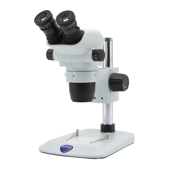
Overview SZO-B / SZO-T EYEPIECE PHOTO PORT (ONLY SZO-T) DIOPTRIC COMPENSATION RING ZOOM KNOB MICROSCOPE BODY SZO-B: BINOCULAR SZO-T: TRINOCULAR CLICK STOP SELECTOR Page 4... - Page 5 SZO-1 / SZO-2 EYEPIECE PHOTO PORT (ONLY SZO-2) DIOPTRIC COMPENSATION RING MICROSCOPE BODY SZO-1: BINOCULAR ZOOM KNOB SZO-2: TRINOCULAR CLICK STOP SELECTOR FIXING FOCUS KNOB SCREW STAGE CLIPS PILLAR BLACK&WHITE CONTRAST DISC MICROSCOPE BASE Page 5...
- Page 6 SZO-3 / SZO-4 EYEPIECE PHOTO PORT (ONLY SZO-4) DIOPTRIC COMPENSATION FIXING RING SCREW ZOOM KNOB REFLECTED LIGHT ILLUMINATOR CLICK STOP SELECTOR FOCUS KNOB MICROSCOPE BODY SZO-3: BINOCULAR SZO-4: TRINOCULAR REFLECTED LIGHT ON/OFF AND INTENSITY CONTROL PILLAR TRANSLUCENT DISC (TRANSMITTED LIGHT) OR BLACK&WHITE CONTRAST DISC (REFLECTED LIGHT) TRANSMITTED LIGHT ON/OFF...
- Page 7 SZO-5 / SZO-6 EYEPIECE PHOTO PORT (ONLY SZO-6) DIOPTRIC FIXING COMPENSATION RING SCREW ZOOM KNOB CLICK STOP SELECTOR FOCUS KNOB MICROSCOPE BODY SZO-5: BINOCULAR SZO-6: TRINOCULAR PILLAR TRANSMITTED LIGHT ON/OFF REFLECTED LIGHT ON/OFF AND INTENSITY CONTROL AND INTENSITY CONTROL STAGE CLIPS TRANSLUCENT DISC MICROSCOPE (TRANSMITTED LIGHT) OR...
-
Page 8: Szo-7 / Szo-8
SZO-7 / SZO-8 EYEPIECE PHOTO PORT (ONLY SZO-8) OVERHANGING STAND SZ-STL1 DIOPTRIC CLICK STOP COMPENSATION SELECTOR RING ZOOM KNOB MICROSCOPE BODY FOCUS KNOB SZO-7: BINOCULAR SZO-8: TRINOCULAR FIXING SCREW MICROSCOPE BASE Page 8... - Page 9 SZO-9 / SZO-10 OVERHANGING STAND SZ-STL2 EYEPIECE DIOPTRIC COMPENSATION PHOTO PORT RING (ONLY SZO-10) ZOOM KNOB FIXING SCREW FOCUS KNOB CLICK STOP SELECTOR MICROSCOPE BODY SZO-9: BINOCULAR SZO-10: TRINOCULAR MICROSCOPE BASE Page 9...
-
Page 10: Unpacking
Unpacking The microscope is housed in a moulded Styrofoam container. Remove the tape from the edge of the container and lift the top half of the container. Take some care to avoid that the optical items (objectives and eyepieces) fall out and get damaged. Using both hands (one around the arm and one around the base), lift the microscope from the container and put it on a stable desk. - Page 11 SZO-1 / SZO-2 ② ① ⑤ ③ ⑦ ④ ⑥ ⑧ ① Microscope body ⑤ Photo tube (only for SZO-2) (SZO-1 Binocular) / SZO-2 Trinocular) ⑥ Black/white plate ② Eyepieces ⑦ Dust cover ③ Microscope stand ⑧ Allen wrench (only for SZO-2) ④...
- Page 12 SZO-3 / SZO-4 ② ① ⑦ ⑨ ⑪ ③ ⑧ ⑤ ⑩ ④ ⑥ ① Microscope body ⑥ Transparent plate (SZO-3 Binocular) / SZO-4 Trinocular) ⑦ Incident light LED illuminator ② Eyepieces ⑧ Black/white plate ③ Microscope stand ⑨ Dust Cover ④...
- Page 13 SZO-5 / SZO-6 ② ① ③ ⑩ ⑧ ⑤ ④ ⑥ ⑦ ⑨ ① Microscope body ⑥ Transparent plate (SZO-5 Binocular) / SZO-6 Trinocular) ⑦ Black/white plate ② Eyepieces ⑧ Dust Cover ③ Microscope stand with LED flexible arm ⑨ Allen Wrench (only SZO-6) ④...
- Page 14 SZO-7 / SZO-8 ② ① ③ ⑤ ④ ④ ⑥ ① Microscope body ④ Photo tube (only SZO-8) (SZO-7 Binocular) / SZO-8 Trinocular) ⑤ Dust Cover ② Eyepieces ⑥ Allen Wrench (only SZO-8) ③ Microscope stand SZ-STL1 Page 14...
-
Page 15: Szo-9 / Szo-10
SZO-9 / SZO-10 ② ① ③ ⑤ ④ ⑥ ① Microscope body ④ Photo tube (only SZO-10) (SZO-9 Binocular) / SZO-10 Trinocular) ⑤ Dust Cover ② Eyepieces ⑥ Allen Wrench (only SZO-10) ③ Microscope stand SZ-STL2 Page 15... -
Page 16: Assembly Procedure (Szo-B / Szo-T)
Assembly procedure (SZO-B / SZO-T) 1. Remove the eyepieces dust caps and insert the eyepieces in the empty eyepiece sleeve. (Fig. 1) Fig. 1 2. Lock the eyepieces using the locking knob ①. ① (Fig. 2) IMG7009 Fig. 2 3. Insert the microscope into the head holder and lock the clamping knob ②. -
Page 17: Assembly Procedure (Szo-7 / Szo-8)
Only for SZO-3/4/5/6 4. Connect the jack of the power supply to the so- cket in the rear part of the microscope base. (Fig. Fig. 4 Assembly procedure (SZO-7 / SZO-8) HORIZONTAL ARM SLIDING FIXING KNOBS DROP PREVENTION RING FOCUS KNOB BASE VERTICAL ARM FIXING... - Page 18 3. Insert the drop preventing ring. (Fig. 7) Fig. 7 4. Insert the horizontal arm and lock it with the lo- cking knob. (Fig. 8 - 9) Fig. 8 Fig. 9 5. Install the focus holder. Unscrew the prevention knob ④, and insert the head holder arm ③ from above in the hole of the horizontal arm.
- Page 19 6. Lock the fixing knob ⑤ (Fig. 11) ⑤ Fig. 11 7. Install the head holder, lock the fixing knob ⑥ and screw the prevention knob ④ from below. (Fig. 12-13) 8. Insert the head into the head holder and lock the clamping knob ②.
-
Page 20: Assembly Procedure (Szo-9 / Szo-10)
7.10 Assembly procedure (SZO-9 / SZO-10) HORIZONTAL TILTING VERTICAL ARM SLIDING LOCK KNOB ARM FIXING FIXING KNOB KNOB DROP PREVENTION RING BASE FOCUS KNOB 1. Screw the pillar on the base. (Fig. 14) Fig. 14 2. Tighten the screw to lock the pillar. (Fig. 15) Fig. - Page 21 4. Insert the horizontal arm and lock it with the lo- cking knob ① (Fig. 17). For a bigger safety, lock the fixing screw ② with the provided allen wrench. (Fig. 18) ① Fig. 17 ② Fig. 18 5. Install the head holder. Unscrew the prevention knob ③...
-
Page 22: Using The Microscope
Using the microscope Adjusting interpupillary distance Hold the right and left eyepiece tube with both hands and adjust the interpupillary distance by moving the two parts until one circle of light can be seen. If two circles appear, the interpupillary distance is too big, and if two overlapped circles appear, the interpupilla- ry distance is too small. -
Page 23: Use Of Additional Lens
8.5 Magnification Select the desired magnification by adjusting the zoom knob. (Fig. 25) Change the eyepieces and/or add an appropriate additional lens if necessary The microscope body is equipped with a “click-stop” function that allows to obtain a precise setting of the desired magnification. -
Page 24: Video Capturing (Szo-2/4/6/8/10)
Video capturing (SZO-2/4/6/8/10) Two kinds of observation heads, binocular or trinocular, are available for the SZO series. Trinocular head can be connected to cameras via an adapter. (Fig. 28) Please refer to the adapter and camera manuals for further details. -
Page 25: Use Of The Overhanging Stand (Szo-9/10)
Swivel the head Unlock the fixing knob and rotate the head to the desired ④ swivel angle (left or right), then fix the knob again. (Fig. 32) ④ Fig. 32 Rotating the horizontal arm Loosen the horizontal arm fixing knob and rotate the ⑤... - Page 26 Tilting the head holder Loosen the knob (Fig. 36) on the right side of the head ⑦ holder. The tilting vertical arm can be moved. Once the desired angle is achieved, tighten the knob again. ⑦ Fig. 36 Swivel the head Unlock the fixing knob and rotate the head to the ⑧...
-
Page 27: Maintenance
Maintenance Microscopy environment This microscope is recommended to be used in a clean, dry and shock free environment with a temperature of 5°-40°C and a maximum relative humidity of 75 % (non condensing). Use a dehumidifier if needed. To think about when and after using the microscope •... -
Page 28: 10. Troubleshooting
10. Troubleshooting Review the information in the table below to troubleshoot operating problems. PROBLEM CAUSE SOLUTION I. Optical Section: The illumination is ON, but the field of The plug is not connected to the il- Connect the cable view is dark. lumination The brightness is too low Adjust to a proper setting... -
Page 29: Equipment Disposal
Equipment disposal Art.13 Dlsg 25 July 2005 N°151. “According to directives 2002/95/EC, 2002/96/EC and 2003/108/EC relating to the reduction in the use of hazardous substances in electrical and electronic equipment and waste disposal.” The basket symbol on equipment or on its box indicates that the product at the end of its useful life should be collected separately from other waste. - Page 30 OPTIKA S.r.l. ® Via Rigla, 30 - 24010 Ponteranica (BG) - ITALY Tel.: +39 035.571.392 info@optikamicroscopes.com - www.optikamicroscopes.com OPTIKA Spain spain@optikamicroscopes.com OPTIKA USA usa@optikamicroscopes.com OPTIKA China china@optikamicroscopes.com OPTIKA India india@optikamicroscopes.com OPTIKA Central America camerica@optikamicroscopes.com...
- Page 31 Serie SZO MANUALE DI ISTRUZIONI Modello SZO-1 SZO-2 SZO-3 SZO-4 SZO-5 SZO-6 SZO-7 SZO-8 SZO-9 SZO-10 Ver. 2 2018...
- Page 32 Indice Avvertenza Simboli Informazioni sulla sicurezza Utilizzo previsto Panoramica SZO-B / SZO-T SZO-1 / SZO-2 SZO-3 / SZO-4 SZO-5 / SZO-6 SZO-7 / SZO-8 SZO-9 / SZO-10 Disimballaggio Assemblaggio SZO-B / SZO-T SZO-1 / SZO-2 SZO-3 / SZO-4 SZO-5 / SZO-6 SZO-7 / SZO-8 SZO-9 / SZO-10 Procedura di assemblaggio (SZO-B / SZO-T)
-
Page 33: Simboli
Avvertenza Questo microscopio è uno strumento scientifico di alta precisione, progettato per durare a lungo con una mini- ma manutenzione; la realizzazione è secondo i migliori standard ottici e meccanici, per poter essere utilizzato quotidianamente. Vi ricordiamo che questo manuale contiene informazioni importanti per la sicurezza e per la manutenzione dello strumento, e deve quindi essere messo a disposizione di coloro che lo utilizzeranno. -
Page 34: Panoramica
Panoramica SZO-B / SZO-T OCULARE USCITA FOTO (SOLO SZO-T) ANELLO COMPENSAZIONE DIOTTRICA SELETTORE ZOOM CORPO MICROSCOPIO SZO-B: BINOCULARE SZO-T: TRINOCULARE SELETTORE CLICK STOP Pagina 34... - Page 35 SZO-1 / SZO-2 OCULARE USCITA FOTO (SOLO SZO-2) ANELLO COMPENSAZIONE DIOTTRICA CORPO MICROSCOPIO SELETTORE SZO-1: BINOCULARE ZOOM SZO-2: TRINOCULARE SELETTORE CLICK STOP VITE DI MANOPOLA FISSAGGIO DI MESSA A FUOCO MOLLETTINE COLONNA DISCO DI CONTRASTO BIANCO/NERO BASE DEL MICROSCOPIO Pagina 35...
-
Page 36: Szo-3 / Szo-4
SZO-3 / SZO-4 OCULARE USCITA FOTO (SOLO SZO-4) ANELLO VITE DI COMPENSAZIONE FISSAGGIO DIOTTRICA SELETTORE ZOOM ILLUMINATORE LUCE RIFLESSA SELETTORE CLICK STOP MANOPOLA CORPO MICROSCOPIO DI MESSA A SZO-3: BINOCULARE FUOCO SZO-4: TRINOCULARE MANOPOLA ON/OFF E REGOLAZIONE INTENSITÀ LUCE INCIDENTE COLONNA DISCO TRASLUCIDO (LUCE TRASMESSA) O... - Page 37 SZO-5 / SZO-6 OCULARE USCITA FOTO (SOLO SZO-6) ANELLO COMPENSAZIONE VITE DI DIOTTRICA FISSAGGIO SELETTORE ZOOM SELETTORE CLICK STOP MANOPOLA DI MESSA A CORPO MICROSCOPIO FUOCO SZO-5: BINOCULARE SZO-6: TRINOCULARE COLONNA MANOPOLA ON/OFF E MANOPOLA ON/OFF E REGOLAZIONE INTENSITÀ REGOLAZIONE INTENSITÀ LUCE TRASMESSA LUCE INCIDENTE MOLLETTINE...
-
Page 38: Szo-7 / Szo-8
SZO-7 / SZO-8 OCULARE USCITA FOTO (SOLO SZO-8) STATIVO A SBALZO SZ-STL1 ANELLO SELETTORE COMPENSAZIONE CLICK STOP DIOTTRICA SELETTORE ZOOM CORPO MICROSCOPIO MANOPOLA SZO-7: BINOCULARE DI MESSA A SZO-8: TRINOCULARE FUOCO VITE DI FISSAGGIO BASE DEL MICROSCOPIO Pagina 38... - Page 39 SZO-9 / SZO-10 STATIVO A SBALZO SZ-STL2 OCULARE ANELLO USCITA FOTO COMPENSAZIONE (SOLO SZO-10) DIOTTRICA SELETTORE ZOOM VITE DI FISSAGGIO MANOPOLA DI MESSA A SELETTORE FUOCO CLICK STOP CORPO MICROSCOPIO SZO-9: BINOCULARE SZO-10: TRINOCULARE BASE DEL MICROSCOPIO Pagina 39...
-
Page 40: Disimballaggio
Disimballaggio Il microscopio si trova in un imballaggio di polistirolo espanso stampato. Dopo aver tolto il nastro adesivo da tutti gli imballi, sollevare la metà superiore dell’imballaggio. Fare attenzione a non far cadere o danneggiare i com- ponenti ottici (obiettivi e oculari). Estrarre il microscopio dal suo imballaggio con entrambe le mani (una intorno al braccio e una intorno alla base) e appoggiarlo su un piano stabile. - Page 41 SZO-1 / SZO-2 ② ① ⑤ ③ ⑦ ④ ⑥ ⑧ ① Corpo del microscopio ⑤ Foto tubo (solo per SZO-2) (SZO-1 Binoculare) / SZO-2 Trinoculare) ⑥ Disco bianco / nero ② Oculari ⑦ Copertina antipolvere ③ Stativo ⑧ Brugola (solo per SZO-2) ④...
- Page 42 SZO-3 / SZO-4 ② ① ⑦ ⑨ ⑪ ③ ⑧ ⑤ ⑩ ④ ⑥ ① Corpo del microscopio ⑥ Disco trasparente (SZO-3 Binoculare) / SZO-4 Trinoculare) ⑦ Illuminatore LED luce incidente ② Oculari ⑧ Disco bianco / nero ③ Stativo ⑨...
- Page 43 SZO-5 / SZO-6 ② ① ③ ⑩ ⑧ ⑤ ④ ⑥ ⑦ ⑨ ① Corpo del microscopio ⑥ Disco trasparente (SZO-5 Binoculare) / SZO-6 Trinoculare) ⑦ Disco bianco / nero ② Oculari ⑧ Copertina antipolvere ③ Stativo con bracci LED autoportanti ⑨...
- Page 44 SZO-7 / SZO-8 ② ① ③ ⑤ ④ ④ ⑥ ① Corpo del microscopio ④ Foto tubo (solo per SZO-8) (SZO-7 Binoculare) / SZO-8 Trinoculare) ⑤ Copertina antipolvere ② Oculari ⑥ Brugola (solo per SZO-8) ③ Stativo SZ-STL1 Pagina 44...
- Page 45 SZO-9 / SZO-10 ② ① ③ ⑤ ④ ⑥ ① Corpo del microscopio ④ Foto tubo (solo per SZO-10) (SZO-9 Binoculare) / SZO-10 Trinoculare) ⑤ Copertina antipolvere ② Oculari ⑥ Brugola (solo per SZO-10) ③ Stativo SZ-STL2 Pagina 45...
-
Page 46: Procedura Di Assemblaggio (Szo-B / Szo-T)
Procedura di assemblaggio (SZO-B / SZO-T) 1. Rimuovere i tappi antipolvere dai portaoculari ed inserire gli oculari. (Fig. 1) Fig. 1 ① 2. Bloccare gli oculari serrando la vitina di bloccag- gio ①. (Fig. 2) IMG7009 Fig. 2 3. Inserire il corpo del microscopio nel supporto e fissare la vite di bloccaggio ②. -
Page 47: Procedura Di Assemblaggio (Szo-7 / Szo-8)
Solo per SZO-3/4/5/6 7. Collegare lo spinotto dell’alimentatore al connet- tore posto nella parte posteriore della base del microscopio. (Fig. 4) Fig. 4 Procedura di assemblaggio (SZO-7 / SZO-8) VITE DI FISSAGGIO SCORRIMENTO BRACCIO ORIZZONTALE ANELLO DI PREVENZIONE DISCESA MANOPOLA DI MESSA A FUOCO BASE VITE DI... - Page 48 3. Inserire l’anello di prevenzione discesa. (Fig. 7) Fig. 7 4. Inserire il braccio orizzontale e bloccarlo con la vite di fissaggio. (Fig. 8 - 9) Fig. 8 Fig. 9 5. Installare il supporto. Svitare la manopola di bloc- co ④ ed inserire dall’alto il braccio per il supporto della messa a fuoco ③...
- Page 49 6. Bloccare la vite di fissaggio ⑤ (Fig. 11) ⑤ Fig. 11 7. Installare il supporto della messa a fuoco, serrare la vite di fissaggio ⑥ ed avvitare nuovamente la manopola di blocco ④ dal basso. (Fig. 12-13) 8. Inserire il corpo del microscopio nel supporto e fissare la vite di bloccaggio ②.
-
Page 50: Procedura Di Assemblaggio (Szo-9 / Szo-10)
7.10 Procedura di assemblaggio (SZO-9 / SZO-10) MANOPOLA DI VITE DI FISSAGGIO VITE DI FISSAGGIO FISSAGGIO SCORRIMENTO INCLINAZIONE BRACCIO BRACCIO ORIZZONTALE VERTICALE ANELLO PREVENZIONE DISCESA BASE MANOPOLA DI MESSA A FUOCO 1. Avvitare la colonna alla base. (Fig. 14) Fig. 14 2. - Page 51 4. Inserire il braccio orizzontale e bloccarlo con la vite di fissaggio ① (Fig. 17). Per una maggiore sicurezza, serrare la vite di fissaggio ② con la brugola in dotazione. (Fig. 18) ① Fig. 17 ② Fig. 18 5. Installare il supporto di messa a fuoco. Svitare la manopola di blocco ③...
-
Page 52: Uso Del Microscopio
Uso del microscopio Regolazione della distanza interpupillare Afferrare con entrambe le mani i portaoculari destro e sinistro e regolare la distanza interpupillare spostan- do I tubi fino a che si osserva una sola immagine. Se si osservano due immagini la distanza è troppo ele- vata, mentre se si osservano due cerchi sovrapposti, la distanza è... -
Page 53: Disco Di Contrasto (Szo-1/2/34/5/6)
Ingrandimento Selezionare l’ingrandimento desiderato mediante il selettore zoom. (Fig. 25) Se necessario usare oculari diversi e/o un’adeguata lente addizionale per ottenere l’ingrandimento voluto. Il corpo del microscopio è dotato di una funzione “clic stop” che consente di ottenere un ingrandimento preciso. -
Page 54: Microfotografia (Szo-2/4/6/8/10)
8.8 Microfotografia (SZO-2/4/6/8/10) Sono disponibili due teste osservazione, binoculare o trinoculare, nella serie SZO. La testa trinoculare può essere collegata ad una telecamera mediante un adattatore.(Fig. 28) Consultare il manuale delle telecamere e degli adattatori per maggiori dettagli. Fig. 28 Uso dell’illuminazione (SZO-3/4/5/6) ②... -
Page 55: Uso Della Base A Sbalzo (Szo-9/10)
Angolare la testa Allentare la vite di fissaggio ④ e ruotare la testa fino all’angolo desiderato (destra o sinistra), quindi serrare la vite di fissaggio. (Fig. 32) ④ Fig. 32 Ruotare il braccio orizzontale Allentare la vite di fissaggio del braccio orizzontale ⑤ e ruotare il braccio, quindi serrare la vite di fissaggio. - Page 56 Inclinare il supporto della testa Allentare la manopola (Fig. 36) sulla parte destra ⑦ del supporto. Il braccio verticale inclinabile può essere spostato. Una volta raggiunto l’angolo desiderato, serrare la manopola. ⑦ Fig. 36 Angolare la testa Allentare la vite di fissaggio e ruotare la testa fino ⑧...
-
Page 57: Manutenzione
Manutenzione Ambiente di lavoro Si consiglia di utilizzare il microscopio in un ambiente pulito e secco, privo di urti, ad una temperatura fra 0°C e 40°C e con una umidità relativa massima dell’85% (in assenza di condensazione). Si consiglia l’uso di un deumidificatore se necessario. -
Page 58: Guida Alla Risoluzione Dei Problemi
10. Guida alla risoluzione dei problemi Consultare le informazioni riportate nella tabella seguente per risolvere eventuali problemi operativi. PROBLEMA CAUSA SOLUZIONE I. Sezione Ottica: Il LED è acceso, ma il campo visivo L’alimentatore è scollegato. Collegarlo è scuro La luminosità è troppo bassa Regolarla ad un livello adeguato I bordi del campo visivo sono L’illuminatore per luce incidente non... -
Page 59: Smaltimento
Smaltimento Ai sensi dell’articolo 13 del decreto legislativo 25 luglio 2005 n°151. “Attuazione delle direttive 2002/95/CE, 2002/96/CE e 2003/108/CE, relative alla riduzione dell’uso di sostanze pericolose nelle apparecchiature elettri- che ed elettroniche, nonché allo smaltimento dei rifiuti”. Il simbolo del cassonetto riportato sulla apparecchiatura o sulla sua confezione indica che il prodotto alla fine della propria vita utile deve essere raccolto separatamente degli altri rifiuti. - Page 60 OPTIKA S.r.l. ® Via Rigla, 30 - 24010 Ponteranica (BG) - ITALY Tel.: +39 035.571.392 info@optikamicroscopes.com - www.optikamicroscopes.com OPTIKA Spain spain@optikamicroscopes.com OPTIKA USA usa@optikamicroscopes.com OPTIKA China china@optikamicroscopes.com OPTIKA India india@optikamicroscopes.com OPTIKA Central America camerica@optikamicroscopes.com...
Need help?
Do you have a question about the SZO Series and is the answer not in the manual?
Questions and answers