Advertisement
Available languages
Available languages
Quick Links
Advertisement

Related Manuals for Optika Italy Modular Series


Summary of Contents for Optika Italy Modular Series
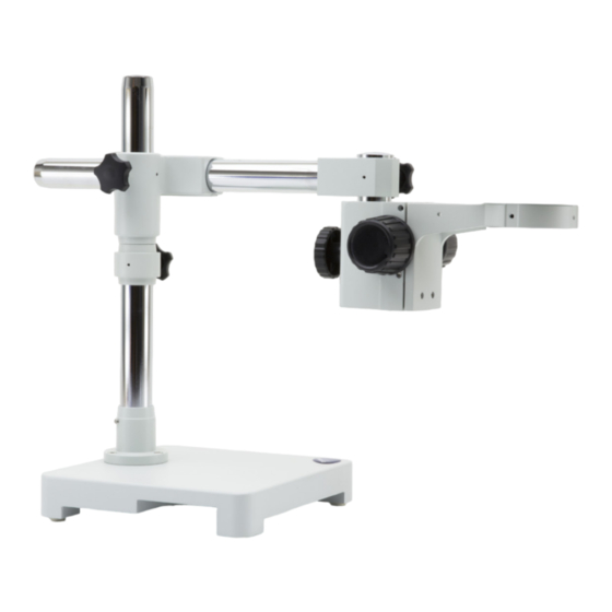
- Page 1 Modular Series INSTRUCTION MANUAL Model SZ-STL1 SZ-STL1H SZ-STL2 SZ-STL2H v 1.0 2018...
- Page 2 SUMMARY Warning Intended use Overview Assembly Using the base Equipment disposal Page 2...
- Page 3 Warning This microscope is a scientific precision instrument designed to last for many years with a minimum of maintenance. It is built to high optical and mechanical standards and to withstand daily use. We remind you that this manual contains important information on safety and maintenance, and that it must therefore be made accessible to the instrument users.
- Page 4 Assembly (SZ-STL1 / SZ-STL1H) 1. Screw the pillar on the base. (Fig. 1) 2. Tighten the screw to lock the pillar. (Fig. 2) 3. Insert the drop preventing ring. (Fig. 3) 4. Insert the horizontal arm and lock it with the locking knob. (Fig. 4 & 5) 5.
- Page 5 ► ONLY FOR SZ-STL1H: 6. Install the head holder, lock the fixing knob and screw the prevention knob from below. (fig. 8-9) ② ② Fig.8 Fig.9 Page 5...
- Page 6 Assembly (SZ-STL2 / SZ-STL2H) 1. Screw the pillar on the base (Fig. 10) 2. Tighten the screw to lock the pillar (Fig. 11) 3. Insert the drop preventing ring. (Fig. 12) 4. Insert the horizontal arm and lock it with the locking knob (Fig.13).
- Page 7 ► ONLY FOR SZ-STL2H: 6. Install the head holder. Unscrew the prevention knob and insert the head holder from below in the ① ② vertical arm. (fig. 15-16). At the end screw again the prevention knob. ② ① Fig.15 Fig.16 Page 7...
- Page 8 Using the base SZ-STL1 / SZ-STL1H: Moving the horizontal arm (Fig. 17). ① Unlock the knob on the right side of the horizontal ①. The arm can be extended or shortened according Fig.17 to specific needs. (Fig. 18-19) Fig.18 Fig.19 ① Swivel the head (Fig. 20) Unlock the fixing knob and rotate the head to ①...
- Page 9 Rotating the horizontal arm (Fig. 21) Loosen the horizontal arm fixing knob ② rotate the arm, then fix again the fixing knob. ② NOTE: 180° rotation of the microscope ► with respect to the base could cause a rollover of the entire system. Adjusting the tension of the focus knob (Fig. Fig.21 ► This adjustment allows to increase or decrease the tension of the knob by avoiding an involuntary descent of the microscope body under its own weight. Adjust the tension just above...
- Page 10 Using the base SZ-STL2 / SZ-STL2H: ① Moving the horizontal arm (Fig. 23). Unlock the knob on the left side of the horizontal ①. The arm can be extended or shortened according Fig.23 to specific needs. (Fig. 24-25) Fig.24 Fig.25 Tilting of the head holder. (Fig. 26) Loosen the knob ②...
- Page 11 Equipment disposal Art.13 Dlsg 25 july 2005 N°151. “According to directives 2002/95/EC, 2002/96/EC and 2003/108/EC relating to the reduction in the use of hazardous substances in electrical and electronic equipment and waste disposal.” The basket symbol on equipment or on its box indicates that the product at the end of its useful life should be collected separately from other waste.
- Page 12 Page 12...
- Page 13 Serie Modulare MANUALE D’ISTRUZIONI Modello SZ-STL1 SZ-STL1H SZ-STL2 SZ-STL2H v 1.0 2018...
- Page 14 INDICE Avvertenza Utilizzo previsto Panoramica Assemblaggio Uso della base Smaltimento Pagina 14...
- Page 15 Avvertenza Questo microscopio è uno strumento scientifico di alta precisione, progettato per durare a lungo con una mini- ma manutenzione; la realizzazione è secondo i migliori standard ottici e meccanici, per poter essere utilizzato quotidianamente. Vi ricordiamo che questo manuale contiene informazioni importanti per la sicurezza e per la manutenzione dello strumento, e deve quindi essere messo a disposizione di coloro che lo utilizzeranno.
- Page 16 Assemblaggio (SZ-STL1 / SZ-STL1H) 1. Avvitare la colonna alla base. (Fig. 1) 2. Serrare la vite per bloccare la colonna. (Fig. 2) 3. Inserire l’anello di prevenzione discesa. (Fig. 3) 4. Inserire il braccio orizzontale e bloccarlo con la vite di fissaggio. (Fig. 4 & 5) 5.
- Page 17 ► SOLO PER SZ-STL1H: 6. Installare il supporto di messa a fuoco, serrare la vite di fissaggio ed avvitare nuovamente la manopola di blocco del basso. (fig. 8-9) ② ② Fig.8 Fig.9 Pagina 17...
- Page 18 Assemblaggio (SZ-STL2 / SZ-STL2H) 1. Avvitare la colonna alla base. (Fig. 10) 2. Serrare la vite per bloccare la colonna. (Fig. 11) 3. Inserire l’anello di prevenzione discesa. (Fig. 12) 4. Inserire il braccio orizzontale e bloccarlo con la vite di fissaggio (Fig.13).
- Page 19 ► SOLO PER SZ-STL2H: 6. Installare il supporto di messa a fuoco. Svitare la manopola di blocco ed inserire il supporto di messa a ① fuoco dal basso nel braccio verticale. (fig. 15-16). Al termine riavvitare la manopola di blocco. ② ② ①...
- Page 20 Uso della base SZ-STL1 / SZ-STL1H: Muovere il braccio orizzontale (Fig. 17). ① Allentare le viti di fissaggio sul lato destro del braccio orizzontale ①. Il braccio può essere esteso o accorciato in Fig.17 funzione delle singole necessità. (Fig. 18-19) Fig.18 Fig.19 ①...
- Page 21 Ruotare il braccio orizzontale (Fig. 21) Allentare la vite di fissaggio del braccio orizzontale e ruotare il braccio, quindi ② serrare nuovamente a vite. ② NOTA: la rotazione di 180° del ► microscopio rispetto alla base potrebbe causare un ribaltamento dell’intero sistema.
- Page 22 Uso della base SZ-STL2 / SZ-STL2H: ① Muovere il braccio orizzontale (Fig. 23). Allentare le viti di fissaggio sul lato sinistro del braccio orizzontale ①. Il braccio può essere esteso o accorciato in Fig.23 funzione delle singole necessità. (Fig. 24-25) Fig.24 Fig.25 Inclinare il supporto di messa a fuoco.
- Page 23 Smaltimento Ai sensi dell’articolo 13 del decreto legislativo 25 luglio 2005 n°151. “Attuazione delle direttive 2002/95/CE, 2002/96/CE e 2003/108/CE, relative alla riduzione dell’uso di sostanze pericolose nelle apparecchiature elettriche ed elettroniche, nonché allo smaltimento dei rifiuti”. Il simbolo del cassonetto riportato sulla apparecchiatura o sulla sua confezione indica che il prodotto alla fine della propria vita utile deve essere raccolto separatamente degli altri rifiuti.
- Page 24 OPTIKA S.r.l. ® Via Rigla, 30 - 24010 Ponteranica (BG) - ITALIA Tel.: +39 035.571.392 - Fax: +39 035.571.435 info@optikamicroscopes.com - www.optikamicroscopes.com OPTIKA Spain spain@optikamicroscopes.com OPTIKA USA usa@optikamicroscopes.com OPTIKA China china@optikamicroscopes.com OPTIKA Hungary hungary@optikamicroscopes.com OPTIKA India india@optikamicroscopes.com...
Need help?
Do you have a question about the Modular Series and is the answer not in the manual?
Questions and answers