
Related Manuals for TSI Instruments AirAssure 8144


Summary of Contents for TSI Instruments AirAssure 8144
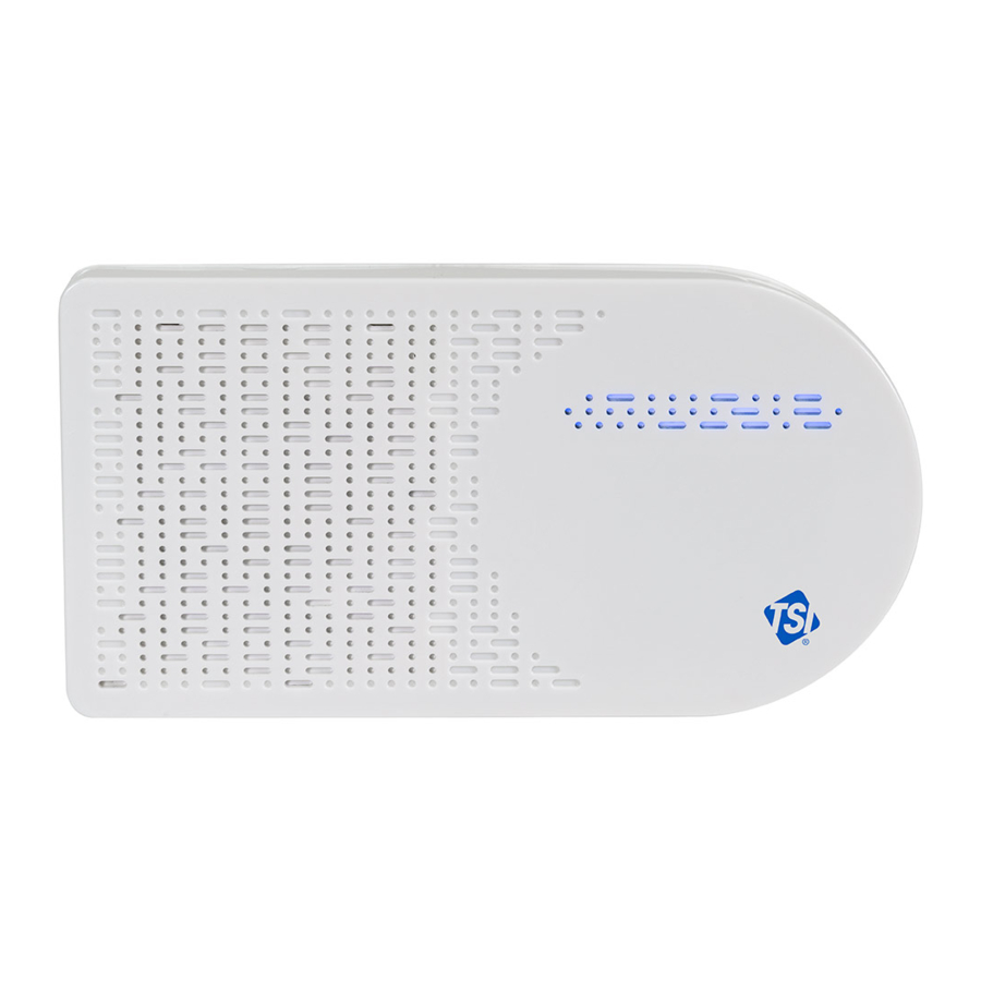
- Page 1 AirAssure ™ Indoor Air Quality Monitor Model 8144 Operation and Maintenance Manual P/N 6015658, Revision E November 2022 www.tsi.com...
- Page 2 Start Seeing the Benefits of Registering Today! ® ® Thank you for your TSI instrument purchase. Occasionally, TSI releases information on software updates, product enhancements and ® new products. By registering your instrument, TSI will be able to send this important information to you. http://register.tsi.com As part of the registration process, you will be asked for your comments on TSI products and services.
- Page 3 Copyright© TSI Incorporated / 2021–2022 / All rights reserved. Part Number 6015658 / Revision E / November 2022 Address TSI Incorporated / 500 Cardigan Road / Shoreview, MN 55126 / USA Fax No. (651) 490-3824 LIMITATION OF WARRANTY AND LIABILITY (effective February 2020) (For country-specific terms and conditions outside of the USA, please visit www.tsi.com.) Seller warrants the goods, excluding software, sold hereunder, under normal use and service as described in the operator's manual, to be free from defects in...
- Page 4 TO THE EXTENT PERMITTED BY LAW, THE EXCLUSIVE REMEDY OF THE USER OR BUYER, AND THE LIMIT OF SELLER'S LIABILITY FOR ANY AND ALL LOSSES, INJURIES, OR DAMAGES CONCERNING THE GOODS (INCLUDING CLAIMS BASED ON CONTRACT, NEGLIGENCE, TORT, STRICT LIABILITY OR OTHERWISE) SHALL BE THE RETURN OF GOODS TO SELLER AND THE REFUND OF THE PURCHASE PRICE, OR, AT THE OPTION OF SELLER, THE REPAIR OR REPLACEMENT OF THE GOODS.
-
Page 5: Table Of Contents
Contents Contents ....................... iii Safety Information ..................v Description of Caution/Warning Symbols ..........v Caution ....................v Warning ....................v Caution and Warning Symbols ..............v Laser Safety ................... vii Labels ....................viii Reusing and Recycling ................viii Chapter 1 Product Overview ............... 1 Unpacking .................... - Page 6 Appendix A Specifications* ............... 39 Appendix B Status Flags and Error Codes ..........43 Examples: ....................46...
-
Page 7: Safety Information
Safety Information Description of Caution/Warning Symbols Appropriate caution/warning statements are used throughout the manual and on the instrument that require you to take cautionary measures when working with the instrument. Caution C A U T I O N Failure to follow the procedures prescribed in this manual might result in irreparable equipment damage. - Page 8 W A R N I N G • Use of components other than those specified by ® ® Incorporated (TSI ) may impair the safety features provided by the equipment. • When mains power adapters are used, the equipment should be positioned so the mains plug will remain accessible for emergency disconnect.
-
Page 9: Laser Safety
Laser Safety • AirAssure™ Indoor Air • You will not be exposed to Quality monitors are Class 1 the laser radiation when the AirAssure™ IAQ monitor is laser-based instruments. disassembled. • During normal operation, • The PM sensor has a laser you will not be exposed to laser radiation. -
Page 10: Labels
Labels Advisory labels and identification labels are attached to the instrument. 1. Serial Number Label (back) 2. Laser Radiation Label (internal, on the PM sensor) FCC ID: 2AC7Z-ESPWROVERE Safety Details Contains IC ID: 2AC7Z-ESPWROVERE 4. European symbol for non-disposable item. Item must be recycled. -
Page 11: Chapter 1 Product Overview
Chapter 1 Product Overview Incorporated’s AirAssure™ Indoor Air Quality Monitor is a ® real-time Particulate Matter (PM) and Gas monitor designed to provide accurate gas and mass concentrations as well as temperature, humidity, and barometric pressure measurements. The monitor is designed to be deployed in less than ten minutes and is intended for indoor air quality monitoring only. -
Page 12: Unpacking
Unpacking Compare all the components you received with those listed in the table below. Item Description AirAssure™ Indoor Air Quality Monitor USB Power Supply Country Specific Plug Adapter Kit 2m USB-A to USB-C Cable 24 VAC Terminal Connector 32 GB microSD card (installed) Mounting Kit: (2 screw and plug sets,... -
Page 13: Airassure™ Iaq Monitor Replacement Parts
AirAssure™ IAQ Monitor Replacement Parts Listed below are replacement items for the AirAssure™ Indoor Air ® Quality Monitor. Contact for purchase information. Part Item Number Description Replacement 2-Gas Variant Sensor Cartridge: tVOC, Temperature, 814408 Relative Humidity, and Barometric Pressure Replacement 4-Gas Variant Sensor Cartridge: CO, 814401... - Page 14 Part Item Number Description Replacement CO 814404 Sensor Replacement 814405 Formaldehyde Sensor Replacement 814406 Power Supply Kit Replacement 814407 Membrane Filters (pack of 3) Chapter 1...
-
Page 15: Chapter 2 Setting Up
Chapter 2 Setting Up The AirAssure™ Indoor Air Quality Monitor is delivered fully assembled and ready to be mounted on an interior wall. Start by unpacking the device and its contents from the shipping package. ® The monitor is intended to be connected to local 2.4 GHz Wi-Fi ®... -
Page 16: Activating A New Device(S)
N O T I C E Some corporate networks require the device MAC address for security. This can be found on the serial number label of the monitor. C A U T I O N NEVER open the monitor when it is powered on or connected to the power adapter! The monitor contains very sensitive sensors that are susceptible to electro-... -
Page 17: Connecting Airassure™ Monitor To A Wi-Fi Network
3. Once you are logged in, click on the plus icon in the lower right. Hovering over it will show “Activate New Device.” 4. Enter the required information into the fields. The serial number can be found on the back of the device. You can also name the device, configure its location and whether or not you would like to make the data public. - Page 18 1. Remove the power supply, plug adapter kit, and USB-C cable from its packaging. Select your region’s plug connector and mate it to the power supply by “snapping” the plug connector into the adapter. 2. Connect the other end of the USB cable to the USB-C port on the bottom of the monitor.
- Page 19 4. The monitor should turn on as indicated by the light bar on the front. To connect the monitor to the internet, you first have to connect to the monitor’s hot spot. 5. Pulse yellow indicates that the monitor is in set up mode as a ®...
- Page 20 7. With your phone camera, scan the QR code at the top of the label to connect to the monitor’s Wi-Fi ® hotspot. You should be ® prompted to connect to a new Wi-Fi network called “AirAssure IAQ 8144XXX…” 8. If you are not connected automatically, you can still connect ®...
- Page 21 9. Once connected to the AirAssure™ IAQ monitor Wi-Fi ® network, use your phone camera again to connect to the setup web page or open your phone browser and enter a URL of 192.168.4.1. 10. You should see a web page like the one below. Select your home ®...
- Page 22 ® 11. Enter the local Wi-Fi password and click Save. 12. The monitor should automatically power cycle and start again with a pulsing yellow LED light bar. 13. The process of connecting to your local internet will be reflected in the color sequence shown below. This may take several minutes.
- Page 23 14. If all connections are made, the LED will be solid blue. 15. You should now be able to see measurement data from the device. Be patient, as it may take a few minutes for the device to start reporting its data to the cloud. 16.
-
Page 24: Installing The Airassure™ Indoor Air Quality Monitor
Installing the AirAssure™ Indoor Air Quality Monitor The AirAssure™ IAQ monitor can be mounted using screws or using ® ® double-sided tape (such as 3M Command strips). Power can be supplied using either the wall plug or building-supplied 24 VAC from inside a wall. - Page 25 3. If using screws, position the template from the quick start guide and use the included level to mark the screw locations on the wall for mounting. If using a wall plug, install the screws and mount the monitor. 4. If using 24 VAC power, mark the cut-out guide area for the wiring feed through (large circle or rectangle).
- Page 26 6. Before applying power to the connection, insert the 24 VAC plug into back of monitor and mount it on the wall. 7. If the screws need to be more secure, press gently on the two pads on top of the front cover and push down and away from the wall.
- Page 27 9. When power is now applied, the light bar on the monitor will illuminate and pulse yellow. 10. The process of connecting to your local internet will be reflected in the color sequence shown below. This may take several minutes. The LED light bar should be solid blue. Cloud ®...
-
Page 28: Getting Help
Getting Help Please check the Help Center at: www.tsilink.com Click on “Help” and “Contact Support.” Send the support team a message by filling out the form and clicking “Send.” Technical Contacts If you have any difficulty setting up or operating the AirAssure™ Indoor Air Quality monitor, or if you have technical or application ®... -
Page 29: International Contacts
International Contacts Service TSI Instruments Singapore Pte Ltd 150 Kampong Ampat #05-05 KA Centre Singapore 368324 Telephone: +65 6595-6388 Fax: +65 6595-6399 E-mail: tsi-singapore@tsi.com TSI Instrument (Beijing) Co., Ltd. Unit 1201, Pan-Pacific Plaza No. 12 A, Zhongguancun South Avenue Haidian District, Beijing, 100181... - Page 30 E-mail: tsibeijing@tsi.com TSI GmbH Neuköllner Strasse 4 52068 Aachen GERMANY Telephone: +49 241-52303-0 E-mail: tsigmbh@tsi.com TSI Instruments Ltd. Stirling Road Cressex Business Park High Wycombe, Buckinghamshire HP12 3ST UNITED KINGDOM Telephone: +44 (0) 149 4 459200 E-mail: tsiuk@tsi.com TSI France Inc.
-
Page 31: Chapter 3 Operation
Chapter 3 Operation Overview The AirAssure™ Indoor Air Quality (IAQ) Monitor’s primary use is for indoor applications. It is designed to operate 24/7 when powered by a power outlet or 24 Volts AC low-voltage building power. Once you have setup your monitor(s) and connected them to a local wireless ®... -
Page 32: How To Download Data From One Or More Airassure™ Iaq Monitors
How to Download Data from one or more AirAssure™ IAQ Monitors 1. Go to www.tsilink.com and log in. 2. Click on the map and zoom in to the area where your AirAssure™ IAQ device pin is located. 3. Click on the device pin. 4. -
Page 33: Interpreting The Data Downloaded From The Microsd Card Or From The Cloud
Interpreting the Data Downloaded from the microSD Card or from the Cloud Data downloaded from the AirAssure™ Indoor Air Quality Monitor from the microSD card or cloud is stored as an ASCII format file with the serial number and date as the filename and .csv as the extension (e.g. -
Page 34: Logging Interval Options And How To Change The Settings
Logging Interval Options and How to Change the Settings By default, the AirAssure™ Indoor Air Quality Monitor will log a sample (data point) every 15 minutes. Available logging intervals include 1, 5, 10, 15, 30 and 60 minutes. The logging interval can be changed by logging into TSILINK.com and accessing the device settings. - Page 35 Operation...
- Page 36 (This page intentionally left blank) Chapter 3...
-
Page 37: Chapter 4 Maintenance
Chapter 4 Maintenance ® Replacement sensors can be ordered from TSI Incorporated. Although sensor life times vary depending on the conditions they are exposed to, conservative recommended replacement intervals are listed below for each sensor: N O T I C E Recommend replacement intervals are derived from the expected indoor conditions: Temperature (65 to 75°F/18 to 24°C) and Relative Humidity (30 to 50%). - Page 38 Recommended Part Replacement Item Number Description Interval Membrane Filters Replace when 814407 (Pack of 3) replacing the gas sensors above ® 814403 Calibrated 3 years PM Replacement Sensor 814404 Replacement 3 years Sensor 814405 Formaldehyde 1 year Replacement Sensor 1. Any maintenance should be performed only after powering the unit down by disconnecting the USB cable from the power adapter or removing the unit from the wall and disconnecting the 24 VAC power connector from the back panel.
-
Page 39: Replacing The Multi-Sensor Cartridge And Membrane
2. There are two indents at the top of the unit indicating where to press down and out to separate the cover from the base. The cover will pivot from the bottom allowing the cover to be removed. 3. You can identify the sensors based on the table above and picture below. -
Page 40: Replacing The Pm Sensor
5. Replace the cover, power up the monitor and connect it to the cloud to register the new sensors and their calibration values. Replacing the PM Sensor 1. Unplug the connector on the left by pressing the locking clips in from the top and bottom and pulling the connector straight out. -
Page 41: Replacing The Co Sensor
Replacing the CO Sensor 1. Unplug the connector on the left by pressing the locking clips in from the top and bottom and pulling the connector straight out. 2. Pull the sensor module from the top and straight away from the case. - Page 42 2. Depress the back of the cable connector (pushing into the page in the picture below). 3. Pull the connector from the top and up. 4. Pull the sensor module PC-board from the top and straight away from the wall. You may have to wiggle it up and down to release. Chapter 4...
- Page 43 5. Reverse the steps for the new sensor. 6. Replace the cover, power up the monitor and connect it to the cloud to register the new sensor and its calibration values. Maintenance...
- Page 44 (This page intentionally left blank) Chapter 4...
-
Page 45: Chapter 5 Troubleshooting
Chapter 5 Troubleshooting Detailed troubleshooting and frequently asked questions can be found at https://tsi.com/resources/airassure-iaq-monitors-faqs/ The table below lists some symptoms, possible causes, and recommended solutions for common problems encountered with the AirAssure™ Indoor Air Quality Monitor. Possible Cause Corrective Action The AirAssure™... - Page 46 Possible Cause Corrective Action Cannot connect to Note that AirAssure™ IAQ monitor can only connect ® ® ® Wi-Fi or the to 2.4 GHz Wi-Fi signals. Most Wi-Fi routers internet. provide several frequency channels. Please make sure you are connecting to the 2.4 GHz channel. The monitor does not have the capability to connect to public networks that require a second step of browser authentication, such as a free public hotel or...
- Page 47 Possible Cause Corrective Action PM or gas readings are not correct ® Custom calibration Check the custom calibration factor on TSI Link. Is factor is incorrect the value correct? Was it changed by mistake? No custom Values can be corrected by using a custom calibration factor calibration factor.
- Page 48 (This page intentionally left blank) Chapter 5...
- Page 49 Appendix A Specifications* Overall Operating Temp Range ..0 to 40ºC (32 to 104ºF) Operating Humidity Range ..15 to 95% non-condensing Storage Temperature ..... 5 to 30ºC (41 to 86ºF) 171 mm x 89 mm x 33 mm Case Dimensions ....6.75 in.
- Page 50 Gas Sensors (if installed) CO Resolution ......0.1 ppm CO Accuracy* ......±15% of reading or ±15 ppb, whichever is greater CO Sensor Technology ..EC (electrochemical) Range ......0 to 10,000 ppb Resolution ....... 1 ppb Accuracy* ......±15% of reading or ±15 ppb, whichever is greater Sensor Technology ..
- Page 51 AC and DC Power Requirements 24 VAC Back Panel ....24 VAC, 50/60 Hz USB-C ........AC/DC Adapter Input: 100 to 240 VAC, 50 to 60 Hz AC/DC Adapter Output: 5 VDC Power Consumption ....< 5 W Environmental/Installation Requirements Maximum Altitude ....
- Page 52 (This page intentionally left blank) Appendix A...
- Page 53 Appendix B Status Flags and Error Codes Below is a table of error codes that may be listed in the sensor status columns of the downloaded CSV file from the cloud and/or SD card. Any error codes, other than zero, indicate one of the below errors occurred during that logging interval.
- Page 54 Type Value Definition Actions/Resolutions Device Device internal time If error persists may have Status has not been synced to replace entire sensor (cont.) to the cloud in the cartridge, it is not possible last 24 hours to replace the coin battery on the backside of the sensor board Device internal time...
- Page 55 Type Value Definition Actions/Resolutions Sensor Sensor checksum Power cycle device. Status (data corruption) Disconnect power and Messages error in data check sensor connections (cont.) to ensure sensor cables are in good working condition and sensors are plugged in. If error persists, replace individual sensor or complete sensor cartridge...
- Page 56 Examples: Device status = Reported Code = 3 3 = 1 + 2 = “Device was rebooted” + “Data not written to SD card” Reported Code = 17 17 = 1 + 16 = “Device was rebooted” + “PM sensor error” Appendix B...
- Page 58 TSI Incorporated – Visit our website www.tsi.com for more information. Tel: +1 800 680 1220 India Tel: +91 80 67877200 Tel: +44 149 4 459200 China Tel: +86 10 8219 7688 France Tel: +33 1 41 19 21 99 Singapore Tel: +65 6595 6388 Germany Tel: +49 241 523030 P/N 6015658 Rev.
Need help?
Do you have a question about the AirAssure 8144 and is the answer not in the manual?
Questions and answers