
Related Manuals for TSI Instruments AccuBalance 8370


Summary of Contents for TSI Instruments AccuBalance 8370
- Page 1 Model 8370 ® ALANCE Flow Measuring Hood Operation and Service Manual September 1998 P/N 1980145 Rev B...
- Page 3 Model 8370 ® ALANCE Flow Measuring Hood Operation and Service Manual September 1998 P/N 1980145 Rev B SHIP TO: MAIL TO: TSI Incorporated TSI Incorporated 500 Cardigan Road P.O. Box 64394 Shoreview, MN 55126 St. Paul, MN 55164 U.S. INTERNATIONAL Sales &Customer Service: Sales &Customer Service: (800)777-8356/(651)490-2711...
- Page 4 © Copyright TSI Incorporated/Decmber 1996/All rights reserved. Address TSI Incorporated/500 Cardigan Road P.O. Box 64394 St. Paul, MN 55164/USA Fax No. (651) 490-2874 Limitation of Warranty and Liability Seller warrants that this product, under normal use and service as described in the operator's manual, shall be free from defects in workmanship and material for a period of twenty-four (24) months, or the length of time specified in operator's manual, from the date of shipment to the customer.
-
Page 5: Table Of Contents
Contents About this manual Introduction Chapters Setup Unpacking Parts Identification Keypad Display Preparing the Instrument for Use Display Units Installing the Batteries Start Up Continuous Reading Mode Averaging Mode Selecting Flow Direction Taking a Flow Measurement Turning the A ALANCE Automatic Shut-off Operations in More Detail Changing Hoods... - Page 6 RS-232 Serial Output Maintenance Fabric Hood Meter Manifold Calibration Troubleshooting Appendices Standard Flow vs. Actual Flow Back Pressure Serial Interface Connections ALANCE Return Mode Low Flow Corrections Specifications Tables List of Components List of Components Model 8370-3 List of Components Model 8370-5 DIP Switch Settings Printout Examples Hood Fabric Part Numbers...
- Page 7 Installing a Support Pole Assembled 1 ft x 4 ft Frame Assembled 1 ft x 5 ft Frame Assembled 3 ft x 3 ft Frame Lying Face Down ALANCE Location of DIP Switches Flow Sensing Tube Out of Place Pressure Drop Through the A ALANCE 9-Pin, RS-232 Serial Interface Connections 25-Pin, RS-232 Serial Interface Connections...
-
Page 9: About This Manual
About this manual This manual explains how to set up, operate and maintain the Model 8370 A Flow Measuring Hood. Read it thoroughly before ALANCE using the instrument. Formatting and Typography Note that step-by-step instructions are numbered in boldface type: 1, 2, 3, etc., set flush-left against the margin. - Page 10 About this manual...
-
Page 11: Introduction
Introduction The TSI Model 8370 A is an instrument designed to ALANCE measure the air flow from diffusers and grilles or the air flow entering exhaust outlets. The A is lightweight and easy to use. ALANCE The instrument can display the measured air flow in three different units: standard cubic feet per minute (SCFM), standard liters per second (Std l/s) and standard cubic meters per hour (Std m 3 /hr). - Page 12 Introduction...
-
Page 13: Chapters
Chapter 1 Set Up This chapter guides you through unpacking, setting up, and getting started using your A . See Chapter 2 for a detailed ALANCE description of all operating features. Unpacking Carefully unpack the instrument and accessories from the carrying case. -
Page 14: List Of Components Model 8370-3
Table 1a. List of components: Model 8370-3 Item Part No. Model 8370 base 1081388 2 ft x 2 ft (610 mm x 610 mm) hood fabric 1307060 2 ft x 4 ft (610 mm x 1220 mm)hood fabric 1801065 1 ft x 4 ft (305 mm x 1220 mm)hood fabric 1801066 Frame support poles 1081390... -
Page 15: Parts Identification
Figure 1. The A and accessories ALANCE Included with every manual is a registration card. Look for yours at the front of this manual. Please complete and mail it promptly; it allows TSI to inform you of product updates. Parts Identification Before proceeding with assembly and use of the A , please ALANCE... -
Page 16: Accu Balance Components
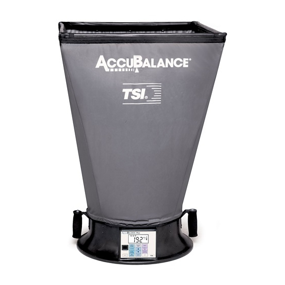
Figure 2. A components ALANCE 1. Hood fabric 2. Base 3. PRINT button in left handle 4. START/HOLD button in right handle Chapter 1... -
Page 17: Keypad
Keypad Figure 3. Electronic meter membrane switch Press to turn the A on and off. ALANCE ON/OFF Press to transmit the displayed flow rate PRINT measurement to the printer or other serial device. Note that the button in the left handle performs the same function. -
Page 18: Display
In the Averaging Mode, press to start a new reading. START/HOLD In the Continuous Reading Mode, press and release to hold the value on display. Press again to resume continuous readings. Note that the button in the right handle performs the same function. Press to switch between the Averaging and the AVG/CONT Continuous Reading Modes. -
Page 19: Preparing The Instrument For Use
Flow units: CFM (cubic feet per minute), l/s (liters per second), and m 3 /hr (cubic meters per hour). The A indicates ALANCE flow already corrected to "standard" conditions (see Appendix A). Flow value: See specifications for range and resolution. Flow direction arrow: Indicates if supply or return air flow calibration is being utilized by the A ALANCE... -
Page 20: An Easy Way To Begin Assembly
To complete the assembly of the 2 ft x 2 ft hood, follow these six steps: Place the base of the A on the floor. ALANCE Lift the top of the fabric. Insert one end of a support pole into its pole mount in the base of the A . -
Page 21: Installing A Support Pole
Grasp the support pole. Bend the pole slightly to insert the top end of the pole into the support pole cup located in the corner of the fabric frame as shown in Figure 6. Figure 6. Installing a support pole Insert the second support pole into the pole mount on the opposite side of the A base. -
Page 22: Display Units
Display Units The A is shipped with cubic feet per minute (CFM) as the ALANCE default flow unit (unless the metric version was ordered). If you wish to change the units to l/s (liters per second) or m 3 /hr (cubic meters per hour), see Changing Dip Switch Settings in Chapter 2 Installing the Batteries The A... -
Page 23: Start Up
Start-Up Press the ON/OFF button on the meter to turn on the power. The display will initially indicate the percent of battery power remaining. During start-up the A performs a self test of its electronic ALANCE functions. If an error is found, an error message will appear on the display. -
Page 24: Selecting Flow Direction
averaging time of six seconds by changing the setting of DIP Switch 6. See Changing DIP Switch Settings in Chapter 2. For more details on the averaging mode, see Chapter 2. Selecting Flow Direction Each A is calibrated for supply and return air separately ALANCE for increased accuracy. -
Page 25: Automatic Shut-Off
display. A new average reading can be initiated by pressing the START/HOLD switch or the button on the right handle. When making a flow measurement, keep objects out of the flow path at the base of the A (one foot clearance minimum). ALANCE However, it is acceptable to have a hand supporting the flow hood at the bottom of the base. - Page 26 Chapter 1...
-
Page 27: Operations In More Detail
Chapter 2 Operations in More Detail This chapter explains how to change fabrics and assemble different hood sizes and presents more detail on the various features of the ALANCE Changing Hoods The A is shipped with a 2 ft x 2 ft hood attached to the ALANCE base. -
Page 28: Assembled 2 Ft X 4 Ft Frame
2 ft x 4 ft Hood To assemble and attach the 2 ft x 4 ft hood, carefully follow these 10 steps: Build the 2 ft x 4 ft frame structure as shown in Figure 7 using six 2 ft aluminum frame tubing pieces, four right-angle tubing connectors, and two straight tubing connectors. - Page 29 Notice: Be sure to press the Velcro surfaces firmly together. When completed, the hood fabric will be stretched fairly taut and will require good bonding of the fabric to the frame. Stretch the cinch belt at the bottom of the fabric over the lip around the top of the molded plastic base of the A ALANCE Align the seams of the fabric panels with the pairs of screw heads...
- Page 30 Figure 8. Installing a support pole Repeat step 7 until all four support poles are installed. Now that the hood is assembled and the fabric is stretched tight, it is a good practice to check the rubber gasket around the top edge of the A fabric.
- Page 31 1 ft x 4 ft Hood To assemble and attach the 1 ft x 4 ft hood, carefully follow these 10 steps: Build the 1 ft x 4 ft frame structure as shown in Figure 9 using four 2 ft aluminum frame tubing pieces, two 1 ft aluminum frame tubing pieces, four right-angle tubing connectors, and two straight tubing connectors.
- Page 32 Build the 1 ft x 5 ft frame structure as shown in Figure 10 using four 2 ft aluminum frame tubing pieces, two 1x tube connectors, two 1 ft aluminum frame tubing pieces, and four right-angle tubing connectors. Remember to construct the frame so that all Velcro surfaces face in (toward the center of the structure).
- Page 33 3 ft x 3 ft Hood To assemble and attach the 3 ft x 3 ft hood, carefully follow these 10 steps: Build the 3 ft x 3 ft frame structure as shown in Figure 11 using four 2 ft aluminum frame tubing pieces, four 1 ft aluminum frame tubing pieces, four right-angle tubing connectors, and four straight tubing connectors.
-
Page 34: Switching On The Power
Switching On the Power The power ON/OFF switch is located on the meter keypad of the . To turn the power on, momentarily press the ON/OFF ALANCE switch. The A will immediately light all display digits ALANCE and sound the buzzer. After a second, the approximate percent of remaining battery life will be displayed. -
Page 35: Continuous Reading Mode
on the keypad. Make sure the arrow is pointing in the direction of the flow before you make a measurement. Continuous Reading Mode In this mode the display is continuously updated either once every second or every other second. The A is shipped with a ALANCE one-second display update rate. -
Page 36: Selecting Flow Units
In the averaging mode, the A takes flow measurements ALANCE for three or six seconds and then displays and holds the time-averaged flow. The averaging time can be changed between three and six seconds by changing DIP switch 6 inside the battery compartment (see Changing DIP Switch Settings later in this chapter). -
Page 37: Changing Dip Switch Settings
(2-second) display rate, you will therefore see less variation in the displayed values. In the averaging mode, you may choose between a three-second and a six-second averaging time period. The A is shipped set ALANCE up in the three-second averaging mode. You can change this by changing the setting of switch 6 in the battery compartment (see Changing DIP Switch Settings). - Page 38 Figure 12. A lying face down ALANCE Remove the battery compartment cover by pulling up on the two latches. You will see the switches numbered 1 through 8 in the corner of the battery compartment. You may wish to remove or tilt up the battery pack to allow easier access to the switches as shown in Figure Chapter 2...
- Page 39 Figure 13. Location of DIP Switches You may change the switch settings using the tip of a ball-point pen, pencil, compass, small screwdriver, or other small, pointed object. Refer to Table 2 for switch settings. Operations in More Detail...
-
Page 40: Low Battery Warning
Table 2. DIP Switch Settings Switch Number Setting: Function Leave in OFF position Leave in OFF position 3 OFF, 4 OFF: Flow units = CFM 3 OFF, 4 ON: Flow units = l/s 3 ON, 4 ON: Flow units = m 3 /hr Leave in OFF position for Rev A thru Rev M Leave in ON position for Rev N and later OFF: 3-second averaging in Averaging Mode... -
Page 41: Connecting The Optional Printer
Connecting the Optional Printer The A can be used with an optional portable printer. The ALANCE printer provides hard copy of selected flow rates and eliminates the awkward task of manually recording flow rates while operating a flow measuring hood. To connect a TSI Model 8925 Portable Printer to the , locate the interface cable that was shipped with the ALANCE printer. - Page 42 Averaging Mode 3 sec Average = 435 CFM 3 sec Average = 1580 m 3 /hr 6 sec Average = 132 l/s ✟ Chapter 2...
-
Page 43: Maintenance
Chapter 3 Maintenance The A is designed for long-term field use. If the ALANCE is used with reasonable care, it should be able to make ALANCE precise measurements over a long time period. Some of the components can be cleaned periodically. When cleaning the components, please follow the instructions given below. -
Page 44: Meter
Frame Kit 1081263 It is recommended that you purchase a frame kit whenever you purchase a hood other than the 2 ft x 2 ft size. The frame kit contains all extra frame tubing and connectors required to build frames for the various size hoods. -
Page 45: Calibration
Figure 14. Flow Sensing Tube Out of Place If you observe the flow sensing taps of the manifold becoming clogged with dust or other material, clean them with a damp cloth. The manifold should be kept in place during cleaning. Do not apply excessive forces on the grid tubes of the manifold. - Page 46 be packed carefully within the A carrying case and then ALANCE inside a proper shipping box, such as the original shipping box. Ship directly to: TSI, Inc. ATTN: Customer Service 500 Cardigan Road Shoreview, MN 55126-3996 ✟ Chapter 3...
-
Page 47: Troubleshooting
Chapter 4 Troubleshooting Table 5 lists the symptoms, possible causes, and recommended solutions for common problems encountered with the A ALANCE If your symptom is not listed, or if none of the solutions solves your problem, please contact TSI. Table 5. Troubleshooting the A ALANCE Symptom Possible Causes... - Page 48 Table 5 (continued) Symptom Possible Causes Corrective Action Sensor grid tubes are Clean the tubes. plugged Reposition the is not ALANCE sealing around ALANCE diffuser form a seal. Flashing flow Trying to read too Flow may not be value "> 0" (Flow high a flow measurable using the is over range)
-
Page 49: Standard Flow Vs. Actual Flow
Appendix A Standard Flow vs. Actual Flow Standard flow is defined as the volumetric flow rate of air at "Standard" temperature and barometric pressure conditions of 70ºF (21.1ºC) and 14.7 psia (760 mmHg). By contrast, actual flow is the volumetric flow rate of air at local temperature and barometric pressure conditions. - Page 50 Example 1: Suppose your air flow temperature is 55ºF and you local barometric pressure is 13.5 psia, and the standard flow indicated on the is 200 (standard) CFM. ALANCE ⎡ ⎤ 14.7 460 + 55 Actual Flow A ctual CFM ⎣...
-
Page 51: Back Pressure
Appendix B Back Pressure It is commonly known that a flow measuring hood may induce a back pressure. In general, back pressures are caused by restrictions in the flow path as well as frictional pressure losses. In order to improve accuracy and sensitivity, all flow measuring hoods incorporate a contracted flow section. -
Page 52: Ccu Balance Serial Interface Connections
Figure 15. Pressure Drop through the A ALANCE If you wish to make back pressure corrections, you must first determine the back pressure correction factor, C b . The back pressure correction factor, C b , can be determined as follows: C b = ---- (8-1) where V and V o are the average air velocities in the duct ahead of the... - Page 53 Appendix C Serial Interface Connections ALANCE A 9-pin cable (Model 8926) is available for use with the A ALANCE and the TSI Model 8925 Portable Printer. This cable allows a direct connection between the A and the printer. Its connections ALANCE are as follows: Signal Name...
- Page 54 Signal Name Computer Signal Name ALANCE tied together pin 1 pin 8 carrier detect tied together pin 2 pin 5 clear to send pin 3 pin 2 transmit data tied together pin 4 pin 6 data set ready transmit data pin 5 pin 3 receive data...
-
Page 55: Return Mode Low Flow Corrections
Appendix D Return Mode Low Flow Corrections The A is calibrated in a vertical position. Thus, in the ALANCE Return Mode, air is flowing up through the A base and ALANCE then through the fabric hood. When using the A in a horizontal orientation at flows ALANCE below 100 CFM (50 l/s), such as at a side wall return vent, the... - Page 56 Appendix D...
-
Page 57: E Specifications
Appendix E Specifications Flow Range 30-2,000 CFM (15-1,000 l/s, 50-3,500 m /hr) ±5% rdg, ±5 CFM (±2.4 l/s, 8.5 m Accuracy /hr) Operating Temperature Range 32-140°F (0-60°C) Weight (using 24 in × 24 in Hood) 7 lb 6 oz (3.4 kg) 24 in ×... - Page 58 Appendix E...
Need help?
Do you have a question about the AccuBalance 8370 and is the answer not in the manual?
Questions and answers