
Related Manuals for Electrolux DC6-4


Summary of Contents for Electrolux DC6-4
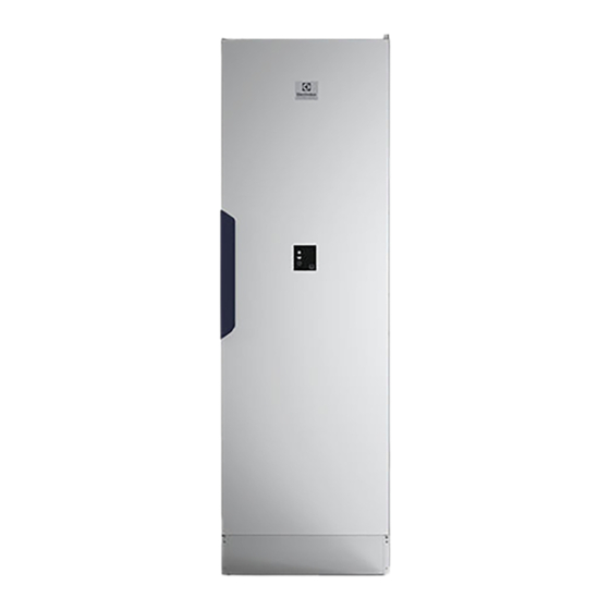
- Page 1 Installation manual Drying Cabinet DC6-4 427001179/EN Original instructions 2022.02.10...
-
Page 3: Table Of Contents
Contents Contents 1 Safety Precautions ..........................5 General safety information......................5 Symbols............................5 2 Technical data.............................6 3 Installation kit ............................7 4 Installation ............................8 Unpacking ..........................8 Recycling instruction for packaging .....................9 Placement ..........................9 Mechanical installation ......................10 5 Evacuation system ..........................11 Fresh air..........................11 Evacuation connection ...................... -
Page 5: Safety Precautions
Installation manual 1 Safety Precautions This appliance can be used in public areas. Remove all objects from pockets such as lighters and matches. WARNING. This appliance is intended only for drying textiles washed in water. DO NOT MODIFY THIS APPLIANCE. Servicing shall be carried out only by authorized personnel. -
Page 6: Technical Data
Installation manual 2 Technical data fig.W01253 Control panel Air outlet* ⌀ 100 mm 1901 1915 1089 * Connected with supplied draft stabilizer and hose. Net weight: 56 kg. -
Page 7: Installation Kit
Installation manual 3 Installation kit E x4 A x1 J x4 F x1 B x1 K x1 G x2 C x1 H x2 D x2 fig.W01507 Draft stabilizer Hose Spigot Fixing screw for spigot Cover plug for adjustable feet Allen key Screw TRX 5x70 zinc-plated Washer N8 5x25 Wall plug... -
Page 8: Installation
Installation manual 4 Installation Place the drying cabinet on its final position. Level the drying cabinet with the adjustable feet. Use the supplied Allen key (A) and adjust all four of the feet through the holes in the base plate of the drying cabinet. Once the drying cabinet is level, press the four cover plugs (B) down firmly into the holes. -
Page 9: Recycling Instruction For Packaging
Installation manual 4.2 Recycling instruction for packaging fig.X02425 Fig. Description Code Type Wrapping film LDPE 4 Plastics Cardboard packaging top PAP 20 Paper Wooden bars FOR 50 Wood Protection film LDPE 4 Plastics Cardboard side protection PAP 20 Paper Wooden bars FOR 50 Wood Support bar... -
Page 10: Mechanical Installation
Installation manual 4.4 Mechanical installation The drying cabinet must be secured to the wall to prevent it from tipping over. (Kit for this included upon delivery.) Once the drying cabinet is in its final position, open the door and slide out the upper hanger section. Drill 8 mm holes in the wall through the two predrilled holes in the rear of the drying cabinet (F). -
Page 11: Evacuation System
Installation manual 5 Evacuation system 5.1 Fresh air When the drying cabinet is running, about 50 m of moist air is evacuated per hour. This air is taken from the room where the drying cabinet is situated. It is therefore important to ensure that fresh air can enter the room from the outside to replace the humid air that is vented out. -
Page 12: Draft Stabilizer
Installation manual 5.2.1 Draft stabilizer The drying cabinet has been tested and set at factory for connection with a draft stabilizer. (Kit for this included upon delivery.) Place the spigot (A) over the hole in the top of the cabinet. Insert the screws and secure the spigot. fig.W01510 Connect the flexible hose (B) to the spigot. -
Page 13: Permanently Installed And Connected To The Ventilation Duct
Installation manual 5.2.2 Permanently installed and connected to the ventilation duct When the drying cabinet is permanently connected to the ventilation duct, the whole room is ventilated through the drying cabinet. (A kit for this is included with the drying cabinet, except for the insert). Place the spigot (A) over the hole in the top of the cabinet. - Page 14 Installation manual If multiple drying cabinets or dryers are connected to the same air duct, a non-return valve must be installed on each appliance to prevent cold air from entering or the air pressure of one appliance affecting the other. fig.W01513 Number of cabinets...
-
Page 15: Reversing The Door
Installation manual 6 Reversing the door Note! The left and right upper hinges are not interchangeable. When rehanging, a new upper hinge must be or- dered from the supplier. Disconnect the power to the appliance. Carefully lay the drying cabinet on its back. Remove the cover on the upper part of the drying cabinet (A) and the protection plate (B) above the control cable from the door’s membrane panel (C). - Page 16 Installation manual Lift up the door a bit from the bottom edge and remove it from the upper hinged joint, far enough so that the hinge pin is exposed. The pin has a groove for the control cable. Pull the door cable (F) with its connecting contact out of the slot in the hinge. The door cable is bared so that it can be pulled through the slot.
- Page 17 Installation manual Remove the cover from the fan unit. The cover is attached with one screw on each short and long side. Move the control cable (K) over to the other side and pull it through the predrilled holes in the side. Reinstall the cover and securely fasten the fan unit again.
- Page 18 Installation manual Attach the door. Insert the door cable through the slot in the new upper hinge. (Use the bared part of the cable). Slide the door up onto the hinge pin. Attach the lower hinge pin. Connect the door cable to the fan unit in the upper part of the drying cabinet using the fast coupling. Make sure the cables are connected in the same way as before.
-
Page 19: Electrical Connection
Installation manual 7 Electrical connection The electrical installation may only be performed by qualified personnel. The drying cabinet is supplied ready for connection with a cable with a grounded plug. Heating options Mains voltage Heat output Total output Recommended fuse Electrically heated 230V 1~ 50/60... -
Page 20: Function Check
Installation manual 8 Function check May only be performed by qualified personnel. A function check must be performed when the installation is finished and before the appliance can be used. Whenever a repair has been made, a function check must be performed before the appliance can be used again. •... -
Page 21: Disposal Information
Installation manual 9 Disposal information 9.1 Disposal of appliance at end of life Before disposing of the machine, make sure to carefully check its physical condition, and in particular any parts of the structure that can give or break during scrapping. The machine’s parts must be disposed of in a differentiated way, according to their different characteristics (e.g. - Page 24 Electrolux Professional AB 341 80 Ljungby, Sweden www.electroluxprofessional.com...
Need help?
Do you have a question about the DC6-4 and is the answer not in the manual?
Questions and answers