
Related Manuals for GW Instek GCT-9040


Summary of Contents for GW Instek GCT-9040
- Page 1 Ground Bond Tester GCT-9040 USER MANUAL GW INSTEK PART NO. 82CT-90400E01 ISO-9001 CERTIFIED MANUFACTURER...
- Page 2 This manual contains proprietary information, which is protected by copyright. All rights are reserved. No part of this manual may be photocopied, reproduced or translated to another language without prior written consent of Good Will company. The information in this manual was correct at the time of printing. However, Good Will continues to improve products and reserves the rights to change specification, equipment, and maintenance procedures at any time without notice.
-
Page 3: Table Of Contents
EXTERNAL CONTROL ............. 74 External Control Overview ....75 REMOTE CONTROL ............81 Interface Configuration ......82 Command Syntax ......... 86 Command List for GCT-9040 ....89 Error Messages ........124 FAQ ................125 APPENDIX ..............127 Fuse Replacement ......127 Error Messages ........ - Page 4 GCT-9040 User Manual INDEX ................134...
-
Page 5: Safety Instructions
SAFETY INSTRUCTIONS AFETY INSTRUCTIONS This chapter contains important safety instructions that you must follow during operation and storage. Read the following before any operation to ensure your safety and to keep the instrument in the best possible condition. Safety Symbols These safety symbols may appear in this manual or on the instrument. - Page 6 (Measurement categories) EN 61010-1:2010 specifies the measurement categories and their requirements as follows. The GCT-9040 does not fall under category II, III or IV. Measurement category IV is for measurement performed at the source of low-voltage installation.
- Page 7 Temperature: 0˚C~40˚C (Pollution Degree) EN 61010-1:2010 specifies the pollution degrees and their requirements as follows. The GCT-9040 falls under degree Pollution refers to “addition of foreign matter, solid, liquid, or gaseous (ionized gases), that may produce a reduction of dielectric strength or surface resistivity”.
- Page 8 GCT-9040 User Manual Power cord for the United Kingdom When using the tester in the United Kingdom, make sure the power cord meets the following safety instructions. NOTE: This lead/appliance must only be wired by competent persons WARNING: THIS APPLIANCE MUST BE EARTHED...
-
Page 9: Getting Started
SENSE L SOURCE H SOURCE L MANU EDIT/SAVE UTILITY GCT-9040 Overview ............10 Introduction to the GCT-9040 ..............10 Main Features ..................11 Accessories ....................11 Package Contents ..................13 Appearance ..............14 Front Panel ....................14 Rear Panel ....................17 Set Up ................ -
Page 10: Gct-9040 Overview
GCT-9040 User Manual GCT-9040 Overview Introduction to the GCT-9040 GCT-9040 is a ground bond tester that can operate as a standalone unit or in conjunction with a GPT-9000 Series safety tester to perform additional ACW/DCW/IR tests before, after or simultaneously(ACW/DCW only) with GB tests. -
Page 11: Main Features
GETTING STARTED Main Features Performance GB: 3A~40A ac Features 100 test conditions (MANU mode) Over temperature, voltage and current protection Pass, Fail, Test, Caution and Ready indicators PWM output (90% efficiency, increased reliability) Interlock (configurable). ... - Page 12 GCT-9040 User Manual Optional Part number Description Accessories GTL-248 GPIB cable GTL-251 GPIB-USB-HS (high speed) Rack Adapter Panel (19”, 4U) GRA-417 Options Part number Description Opt.01 GPIB Interface GPIB card...
-
Page 13: Package Contents
GETTING STARTED Package Contents Check the contents before using the GCT-9040. Opening the box Contents GCT-9040 unit Power cord x1 (region (single unit) dependent) Quick Start guide GTL-215 test leads x1 User manual CD ... -
Page 14: Appearance
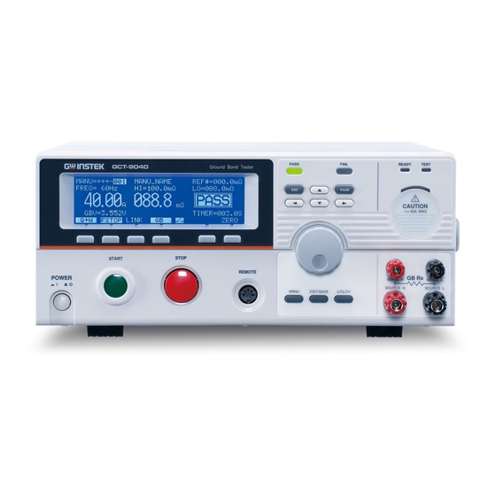
GCT-9040 User Manual Appearance Front Panel PASS/FAIL indicators Display Function keys Directional keys READY indicator TEST indicator PASS FAIL READY TEST GCT-9040 Ground Bond Tester CAUTION PAGE indicator CAUTION 40A MAX. Sense H and L START STOP terminals REMOTE GB Rx... - Page 15 GETTING STARTED READY indicator READY The READY indicator is lit when the tester is ready to begin testing. The STOP button is used to put the tester into READY status. TEST indicator TEST The TEST indicator is lit when a test is on.
- Page 16 GCT-9040 User Manual REMOTE REMOTE The REMOTE terminal is used to terminal connect to a remote controller. STOP STOP button The STOP button is used to stop/cancel tests. The STOP button will also put the tester in the READY status to begin testing.
-
Page 17: Rear Panel
USB A port Used for remote control and firmware updates. LINK LINK port With the GCT-9040 acting as the master unit, the LINK port is used to control a GPT-9XXX slave unit to perform additional ACW, DCW or IR tests. - Page 18 GCT-9040 User Manual Line voltage input Line voltage input: 100/120/220/230VAC ±10% Line voltage fuse Line voltage selector and fuse: 100V/120V T7A 250V 220V/230V T4A 250V GPIB Optional GPIB Optional GPIB interface for remote port control.
-
Page 19: Set Up
GETTING STARTED Set Up Line Voltage Connection and Power Up Background Before powering up the GCT-9040 ensure the correct voltage has been selected on the rear panel. The GCT-9040 supports line voltages of 100V/120V/220V and 230V. Steps Page 127 1. Check the line voltage and the fuse in the fuse holder. - Page 20 GCT-9040 User Manual 5. When the unit is powering up, all the LED indicators will light. Check to make sure all 5 LED indicators are working. 6. Check to make sure the System Self Test passes without errors. E L F...
-
Page 21: Installing The Optional Gpib Card
The optional GPIB is a user-installable option. Follow the instructions below to install the GPIB card. Before installing the optional GPIB card ensure the WARNING GCT-9040 is turned off and disconnected from power. Steps 1. Remove the screws from the rear panel cover plate. -
Page 22: Workplace Precautions
GCT-9040 User Manual Workplace Precautions Background The GCT-9040 is a high current instrument that is capable of delivering up to 40A. The following section describes precautions and procedures that must be followed to ensure a safe work environment. The GCT-9040 generates high current in excess of WARNING 40A. -
Page 23: Operating Precautions
GETTING STARTED Operating Precautions Background The GCT-9040 is a high current instrument. The following section describes precautions and procedures that must be followed to ensure that the tester is operated in a safe manner. The GCT-9040 generates outputs up to 40A ac. - Page 24 GCT-9040 User Manual 5. Ensure the earth ground of the line voltage is properly grounded. 6. Only connect the test leads to the SOURCE H/SENSE H terminals before the start of a test. Keep the test leads disconnected at all other times.
-
Page 25: Operation
OPERATION PERATION Menu Tree ............... 26 Menu Tree Overview ................27 Test Lead Connection ............30 GB Connection ..................30 Grounding Mode Note ................33 GB Manual Testing ............36 Choose/Recall a Manual Test Number ..........37 Edit Manual Test Settings ..............38 Setting the GB Test Current .............. -
Page 26: Menu Tree
Menu Tree This section describes the overall structure of the operation statuses and modes for the GCT-9040 ground bond safety tester. The tester has one testing mode (MANU mode) and 5 main operation statuses (VIEW, EDIT, READY, TEST and STOP). -
Page 27: Menu Tree Overview
OPERATION Menu Tree Overview VIEW status VIEW status is used to view the parameters of the selected manual test. The VIEW status is also used to select the MANU test number. VIEW status is the default state of the unit. VIEW status M A N U = * * * - 0 0 V... - Page 28 GCT-9040 User Manual TEST status TEST status is active when a MANU test is running. Pressing STOP will cancel the test. TEST status M A N U = * * * - 0 0 V F R E Q =...
- Page 29 OPERATION Common Utility This utility controls the LCD, buzzer, interface, Settings control and time settings. These settings are system wide. T I L I T Y L C D t r a s t : L C D g h t R I G L C D B U Z Z...
-
Page 30: Test Lead Connection
GCT-9040 User Manual Test Lead Connection This section describes how to connect the GCT-9040 to a DUT for ground bond testing. The DUT should be floating with respect to ground and should be powered off. GB Connection Background GB tests use the SENSE H/L and SOURCE H/L terminals with the GTL-215 test leads. - Page 31 Steps for GB 1. Turn the power off on the safety tester. Connection 2. Using the GTL-215 GB test lead, (GCT-9040) a. Connect the Sense H lead to the SENSE H terminal. b. Connect the Sense L lead to the SENSE L terminal.
- Page 32 GCT-9040 User Manual Steps for 1. Turn the power off on the GPT-9XXX safety ACW/DCW/IR tester. Connection 2. Using the GHT-114 test leads, (GPT-9XXX) a. Connect the high voltage test lead(red) to the HIGH VOLTAGE terminal and screw firmly into place.
-
Page 33: Grounding Mode Note
Live or neutral pin from power cord or socket. Grounding Mode Note Background The GCT-9040 operates with the SOURCE L terminal floating with respect to the earth ground. For the GCT-9040 and GPT-9XXX Series, this is referred to as having the GROUND MODE is set to OFF. - Page 34 GCT-9040 User Manual Overview GROUND MODE = OFF This mode is for DUTs that are floating and not directly connected to an earth ground. When GROUND MODE is set to OFF any stray capacitance/resistance that leaks to the earth ground from the DUT side of the testing circuit are not measured.
- Page 35 OPERATION The GCT-9040 is a floating device. The DUT Warning ground mode setup depends on the GPT-9XXX ground mode setting. GCT-9040 (GB tests) GPT-9XXX (ACW/DCW) Source H High Voltage terminal Sense H Sense L Return terminal Source L GROUND MODE = OFF...
-
Page 36: Gb Manual Testing
PASS / FAIL MANU Test → from page 51. Zeroing of the Test Leads → from page 54 Before operating the GCT-9040 please read the safety precautions as outlined in the Set Up chapter on page 19. -
Page 37: Choose/Recall A Manual Test Number
OPERATION Choose/Recall a Manual Test Number Background Up to 100 different manual tests can be saved/recalled. MANU tests are selected in the VIEW status. Steps 1. Ensure that the tester is in VIEW status. See the menu tree on page 26 for details on how to enter the VIEW status. -
Page 38: Edit Manual Test Settings
GCT-9040 User Manual Edit Manual Test Settings Background To edit any of the manual test settings, the tester must be in EDIT status. Any settings or parameters that are edited only apply to the currently selected MANU number. Steps EDIT/SAVE 1. -
Page 39: Setting The Gb Test Current
OPERATION Setting the GB Test Current Background The GB test current can be set from 3A to 40A Steps 1. Ensure the tester is in EDIT status. Page 38 2. Press the UP / DOWN arrow keys to bring the cursor to the current setting. -
Page 40: Setting The Upper And Lower Limits
GCT-9040 User Manual 2. Press the UP / DOWN arrow keys to bring the cursor to the FREQ setting. M A N U = * * * - 0 0 0 0 V F R E Q = 0 H z 1 0 00 G B V = 0 . - Page 41 OPERATION Toggling the HI/LO units will also toggle the REF# Note units as well (REF# mΩ, REF# V). The REF# units and the HI/LO units are the same. If the units are changed, the REF# value will need to be set again. See page 42 for setting the REF# value.
-
Page 42: Setting A Reference Value
GCT-9040 User Manual Setting a Reference Value Background The REF# acts as an offset. The REF# value is subtracted from the measured current (ACW, DCW) or measured resistance (IR, GB). Steps 1. Ensure the tester is in EDIT status. Page 38 2. -
Page 43: Setting The Test Time (Timer)
OPERATION Example: Ω units REF# . 0 m Ω M A N U = * * * - 0 0 m Ω Ω F R E Q = 0 H z 1 0 00 m Ω G B V = 5 . 2 0 0 V = 0 0 1 . -
Page 44: Creating A Manu Test File Name
GCT-9040 User Manual 2. Press the TIMER soft-key or use I M E the UP/DOWN arrow keys to bring the cursor to the TIMER setting. M A N U = * * * - 0 0 0 0 V F R E Q =... -
Page 45: Saving And Exiting Edit Status
OPERATION 2. Use the UP/DOWN arrow keys to bring the cursor to the MANU test file name at the top of the screen. The test file name is initially set as MANU_NAME. cursor M A N U = * * * - 0 0 0 0 V F R E Q = 0 H z... - Page 46 GCT-9040 User Manual M A N U = * * * - 0 0 V F R E Q = 0 H z 1 0 00 Ω G B R = A M P 0 0 . 1 S = 0 0 1 . 0 S...
-
Page 47: Running A Manu Test
OPERATION Running a MANU Test Background A test can be run when the tester is in READY status. The tester cannot start to run a test under the Note following conditions: A protection setting has been tripped; when a protection setting has been tripped the corresponding error message is displayed on the screen. - Page 48 GCT-9040 User Manual STOP 2. Press the STOP button to put the tester into the READY status. READY status M A N U = * * * - 0 0 V F R E Q = 0 H z 1 0 00 Ω...
- Page 49 OPERATION Measured Ω/V Test Current TEST status M A N U = * * * - 0 0 V F R E Q = 0 H z 1 0 00 0 051 Ω G B R = 0 0 5 . 1 m A M P 0 0 .
- Page 50 GCT-9040 User Manual M A N U = * * * - 0 0 V F R E Q = 0 H z 1 0 00 Ω G B R = A M P 0 0 . 1 S = 0 0 1 . 0 S...
-
Page 51: Pass / Fail Manu Test
OPERATION PASS / FAIL MANU Test Background If the test is allowed to run to completion (the test is not stopped or a protection setting is not tripped) then the tester will judge the test as either PASS or FAIL. The test will be judged PASS when: Note ... - Page 52 GCT-9040 User Manual START Pressing the START button will restart the test. The buzzer will only sound if the Pass Sound is set Note to ON. See page 67 for buzzer details. The START button is disabled when the buzzer is beeping.
- Page 53 OPERATION M A N U = * * * - 0 0 V F R E Q = 0 H z 1 0 00 0 051 Ω G B R = 0 0 5 . 1 m A M P 0 0 .
-
Page 54: Zeroing Of The Test Leads
GCT-9040 User Manual Zeroing of the Test Leads Background The Zeroing function is used to determine the resistance of the test leads for GB tests. When a zero check is performed, the reference is automatically set to the measured resistance of the test leads. - Page 55 OPERATION 4. The ZERO function can be E R O activated by pressing the corresponding soft-key in the READY status. The ZERO soft-key will be highlighted. START 5. Press the START button to perform the zero check. The tester will go into the ZERO status.
- Page 56 GCT-9040 User Manual I<SET If SOURCE H/L terminals are open or poorly connected, then an I<SET error will appear on the screen. Stop the test and re-check the connection again and try again. I<SET error message FAIL status M A N U = * * * -...
-
Page 57: Linked Acw/Dcw/Ir Tests
GB test. IR tests can only be performed before or after a GB test. The LINK port on the GCT-9040 is used to control the linked slave unit. The slave unit can be used in MANU or AUTO mode, depending on the setup. -
Page 58: Link Connection
RS-232, with a baud of 115200. Steps 1. Ensure the power is off on both the GCT-9040 and the GPT-9XXX slave unit. 2. Connect the LINK cable (GTL-132) to the LINK port on the GCT-9040 and to the RS-232 port on the GPT-9XXX unit. - Page 59 OPERATION No more than 2 units should be stacked vertically. Note...
-
Page 60: Link Test Configuration
2. The GCT-9040 will be in VIEW mode upon startup. *The GCT-9040 will perform a search to see if a Note slave unit is connected with the LINK cable upon startup. If the slave GPT-9XXX is found then the LINK connection will automatically be activated at startup. - Page 61 Hold the MANU/AUTO key to select an AUTO test. Use the scroll wheel to select the desired MANU or AUTO test. I N K 6. Press the LINK soft-key on the GCT-9040 if the LINK connection is not already activated.
- Page 62 C O N I N K The GPT-9XXX will enter the RMT-VIEW mode if it wasn’t already. 7. On the GCT-9040 press the F1 soft- G + W key to toggle the order of the testing mode: GB then ACW/DCW/IR test.
-
Page 63: Run Link Test
(from the VIEW status). START 2. Press the START button on the GCT-9040 to start the LINK tests. TEST will be displayed on the screen of the GCT-9040 or GPT- 9XXX when a particular test is... - Page 64 GCT-9040 User Manual GCT-9040 (GB) Test Example: M A N U = * * * - 0 0 V F R E Q = 0 H z 1 0 00 0 051 Ω G B R = 0 0 5 . 1 m A M P 0 0 .
- Page 65 Note are locked when the tester has been stopped. All the results up until when the test was stopped are shown on-screen; GB results on the GCT-9040 screen, ACW/DCW/IR results on the GPT-9XXX slave unit. Please see page 51 to see the PASS/FAIL details for GB tests.
-
Page 66: Common Utility Settings
GCT-9040 User Manual Common Utility Settings The Common Utility settings are system-wide settings that apply to all the MANU tests. The Common Utility menu includes the following settings: LCD Settings → from page 66. Buzzer Settings → from page 67. - Page 67 OPERATION 5. Use the scroll wheel to select a parameter for the chosen menu item. LCD Contrast 1(low) ~ 8(high) LCD Brightness BRIGHT, DARK EDIT/SAVE 6. Press EDIT/SAVE to save the settings and exit to VIEW status. The ESC key can be pressed at any time to cancel Note and exit back to VIEW status.
- Page 68 GCT-9040 User Manual 4. Use the UP/DOWN arrow keys to choose a menu item: Pass Sound or Fail Sound. 5. Use the scroll wheel to select a parameter for the chosen menu item. Pass Sound ON (000.2s~999.9s), OFF Fail Sound ON (000.2s~999.9s), OFF...
- Page 69 OPERATION T I L I T Y I n t f a c U S B 1 1 5 2 0 L C D B U Z Z N T E C T R L T I M E By default the interface is fixed to USB with a baud Note of 115200 when the GPIB interface is not installed.
- Page 70 GCT-9040 User Manual Control Settings Description The Control settings are accessed in the COMMON UTILITY menu. The Control settings include: Start Control, Double Action, Key Lock and Interlock. Start Control is used to determine how a test is started. Tests can be started via the front panel (START/STOP buttons), from a remote controller or via the SIGNAL I/O port.
- Page 71 ON, OFF Key Lock INTERLOCK ON, OFF EDIT/SAVE 6. Press EDIT/SAVE to save the settings and exit to VIEW status. The Double Action setting is ignored when the Note GCT-9040 is being controlled remotely using the USB or GPIB interfaces.
- Page 72 GCT-9040 User Manual If a test is started with INTERLOCK ON, but the Note interlock signal I/O pins are not shorted (either with the included interlock key or manually), the INTERLOCK OPEN message will be displayed, preventing the test from starting.
- Page 73 OPERATION UTILITY 2. Press the UTILITY key. 3. Press the TIME soft-key to bring T I M E up the Time Common Utility menu. T I L I T Y S I G T I M E 0 0 0 . 1 L C D B U Z Z N T E...
-
Page 74: External Control
GCT-9040 User Manual XTERNAL CONTROL The External Control chapter covers the REMOTE terminal and the SIGNAL I/O port. External Control Overview ..........75 Remote Terminal Overview ..............75 Remote Controller Operation ..............76 SIGNAL I/O Overview ................77 Using the SIGNAL I/O to Start/Stop Tests ......... 79... -
Page 75: External Control Overview
EXTERNAL CONTROL External Control Overview The External Control section describes the front panel REMOTE terminal connection and the rear panel SIGNAL I/O port. Remote Terminal Overview Overview The REMOTE terminal connector is a standard 5-pin DIN terminal suitable for a remote controller. -
Page 76: Remote Controller Operation
3. The tester will now only be able to start a test using a remote controller. Even if the GCT-9040 is configured to use the NOTE REMOTE CONNECT option, the STOP button on the front panel can still be used to stop a test. -
Page 77: Signal I/O Overview
EXTERNAL CONTROL SIGNAL I/O Overview Overview The SIGNAL I/O port can be used to remotely start/stop tests and monitor the test status of the instrument. The SIGNAL I/O port is also used for the interlock function (page 70). The SIGNAL I/O port uses a DB-9 pin female connector. - Page 78 GCT-9040 User Manual Output PIN 6 OUTPUT_TEST Connection PIN 7 OUTPUT_FAIL PIN 8 OUTPUT_PASS PIN 9 OUTPUT_COM Input Signals Signal Properties High level input voltage 5V ~ 32V Low level input voltage 0V ~ 1V Low level input current Maximum of -5mA...
-
Page 79: Using The Signal I/O To Start/Stop Tests
5. To stop the testing, temporarily short the INPUT_STOP and INPUT_COM line again. Even if the GCT-9040 is configured to use the NOTE SIGNAL I/O interface, the STOP button on the front panel can still be used to stop a test. -
Page 80: Using The Interlock Key
GCT-9040 User Manual Using the Interlock Key Background When the INTERLOCK function is set to ON, tests are only allowed to start when both Interlock pins on the signal I/O port are shorted. Using the Interlock key will short the INTERLOCK1 and INTERLOCK2 pins on the signal I/O port. -
Page 81: Remote Control
REMOTE CONTROL EMOTE CONTROL This chapter describes basic configuration of IEEE488.2 based remote control. The remote interface supports USB and GPIB. Interface Configuration ........... 82 Command Syntax ............86 Command List ..............89 Error Messages .............. 124... -
Page 82: Interface Configuration
GCT-9040 User Manual Interface Configuration USB Remote Interface Type A, host PC side Configuration connector Rear panel Type A GCT-9040 side connector CDC (communications device USB Class class) (VCP, Virtual Com Port) Panel operation 1. Connect the USB cable to the rear panel USB A port. - Page 83 Sound → Device Manager. Run this query command via the terminal after the instrument has been configured for USB remote control (page 82). *idn? This should return the Model number, Serial number, and Firmware version in the following format: GCT-9040, XXXXXXXXXXXX, V1.00...
- Page 84 GCT-9040 User Manual Model number : GCT-9040 Serial number :12 character serial number Firmware version : V1.00 Display When the panel is being remotely controlled via the USB or GPIB interfaces, RMT will be displayed on the screen. M A N U = * * * -...
- Page 85 REMOTE CONTROL To put the tester back to RMT, simply issue another Note remote control command.
-
Page 86: Command Syntax
GCT-9040 User Manual Command Syntax Partial compatibility IEEE488.2 Compatible Partial compatibility Standard SCPI, 1999 Command SCPI commands follow a tree-like structure, Structure organized into nodes. Each level of the command tree is a node. Each keyword in an SCPI command represents each node in the command tree. - Page 87 REMOTE CONTROL Query A query is a simple or compound command followed by a question mark (?). A parameter (data) is returned. Example MANU1:ACW:VOLTage? Command Forms Commands and queries have two different forms, long and short. The command syntax is written with the short form of the command in capitals and the remainder (long form) in lower case.
- Page 88 GCT-9040 User Manual <NR3> floating point 4.5e-1, 8.25e+1 <NRf> any of NR1, 2, 3 1, 1.5, 4.5e-1 <string> ASCII text TEST_NAME string Message CR, LF Carriage Return, Line feed code Terminator...
-
Page 89: Command List For Gct-9040
REMOTE CONTROL Command List for GCT-9040 System SYSTem:LCD:CONTrast ........... 91 Commands SYSTem:LCD:BRIGhtness ......... 91 SYSTem:BUZZer:PSOUND ........92 SYSTem:BUZZer:FSOUND ........92 SYSTem:BUZZer:PTIMe ..........92 SYSTem:BUZZer:FTIMe ..........93 SYSTem:ERRor ............93 SYSTem1:ERRor............94 SYSTem:GPIB:VERSion ..........95 Function FUNCtion:TEST ............96 Commands FUNCtion1:TEST ............97 MEASure<x>............... - Page 90 GCT-9040 User Manual MANU1:IR:RHISet ........... 111 MANU1:IR:RLOSet ..........111 MANU1:IR:TTIMe ........... 112 MANU1:IR:REF ............112 MANU:GB:CUTMode ..........113 MANU:GB:CURRent ..........113 MANU:GB:RHISet ........... 114 MANU:GB:RLOSet ..........114 MANU:GB:VHISet ........... 115 MANU:GB:VLOSet ..........115 MANU:GB:TTIMe ............ 116 MANU:GB:FREQuency ........... 116 MANU:GB:REF ............117 MANU:GB:ZEROCHECK ........
-
Page 91: System System:lcd:contrast
REMOTE CONTROL System Commands SYSTem:LCD:CONTrast ................ 91 SYSTem:LCD:BRIGhtness ..............91 SYSTem:BUZZer:PSOUND ..............92 SYSTem:BUZZer:FSOUND ..............92 SYSTem:BUZZer:PTIMe ................. 92 SYSTem:BUZZer:FTIMe ................. 93 SYSTem:ERRor ..................93 SYSTem1:ERRor ..................94 SYSTem:GPIB:VERSion ................95 SYSTem:LCD:CONTrast Query Description Sets the contrast of the LCD display from 1 (low) to 8 (bright). -
Page 92: System:buzzer:psound
GCT-9040 User Manual Example SYST:LCD:BRIG 2 Sets the display brightness to bright. SYSTem:BUZZer:PSOUND Query Description Turns the buzzer sound on or off for a PASS judgment. Syntax SYSTem:BUZZer:PSOUND{ON|OFF} Query Syntax SYSTem:BUZZer:PSOUND ? Parameter/ PASS Sound on. Return parameter PASS Sound off. -
Page 93: System:buzzer:ftime
Sets the buzzer to 1 second for a FAIL judgment. SYSTem:ERRor Query Description Returns any errors in the output buffer for the GCT-9040. See the error code table below for details. Query Syntax SYSTem:ERRor ? Return parameter <string> Returns an error string that includes an error code and an error description. -
Page 94: System1:Error
GCT-9040 User Manual 37,Frequency Setting Error 40,TEST Time Setting Error 41, LINK Setting Error (LINK GPT-9800/9900 Error) 42, Voltage HISet Error (GCT-9040 CUT V HI SET Error) 43, Voltage LOSet Error (GCT-9040 CUT V LO SET Error) 45, Buffer Error (Command buffer overflow) -
Page 95: System:gpib:version
REMOTE CONTROL 34,Resistance HI SET Error 35,Resistance LO SET Error 36,REF Setting Error 37,Frequency Setting Error 38,ARC Setting Error 39,RAMP Time Setting Error 40,TEST Time Setting Error 45,Buffer Error 60,Get Data = 0 (GPT-9900 only get SWEEP Data) Example SYST1:ERR ? >0,No Error Returns “0,No Error”... -
Page 96: Function Function:test
Query Description Turns the currently selected test (output) on or off for the GCT-9040. If a slave is connected using the LINK cable, its output will also turn on, according to the order of the test settings (G-W, W-G, G+W). -
Page 97: Commands Function1:Test
Description Returns the test parameters & results of the tester. MANU mode: Returns the test parameters & results of a MANU test for both the GCT-9040 and the slave, if connected. AUTO mode: Returns the test parameters & results of the selected step (1-16) of the AUTO test of the slave, if connected. -
Page 98: Main1:Function
<NR1>1~16. Step number. (AUTO mode) Return parameter <string>LN Returns a string with the test <string> status of the GCT-9040 test, followed by another string of the slave test, if connected, in the following format: function, judgment or status, test voltage, test current or resistance,... - Page 99 REMOTE CONTROL Parameter/ MANU Puts the tester mode to MANU. Return parameter AUTO Puts the tester mode to AUTO. Example MAIN1:FUNC MANU Sets the tester to MANU mode for the slave unit.
- Page 100 GCT-9040 User Manual Manual Commands MANU:STEP ................... 101 MANU1:STEP ..................101 MANU:NAME ..................101 MANU1:RTIMe ..................102 MANU1:EDIT:MODE ................102 MANU1:ACW:VOLTage ..............103 MANU1:ACW:CHISet ................103 MANU1:ACW:CLOSet ................104 MANU1:ACW:TTIMe ................105 MANU1:ACW:FREQuency ..............105 MANU1:ACW:REF ................106 MANU1:ACW:ARCCurrent ..............106 MANU1:DCW:VOLTage ..............
-
Page 101: Manu:step
REMOTE CONTROL MANU1:UTILity:MAXHold ..............119 MANU1:UTILity:GROUNDMODE ............ 119 MANU<x>:EDIT:SHOW ..............120 TESTok:RETurn ..................120 MANU:STEP Query Description Sets the MANU test number for the GCT-9040. Syntax MANU:STEP <NR1> Query Syntax MANU:STEP? Parameter/ <NR1> 0~100. Return parameter Example MANU:STEP 100 Sets the manual test number to 100. -
Page 102: Manu1:Rtime
GCT-9040 User Manual Syntax MANU:NAME <string> Query Syntax MANU:NAME? Parameter/ <string> 10 character string. (first character must Return parameter be a letter) Example MANU:NAME test1 Sets the manual test name to “test1”. MANU1:RTIMe Query Description Sets or returns the Ramp Time for the test in seconds for the slave unit when in LINK mode. -
Page 103: Manu1:Acw:voltage
REMOTE CONTROL Example MANU1:EDIT:MODE ACW Sets the mode to ACW for the slave unit. MANU1:ACW:VOLTage Query Description Sets or returns the ACW voltage in kV for the slave unit when in LINK mode. The test must first be in ACW mode before this command can be used. Syntax MANU1:ACW:VOLTage <NR2>... -
Page 104: Manu1:Acw:closet
GCT-9040 User Manual MANU1:ACW:CLOSet Query Description Sets or returns the ACW LO SET current value in milliamps for the slave unit when in LINK mode. The LO SET value must be less than the HI SET value. The test must first be in ACW mode before this command can be used. -
Page 105: Manu1:Acw:ttime
REMOTE CONTROL MANU1:ACW:TTIMe Query Description Sets or returns the ACW test time in seconds for the slave unit when in LINK mode. The test must first be in ACW mode before this command can be used. Note: A “TIME ERR” will result if the Ramp Time + Test Time is ≥... -
Page 106: Manu1:Acw:ref
GCT-9040 User Manual Example MANU1:ACW:FREQ 50 Sets the ACW test frequency to 50Hz for the slave unit. MANU1:ACW:REF Query Description Sets or returns the ACW reference value in mA for the slave unit. The test must first be in ACW mode before this command can be used. -
Page 107: Manu1:Dcw:voltage
REMOTE CONTROL Example MANU1:ACW:ARCC 0.04 Sets the ACW ARC value to 0.04 mA for the slave unit. MANU1:DCW:VOLTage Query Description Sets or returns the DCW voltage in kV for the slave unit. The test must first be in DCW mode before this command can be used. -
Page 108: Manu1:Dcw:closet
GCT-9040 User Manual Parameter/ <NR2> 0.001 ~ 011.0 (GPT-98XX) Return parameter 0.001 ~ 021.0 (GPT-99XX/99XXA) Example MANU1:DCW:CHIS 5 Sets the DCW HI SET current to 5mA. MANU1:DCW:CLOSet Query Description Sets or returns the DCW LO SET current value in milliamps for the slave unit when in LINK mode. -
Page 109: Manu1:Dcw:ttime
REMOTE CONTROL MANU1:DCW:TTIMe Query Description Sets or returns the DCW test time in seconds for the slave unit when in LINK mode. The test must first be in DCW mode before this command can be used. In special MANU mode, the TIMER can be turned off. -
Page 110: Manu1:Dcw:arccurrent
GCT-9040 User Manual MANU1:DCW:ARCCurrent Query Description Sets or returns the DCW ARC current value in mA for the slave unit when in LINK mode. ARC must be enabled to set the ARC current. The test must first be in DCW mode before this command can be used. -
Page 111: Manu1:Ir:rhiset
REMOTE CONTROL MANU1:IR:RHISet Query Description Sets or returns the IR HI SET resistance value in MΩ (GPT-98XX) or GΩ for the slave unit when in LINK mode. The test must first be in IR mode before this command can be used. Syntax MANU1:IR:RHISet <NR1>|NULL Query Syntax... -
Page 112: Manu1:Ir:ttime
GCT-9040 User Manual Parameter/ <NR1> GPT-98XX only: Return parameter 1 ~ 9999 (unit = MΩ) GPT-99XX/GPT-99XXA only: Format A: 0.001 ~ 50.00 (unit = GΩ) Format B: 0.001G ~ 50.00G Format C: 1M ~ 50000M Example MANU1:IR:RLOS 10 (GPT-98XX) Sets the IR LO SET resistance to 10MΩ for the slave unit. -
Page 113: Manu:gb:cutmode
REMOTE CONTROL Parameter/ <NR1> GPT-98XX only: Return parameter 0000 ~ 9999 (unit = MΩ) GPT-99XX/GPT-99XXA only: Format A: 0 ~ 50.00 (unit = GΩ) Format B: 0G ~ 50.00G Format C: 0M ~ 50000M Example MANU1:IR:REF 900 (GPT-98XX) Sets the IR reference to 900 MΩ for the slave unit. Example MANU1:IR:REF 0.900 (GPT-99XX/... -
Page 114: Manu:gb:rhiset
GCT-9040 User Manual Syntax MANU:GB:CURRent <NR2> Query Syntax MANU:GB:CURRent? Parameter/ <NR2> 3.00~40.00 Return parameter Example MANU:GB:CURR 3.00 Sets the GB current to 3.00A. MANU:GB:RHISet Query Description Sets or returns the GB HI SET resistance value in mΩ. The test must first be in GB mode and the... -
Page 115: Manu:gb:vhiset
REMOTE CONTROL Parameter/ <NR2> 0.000 ~ 649.9 Return parameter Example MANU:GB:RLOS 50 Sets the GB LO SET resistance to 50mΩ. MANU:GB:VHISet Query Description Sets or returns the GB HI SET voltage value in V. The test must first be in GB mode and the cutoff mode must be set to CUT_V (see the MANU:GB:CUTMode command) before this command can be used. -
Page 116: Manu:gb:ttime
GCT-9040 User Manual Example MANU:GB:VLOS 1.000 Sets the GB LO SET voltage to 1V. MANU:GB:TTIMe Query Description Sets or returns the GB test time in seconds. The test must first be in GB mode before this command can be used. -
Page 117: Manu:gb:ref
REMOTE CONTROL MANU:GB:REF Query Sets or returns the GB reference value in mΩ. The Description test must first be in GB mode before this command can be used. The GB reference value must be less than the HI SET value. Syntax MANU:GB:REF <NR2>... -
Page 118: Manu1:Utility:arcmode
GCT-9040 User Manual MANU1:UTILity:ARCMode Query Description Sets or returns the ARC mode status for the current test of the slave unit when in LINK mode. The ARC mode cannot be set for the IR and GB function. Syntax MANU1:UTILity:ARCMode {OFF|ON_CONT|... -
Page 119: Manu1:Utility:maxhold
REMOTE CONTROL Parameter/ CONT Sets/returns the fail mode as continue. Return parameter HOLD Sets/returns the fail mode as hold. STOP Sets/returns the fail mode as stop. Example MANU1:UTIL:FAIL CONT Sets the fail mode to CONT (continue) for the slave unit. MANU1:UTILity:MAXHold Query Description... -
Page 120: Manu
GCT-9040 User Manual MANU<x>:EDIT:SHOW Query Description Returns the test parameters of a selected manual test for the GCT-9040. Query Syntax MANU<x>:EDIT:SHOW? Parameter/ <x> <NR1> 000~100. Manual test number Return parameter <string> Returns a string in the following format: Test function, test voltage, HI SET value, LO SET value, Ramp time, test time.:Edit:show -
Page 121: Cls
Query Syntax *IDN? Return parameter <string> Returns the instrument identification as a string in the following format: GCT-9040,XXXXXXXXXXXX,V1.00 Model number : GCT-9040 Serial number :12 character serial number Firmware version : V1.00 *IDN1 Query Description Queries the model number, serial number, and firmware version of the slave unit when in LINK mode. - Page 122 GCT-9040 User Manual Return parameter <string> Returns the instrument identification as a string in the following format: GPT-9803,XXXXXXXXXXXX,V1.00 Model number : GPT-9803 Serial number :12 character serial number Firmware version : V1.00...
-
Page 123: Rmtoff
InterLock Key Open Description This special function is not a command. When in remote mode, the GCT-9040 will send the message, “InterLock Key Open” if a test is started with INTERLOCK set to ON, but the interlock signal I/O pins are not shorted (either with the included interlock key or manually). -
Page 124: Error Messages
GCT-9040 User Manual Error Messages Background The possible error messages returned from SYST:ERR? or SYST1:ERR queries are listed below. Error Error Code Command Error 0x14 Value Setting Error 0x15 String Setting Error 0x16 Query Error 0x17 MODE Setting Error 0x18... -
Page 125: Faq
• The tester will not turn on. • The panel keys are not working. • When I press the START button the tester will not start testing? • The accuracy does not match the specification. The tester will not turn on. Ensure the power cord is connected. - Page 126 GCT-9040 User Manual If “Interlock” is enabled, the interlock key must be inserted into the signal I/O port on the rear before a test can be started. See page 80 for details. Lastly, ensure that the Start Ctrl setting is correctly configured in the Common Utility menu.
-
Page 127: Appendix
APPENDIX PPENDIX Fuse Replacement Steps 1. Turn the instrument POWER off. 2. Remove the power cord. 3. Remove the fuse socket using a flat screwdriver. 4. Replace the fuse in the fuse holder. 5. Ensure the correct line voltage is lined up with the arrow on the fuse holder. -
Page 128: Error Messages
System Self Test The following error messages or messages may appear on the GCT- 9040 screen during the Start-Up initialization. If any of these error messages appear on the unit, please see an authorized GW Instek distributor. Error Messages Description... - Page 129 APPENDIX Test Errors The following error messages or messages may appear on the GCT screen when configuring or running tests. Error Messages Description SHORT Voltage is too low or there is no High Voltage output. Indicates that the DUT could be shorted.
-
Page 130: Gct-9040 Specifications
GCT-9040 User Manual GCT-9040 Specifications The specifications apply when the GCT-9040 is powered on for at least 30 minutes at 15˚C~35˚C. Specifications Environment Range Temperature Humidity ≤70% (No Warranty 15˚C ~ 35˚C condensation) ≤70% (No Operation 0˚C ~ 40˚C condensation) ≤85% (No... -
Page 131: Gct-9040 Dimensions
Power Consumption: Max 700VA Dimensions & Weight 330(W) x 148(H) x 460(D) mm (Max.) Approximately 17kg max Memory Single Step Memory (MANU: 100 blocks) Table 1: Output Limitation in GCT-9040 Upper Current Pause Output Time 20A<I≤40A At least as long 999.9... - Page 132 GCT-9040 User Manual GCT-9040 Dimensions 395.9 PASS FAIL READY TEST GCT-9040 Ground Bond Tester PAGE CAUTION 40A MAX. START STOP REMOTE GB Rx POWER SENSE H SENSE L SOURCE H SOURCE L MANU EDIT/SAVE UTILITY 322.0 458.7 329.7...
-
Page 133: Declaration Of Conformity
No. 69 Lushan Road, Suzhou New District Jiangsu, China. declare that the below mentioned product Type of Product: Electrical Safety Tester Model Number: GCT-9040 are herewith confirmed to comply with the requirements set out in the Council Directive on the Approximation of the Law of Member States relating to Electromagnetic Compatibility (2004/108/EC &... - Page 134 GCT-9040 User Manual NDEX GB ............ 36 Accessories ......... 11 ground mode ......... 33 Caution symbol......5 results ..........51 Cleaning the instrument ..... 7 running a test ........ 47 Declaration of conformity ..133 saving ..........45 Dimensions ....... 132 test filename ........
- Page 135 INDEX GPIB ..........68 USB ..........68 interface .......... 68 Warning symbol ......5 key lock .......... 70 Workplace precautions ..... 22 LCD ..........66 Zeroing ........54 Signal I/O Time ......72 start control........70...
Need help?
Do you have a question about the GCT-9040 and is the answer not in the manual?
Questions and answers