Table of Contents
Advertisement
Quick Links
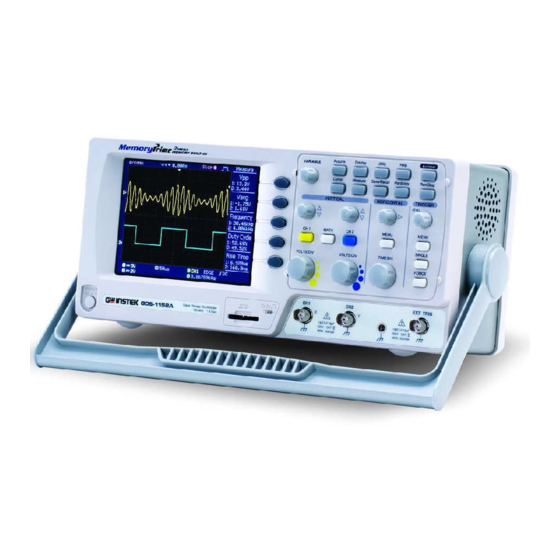
Digital Storage Oscilloscope
GDS-1000A Series
USER MANUAL
GW INSTEK PART NO. 82DS-1102AMA1
ISO-9001 CERTIFIED MANUFACTURER
July 2009 edition
This manual contains proprietary information, which is protected by
copyright. All rights are reserved. No part of this manual may be
photocopied, reproduced or translated to another language without
prior written consent of Good Will Corporation.
The information in this manual was correct at the time of printing.
However, Good Will continues to improve its products and therefore
reserves the right to change the specifications, equipment, and
maintenance procedures at any time without notice.
Good Will Instrument Co., Ltd.
No. 7-1, Jhongsing Rd., Tucheng City, Taipei County 236, Taiwan.
Advertisement
Table of Contents

Related Manuals for GW Instek GDS-1062A


Summary of Contents for GW Instek GDS-1062A
-
Page 1: Digital Storage Oscilloscope
Digital Storage Oscilloscope GDS-1000A Series USER MANUAL GW INSTEK PART NO. 82DS-1102AMA1 July 2009 edition This manual contains proprietary information, which is protected by copyright. All rights are reserved. No part of this manual may be photocopied, reproduced or translated to another language without prior written consent of Good Will Corporation. -
Page 2: Table Of Contents
TABLE OF CONTENTS GDS-1000A Series User Manual Trigger key 3/6 ............... 34 Trigger key 4/6 ............... 35 Table of Contents Trigger key 5/6 ............... 35 Trigger key 6/6 ............... 36 Utility key 1/4 ................. 36 ... - Page 3 Setup file format ..............90 Probe Specifications ............121 Using the SD card file utilities ..........91 GDS-1062A/1102A/1152A Probe........121 Quick Save (HardCopy) ............. 94 EC Declaration of Conformity .......... 122 Save .................. 96 File type/source/destination ..........96 INDEX ............
-
Page 4: Safety Instructions
SAFETY INSTRUCTIONS GDS-1000A Series User Manual Safety Guidelines Make sure the BNC input voltage does not General AFETY INSTRUCTIONS exceed 300V peak. Guideline Never connect a hazardous live voltage to the CAUTION ground side of the BNC connectors. It might This chapter contains important safety instructions lead to fire and electric shock. -
Page 5: Power Cord For The United Kingdom
SAFETY INSTRUCTIONS GDS-1000A Series User Manual Fuse type: T1A/250V Location: Indoor Fuse Storage environment To ensure fire protection, replace the fuse only Relative Humidity: < 85% WARNING with the specified type and rating. Temperature: -10°C to 60°C ... -
Page 6: Getting Started
* firmware V1.5. Main Features Model name Frequency bandwidth Input channels GDS-1062A DC – 60MHz (–3dB) GDS-1102A DC – 100MHz (–3dB) GDS-1152A DC – 150MHz (–3dB) 1 GS/s real-time sampling rate Performance ... -
Page 7: Panel Overview
GETTING STARTED GDS-1000A Series User Manual Panel Overview Utility Configures the Hardcopy function Utility key (page94), shows the system status (page82), selects the menu Front Panel language (page86), runs the self calibration (page111), configures the probe compensation signal (page112), and selects the USB host type(page83). - Page 8 GETTING STARTED GDS-1000A Series User Manual EXT TRIG FORCE Acquires the input signal once Accepts an external trigger signal Trigger force key External trigger regardless of the trigger condition input (page75). at the time (page82). MENU Configures the horizontal view Horizontal menu Powers the oscilloscope on or off.
-
Page 9: Rear Panel
GETTING STARTED GDS-1000A Series User Manual Rear Panel Display Waveform marker Waveform position Trigger status Acquisition Menu Vertical status Horizontal status Frequency Trigger condition Power cord socket accepts the AC Power cord Channel 1: Yellow Channel 2: Blue Waveforms socket mains, 100 ~ 240V, 50/60Hz. -
Page 10: Setting Up The Oscilloscope
GETTING STARTED GDS-1000A Series User Manual 6. Connect the probe between the Channel1 input Setting up the Oscilloscope terminal and probe compensation signal output (2Vp-p, 1kHz square wave). This section describes how to set up the Background oscilloscope properly including adjusting the 7. - Page 11 GETTING STARTED GDS-1000A Series User Manual UICK REFERENCE Over Under Normal Compensation Compensation This chapter lists the oscilloscope menu tree, operation shortcuts, built-in help coverage, and default factory settings. Use this chapter as a handy reference to access the oscilloscope functionalities.
-
Page 12: Quick Reference
QUICK REFERENCE GDS-1000A Series User Manual Select acquisition mode Cursor key 1/2 Normal ~ Peak-Detect Turn cursor on/off Select average number Cursor Average Move X1 cursor Turn Delay on/off X1→ VAR Delay On Move X2 cursor X2→ VAR Move both X1 and X2 cursor X1X2→... -
Page 13: Autoset Key
QUICK REFERENCE GDS-1000A Series User Manual Display key Horizontal menu key Select waveform type Select main (default) display Main Type Select window mode Waveform accumulate On/Off Window→TIME/DIV Accumulate Zoom in window mode Refresh accumulation Window Zoom Refresh Select window roll mode Set display contrast Roll Contrast→VAR... -
Page 14: Math Key 2/2 (Fft/Fft Rms)
QUICK REFERENCE GDS-1000A Series User Manual Math key 2/2 (FFT/FFT rms) Measure key Math on/off Math Select math operation type (+/– /x/FFT/FFT rms) Operation Select FFT source channel Source Select FFT window Window Select FFT result position Position→VAR Select vertical scale Turn on/off measurement Measure Select measurement type... -
Page 15: Save/Recall Key 1/9
QUICK REFERENCE GDS-1000A Series User Manual Save/Recall key 1/9 Save/Recall key 3/9 Select other menu Recall Waveform Select waveform source →VAR Source Select waveform destination Destination→VAR Recall waveform Recall Go to SD card file utilities File Utilities Switch to Save or Recall menu Save/Recall Save/Recall key 4/9 Recall default setup... -
Page 16: Save/Recall Key 5/9
QUICK REFERENCE GDS-1000A Series User Manual Save/Recall key 5/9 Save/Recall key 7/9 Select other menu Select other menu Save Image Save Save Setup Save Image Image Select destination Turn on/off ink saver Ink Saver On/ Off →VAR Destination Ink Saver Destination Save setup Save image... -
Page 17: Save/Recall Key 9/9
QUICK REFERENCE GDS-1000A Series User Manual Save/Recall key 9/9 Trigger key 2/6 Select file/folder Select video trigger type →Select Type Create or rename folder/file Select trigger source New Folder/Rename Source →Enter character / Backspace Select video standard / Save / Previous menu Standard Delete folder/file Select video polarity... -
Page 18: Trigger Key 4/6
QUICK REFERENCE GDS-1000A Series User Manual Trigger key 4/6 Trigger key 6/6 Select pulse trigger type Select Holdoff time Type Set to minimum Holdoff time Select trigger source Set to Minimum Source Select pulse trigger condition and pulse width Utility key 1/4 →VAR When Go to hardcopy menu... -
Page 19: Utility Key 3/4
QUICK REFERENCE GDS-1000A Series User Manual Default Settings Utility key 3/4 Here are the factory installed panel settings which Select Hardcopy function appear when pressing the Save/Recall key→ Function Default Setup. Turn on/off Inksaver Mode: Normal Acquisition Ink Saver Scale: 2V/Div Invert: Off Channel Set the memory length... -
Page 20: Built-In Help
QUICK REFERENCE GDS-1000A Series User Manual Built-in Help The Help key shows the contents of the built-in Help EASUREMENT help support. When you press a function key, its descriptions appear in the display. Acquire Display Utility Help Autoset Applicable keys The Measurement chapter describes how to properly observe a signal using the oscilloscope’s Cursor... -
Page 21: Using Autoset
MEASUREMENT GDS-1000A Series User Manual Before Autoset After Autoset Undo option To undo the Autoset, press Undoing the Undo (available for a few Autoset To de-activate the channel, press the Channel key De-activating a seconds). channel twice (once if the channel menu is already selected). -
Page 22: Changing The Horizontal Position And Scale
MEASUREMENT GDS-1000A Series User Manual TIME/DIV To select the timebase (scale), turn Selecting the horizontal scale the TIME/DIV knob; left (slow) or right (fast). Range 1ns/Div ~ 10s/Div, 1-2.5-5 increment Waveforms can be moved or scaled in both the Waveform Run and Stop mode. -
Page 23: Using The Probe Compensation Signal
MEASUREMENT GDS-1000A Series User Manual 3. Press ProbeComp. Using the probe compensation signal This section introduces how to use Background 4. Press Wave type repeatedly the probe compensation signal for to select the wave type. general usage, in case the DUT signal is not available or to get a second signal for comparison. -
Page 24: Automatic Measurements
MEASUREMENT GDS-1000A Series User Manual Global low voltage. Automatic Measurements Averaged voltage of the first Vavg The automatic measurement function measures input signal cycle. attributes and updates them in the display. Up to 5 automatic RMS (root mean square) measurement items can be updated at any one time on the side Vrms voltage. -
Page 25: Automatically Measuring The Input Signals
MEASUREMENT GDS-1000A Series User Manual Time between: Source 1 first rising edge and Source 2 first falling edge Time between: Source 1 first falling edge and Source 2 first rising edge Time between: Source 1 first falling edge and Source 2 first falling edge Time between: Source 1 first rising edge and 3. -
Page 26: Cursor Measurements
MEASUREMENT GDS-1000A Series User Manual 7. Press F2 repeatedly to Cursor Measurements change the channel for Cursor lines, horizontal or vertical, show the precise position of the Source2. input waveforms or the math operation results. The horizontal CH1, 2, Math Range cursors can track time, voltage and frequency, whilst the vertical cursors can track voltage. -
Page 27: Using The Vertical Cursors
MEASUREMENT GDS-1000A Series User Manual To move the left cursor, press To move the upper cursor, Moving the Moving the horizontal X1 and then use the Variable vertical cursors press Y1 and then use the cursors knob. Variable knob. To move the right cursor, press To move the lower cursor, X2 and then use the Variable press Y2 and then use the... -
Page 28: Math Operations
MEASUREMENT GDS-1000A Series User Manual Single-shot phenomenon Suitable for..Math Operations (this mode is the same as having no window at all) The Math operations can add, subtract, multiply or perform Frequency resolution Bad FFT/FFT RMS on the input waveforms. The resulted waveform can Blackman FFT window be measured using the cursors, and saved or recalled just like... -
Page 29: Using The Fft Function
MEASUREMENT GDS-1000A Series User Manual 8. To clear the FFT result from Using the FFT function the display, press the Math key again. 1. Press the Math key. Procedure 2. Press Operation repeatedly to select FFT or FFT RMS. 3. Press Source repeatedly to select the source channel. -
Page 30: Configuration
CONFIGURATION GDS-1000A Series User Manual Multiple data is averaged to form a Average waveform. This mode is useful for drawing a noise-free waveform. To select the number, press Average ONFIGURATION repeatedly. Average number: 2, 4, 8, 16, 32, 64, 128, The Configuration chapter describes how to Peak detect To activate the Peak detect mode, configure panel settings to make measurements... -
Page 31: Selecting Delay Mode
CONFIGURATION GDS-1000A Series User Manual 7. Press Normal. 8. Press Peak-Detect and see that a spike noise is captured. The peak detect mode reveals the occasional glitch. Example With Delay Off the expansion point and trigger Normal mode Peak detect mode Delay Off point are always in the same position. -
Page 32: Real Time Vs Equivalent Time Sampling Mode
CONFIGURATION GDS-1000A Series User Manual Display Real time vs Equivalent time sampling mode The Display section describes how to configure the display settings: The oscilloscope automatically switches between Background drawing type, waveform accumulation, contrast adjustment, and two sampling modes, Real-time and Equivalent- grid settings. -
Page 33: Adjusting The Display Contrast
CONFIGURATION GDS-1000A Series User Manual Example Accumulation off Accumulation on Horizontal View The Horizontal view section describes how to configure the horizontal scale, position, waveform update mode, window zoom, and X-Y mode. Moving the waveform position horizontally The horizontal position knob Procedure Adjusting the display contrast moves the waveform left or... -
Page 34: Selecting The Waveform Update Mode
CONFIGURATION GDS-1000A Series User Manual Selecting the waveform update mode Zooming the waveform horizontally The display update mode is switched Background MENU Procedure/ range 1. Press the Horizontal Menu automatically or manually according to the key. horizontal scale. Updates the whole displayed waveform at once. Main mode 2. -
Page 35: Viewing Waveforms In The X-Y Mode
CONFIGURATION GDS-1000A Series User Manual Vertical View (Channel) Viewing waveforms in the X-Y mode The Vertical view section describes how to set the vertical scale, The X-Y mode compares the voltage of Channel 1 Background position, bandwidth limitation, coupling mode, and attenuation. and Channel 2 waveforms in a single display. -
Page 36: Expand Vertical Scale Center / Ground
CONFIGURATION GDS-1000A Series User Manual AC coupling mode. Only the AC CH 1 1. Press the Channel key. Procedure portion of the signal appears on the display. This mode is useful for observing AC waveforms mixed with 2. Press F5 to toggle between DC components. -
Page 37: Limiting The Waveform Bandwidth
CONFIGURATION GDS-1000A Series User Manual 2. Press Probe repeatedly to Limiting the waveform bandwidth select the attenuation level. Bandwidth limitation puts the input signal into a Background VARIABLE 3. Use the variable knob to 20MHz (−3dB) low-pass filter. This function is edit the voltage or current useful for cutting off high frequency noise to see attenuation. -
Page 38: Trigger
CONFIGURATION GDS-1000A Series User Manual The Auto trigger status appears in the Trigger upper right corner of the display. The Trigger function configures the conditions by which the oscilloscope captures the incoming signals. Trigger type The oscilloscope acquires the SINGLE Single input signals once when a trigger event occurs, then... -
Page 39: Configuring Holdoff
CONFIGURATION GDS-1000A Series User Manual 1~263 for NTSC, 1~313 for PAL/SECAM Pressing Set to Minimum line sets the Holdoff time to the Sets the pulse width (20ns ~ 10s) and the triggering Pulse condition minimum, 40ns. condition. (pulse trigger) Note: The holdoff function is automatically Longer than Equal to >... -
Page 40: Configuring The Video Trigger
CONFIGURATION GDS-1000A Series User Manual 7. Press Coupling repeatedly to 4. Press Standard repeatedly to select the trigger coupling, select the video standard. DC or AC. NTSC, PAL, SECAM Range DC, AC Range 5. Press Polarity repeatedly to 8. Press Rejection to select the select the video signal frequency rejection mode. -
Page 41: Manually Triggering The Signal
CONFIGURATION GDS-1000A Series User Manual 4. Press Mode repeatedly to 10. Press Noise Rej to turn the select the trigger mode, noise rejection on or off. Auto or Normal. To select the Single trigger mode, On, Off Range SINGLE press the Single key. 11. -
Page 42: Usb Port Interface
CONFIGURATION GDS-1000A Series User Manual USB Port Interface Remote Control Interface The USB port can be set to auto detect, however occasionally the The Remote control interface section describes how to set up the USB host type cannot be detected. The USB Port function allows the USB interface for PC connection. -
Page 43: System Settings
CONFIGURATION GDS-1000A Series User Manual 5. Run this query command via the terminal System Settings application. The system settings show the oscilloscope’s system information and *idn? allow changing the language. This command should return the manufacturer, model number, serial number, and firmware version in the following format. -
Page 44: Save/Recall
SAVE/RECALL GDS-1000A Series User Manual An SD/SDHC card (FAT or FAT32 External format) can hold practically an SD/SDHC card unlimited number of waveforms. Two reference waveforms are used as Ref A, B AVE/RECALL a buffer to recall a waveform in the display. -
Page 45: Setup File Format
SAVE/RECALL GDS-1000A Series User Manual The memory depth is limited to 1 M points when Waveform both channels are activated or 2M points when Memory Depth Setup file format only a single channel is activated. The signal must be triggered /stopped to have access to the full xxxx.set (proprietary format) Format memory depth. -
Page 46: Using The Sd Card File Utilities
SAVE/RECALL GDS-1000A Series User Manual SD card indicator When an SD card is inserted into the oscilloscope, Using the SD card file utilities an indicator appears at the right bottom corner of the display. (The SD card shouldn’t be removed When an SD card is inserted into the oscilloscope, Background when a file is saved or retrieved from the SD card). -
Page 47: Quick Save (Hardcopy)
SAVE/RECALL GDS-1000A Series User Manual 2. If the file/folder still needs Quick Save (HardCopy) to be deleted, press Delete again to complete the Hardcopy The Hardcopy key works as a Background deletion. To cancel the shortcut for printing screen deletion, press any other images directly to a printer or key. -
Page 48: Save
SAVE/RECALL GDS-1000A Series User Manual 4. Press Function repeatedly to Save select Save Image or Save All. This section describes how to save data using the Save/Recall menu. 5. To invert the color in the File type/source/destination display image, press Ink Saver. -
Page 49: Saving The Panel Settings
SAVE/RECALL GDS-1000A Series User Manual To edit SD card contents File utilities (create/ delete/ rename files Saving the panel settings and folders), press File Utilities. For details, see page91. 1. (For saving to an external Procedure SD card) Insert the card into Saving the waveform the slot. -
Page 50: Saving The Display Image
SAVE/RECALL GDS-1000A Series User Manual SD Normal Save to the SD card with a 4k 3. Press Save Image. waveform memory length. Save to the SD card with a 1M SD 1M waveform memory length. For 2 4. Press Ink Saver repeatedly to channel operation only. - Page 51 SAVE/RECALL GDS-1000A Series User Manual Save/Recall Save/Recall 2. Press the Save/Recall key 6. Press Save to confirm twice to access the Save saving. When completed, a menu. message appears at the bottom of the display. 3. Press Save All. The following The file will not be saved if the information will be saved.
-
Page 52: Recall
SAVE/RECALL GDS-1000A Series User Manual Recall Recalling the default panel settings File type/source/destination Save/Recall 1. Press the Save/Recall key. Procedure Item Source Destination 2. Press Default Setup. The Factory installed Current front panel Default panel factory installed setting will setting setup be recalled. -
Page 53: Recalling A Reference Waveform To The Display
SAVE/RECALL GDS-1000A Series User Manual 3. Press Recall Setup. Recalling a reference waveform to the display 1. The reference waveform must be stored in Procedure 4. Press Source repeatedly to advance. See page 98 for details. select the file source, internal or external Save/Recall 2. - Page 54 SAVE/RECALL GDS-1000A Series User Manual 3. Press Recall Waveform. The To edit the SD card contents File utilities display shows the available (create/ delete/ rename files source and destination and folders), press File Utilities. options. For details, see page91. 4. Press Source repeatedly to select the file source, internal memory or external VARIABLE...
-
Page 55: Print
PRINT GDS-1000A Series User Manual 4. Press Function repeatedly to select Printer. RINT 5. To invert the color in the display image, press Ink Saver. This turns Ink Saver The GDS-1000A is able to print screen images on or off. directly to a PictBridge compatible printer. -
Page 56: Maintenance
MAINTENANCE GDS-1000A Series User Manual 7. The Channel1 calibration Ch1 calibration 1/3 will complete in less than 5 minutes. AINTENANCE 8. When finished, connect the Done!! calibration signal to the Channel 2 input and repeat Two types of maintenance operations are the procedure. -
Page 57: Faq
MAINTENANCE GDS-1000A Series User Manual 4. Press Wavetype repeatedly to select the standard square wave. Autoset 5. Press the Autoset key. The compensation signal will appear in the display. • The input signal does not appear in the display. 6. Press the Display key, then •... -
Page 58: The Waveform Does Not Update (Frozen)
GDS-1000A Series User Manual The waveform does not update (frozen). The accuracy does not match the specifications. Press the Run/Stop key to unfreeze the waveform. See page42 for Make sure the device is powered on for at least 30 minutes, within details. -
Page 59: Appendix
The specifications apply when the oscilloscope is powered on for at least 30 minutes under +20°C~+30°C. PPENDIX Model-specific specifications Fuse Replacement GDS-1062A Bandwidth (–3dB) DC coupling: DC ~ 60MHz AC coupling: 10Hz ~ 60MHz Bandwidth Limit 20MHz (−3dB) Trigger Sensitivity 0.5div or 5mV (DC ~ 25MHz) 1. -
Page 60: Common Specifications
APPENDIX GDS-1000A Series User Manual Cursors and Voltage Vpp, Vamp, Vavg, Vrms, Vhi, Vlo, Vmax, Common specifications Measurement Vmin, Rise Preshoot/ Overshoot, Fall Preshoot/ Overshoot Vertical Sensitivity 2mV/div~10V/Div (1-2-5 increments) Time Freq, Period, Rise Time, Fall Time, + Accuracy ± (3% x |Readout|+0.1div + 1mV) Width, –... -
Page 61: Probe Specifications
Relative Humidity ≤85% @35°C Safety Requirements Safety Standard EN 61010-031 CAT II IEC/EN 61010-1: 2001 * Note: GW Instek reserves the right to change the probe model type (GTP-060A-4, GTP-100A-4, GTP-150A-2) at anytime without notice for probe model types of similar specification. -
Page 62: Index
INDEX GDS-1000A Series User Manual Falling time measure ....48 faq ..........114 menu tree ........26 Faq ..........115 overview ........55 FFT ..........57 shortcut .......... 26 menu tree ........27 Measurement ......40 overview ........55 Memory Length NDEX File format ........ - Page 63 INDEX Reference waveform coupling ......... 77 edge..........78 menu tree ........30 force ..........82 recall ..........105 indicator ......... 75 Remote control interface ..83, 84 level knob ........77 Rising time measure ....48 menu tree ......... 33, 34 Roll mode ........
Need help?
Do you have a question about the GDS-1062A and is the answer not in the manual?
Questions and answers
请问这个能接电流探头吗,我看没有充电的地方,是不是ch1和ch2都只能接电压探头呀
The GW Instek GDS-1062A oscilloscope accepts standard BNC connectors and has an input impedance of 1MΩ±2%, ~15pF, which is compatible with many voltage and current probes. Therefore, it can connect to current probes, provided the probes are compatible with its input characteristics. Channels 1 and 2 are not limited to voltage probes only.
This answer is automatically generated
reset icin bilgi
To reset the GW Instek GDS-1062A to default settings, press the Save/Recall key and select Default Setting.
This answer is automatically generated