
Subscribe to Our Youtube Channel
Related Manuals for GW Instek GCP-1000


Summary of Contents for GW Instek GCP-1000
- Page 1 70 Amp AC/DC Current Probe GCP-1000 DC‐1MHz (1mV=2mA at 500 mV/A) INSTRUCTION MANUAL ...
- Page 2 ...
-
Page 3: Table Of Contents
TABLE OF CONTENTS General Safety Instructions ............3 Safety Terms and Symbols ............ -
Page 4: General Safety Instructions
General Safety Instructions: Read the following safety instructions to avoid injury and prevent damage to this product or any products connected to it. Use this product only as specified. Only qualified personnel should perform service procedures. To Avoid Fire or Personal Injury Connect and Disconnect Properly. Connect the probe output to the measurement instrument before connecting the probe to the circuit under test. -
Page 5: Safety Terms And Symbols
Safety Terms and Symbols: Terms in This Manual. These terms may appear in this manual: WARNING. Warning statements identify conditions or practices that could result in injury or loss of life. CAUTION. Caution statements identify conditions or practices that could result in damage to this product or other property. -
Page 6: Getting Started
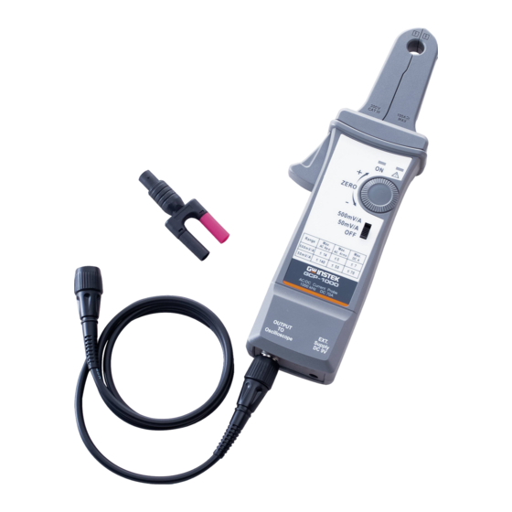
The GCP-1000 current probe enables a general purpose oscilloscope to display AC and DC current signals up to 70 amps Peak (50A RMS). The GCP-1000 current probe can also make AC and DC measurements with a multimeter by using the BNC-to-banana plug adapter. - Page 7 Table 1: GCP-1000 controls and indicators Control/Indicator Description Current flow symbol. The arrow shows the probe’s polarity convention for measuring current flowing from positive to negative. Zero adjustment. Rotate to adjust the probe output to zero when there is no current present. It may also be used to offset a DC signal component.
-
Page 8: Basic Operation
Do not clamp the probe onto circuits with voltages greater than 600 VAC. Personal injury or damage to the probe may result. Always connect the GCP-1000 current probe output to the instrument before clamping onto the circuit under test. 1. First connect the current probe BNC connector to double BNC connection cable then connect to oscilloscope input. - Page 9 See Figure 4. The sensitivity of the GCP-1000 current probe is multiplied times the number of loops in the jaws. For example: 500 mV/A X 4 turns = 2000 mV/A.
-
Page 10: Maintenance
GCP-1000 AC/DC Current Probe. 1. Notes on Battery and Power Converter: The GCP-1000 current probe uses a single square 9 V battery. This machine is a high power product. Please use the specified alkaline battery. As the battery in the GCP-1000 current probe is drained, significant gain errors may occur. - Page 11 GCP-1000 has in its design a priority external power circuit therefore it is safe to simultaneously install the battery and the external power supply. During usage, removing the external power supply will not produce waveform anomaly or any damage. However when external power is used for an extended time (more than 1 week), removal of battery is recommended.
- Page 12 Do not clean with solvents or abrasives. Do not immerse the probe. 4. Preparation for Shipment Our company has designed a special box to be used for GCP-1000, convenient for storage and shipment. Please do not discard it. If the original packaging is unfit for use or not available, use the following...
-
Page 13: Specifications
Specifications: These characteristics apply to an adjusted GCP-1000 AC/DC Current Probe installed on an oscilloscope of any brand. The oscilloscope must be warmed up for at least 20 minutes and be in an environment with the temperature at 10°C ~30°C and the humidity at 0~80%. - Page 14 Table 3: Voltage and current ratings Maximum working Maximum Maximum current (A) Working floating voltage (V) voltage (V) Range Range Rating 50 mV/A 500 mV/A DC + peak AC peak AC peak- 1200 peak RMS CAT III RMS CAT II RMS CAT I *See Figure 7 for frequency derating.
- Page 15 Table 5: Environmental Characteristics Temperature Working 0°C to +50°C (+32°F to +122°F) Storage -20°C to +80°C (-4°F to +176°F) Humidity 0°C to 40°C, 95% humidity 40°C to 50°C, 45% humidity Pollution Degree 500 mV/A range 50 mV/A range 5k 10k 50k 100k 500k 1M...
- Page 16 100k 500k 1M Figure 7. Maximum current versus frequency Figure 8. DC signal linearity in the 50 mV/A range, typical ...
- Page 17 50 mV/A range 500 mV/A range -100 Figure 9. Phase versus -150 frequency at 1 A peak, typical 100k 500k 1M Table 6: Certifications and compliances EC Declaration Compliance was demonstrated to the following of Conformity specification as listed in the Official Journal of the European Union: Low Voltage Directive 2014/35/EU -Low Voltage...
-
Page 18: Replaceable Parts
One BNC to banana plug adapter, designed with color fool proof design to avoid polarity mistake when connecting to digital meter. The GCP-1000 does not have any user repairable assemblies. If you should have trouble with your probe, contact your local Service Center or representative for help.
Need help?
Do you have a question about the GCP-1000 and is the answer not in the manual?
Questions and answers