Table of Contents
Advertisement
Quick Links
293 Wright Street • Delavan, WI 53115
Convertible
Jet Pumps
INSTALLATION, OPERATION, & PARTS MANUAL
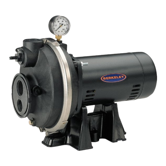
DESCRIPTION
Corrosion resistant convertible jet pumps (Models 3PL, 5PL,
7PL, 10PL, 10PLS11C and 15PLS11C) are adaptable to
either shallow or deep well installations. A shallow well ejec-
tor (purchase separately) is used for suction lifts of 25 feet
or less and can be used with drilled (cased) wells, driven
well points, and cisterns or lakes. With a deep well ejector
installed, the convertible jet pump can be used on wells up
to 110' deep (depending on ejector package used). Pump is
equipped with a capacitor start motor and a 30-50 psi preset
pressure switch.
UNPACKING
Open carton and remove pump. Check for loose, missing, or
damaged parts.
GENERAL SAFETY INFORMATION
READ AND FOLLOW
SAFETY INSTRUCTIONS!
This is the safety alert symbol. When you see this
symbol on your pump or in this manual, look for one of the
following signal words and be alert to the potential for
personal injury!
warns about hazards that will cause serious
personal injury, death or major property damage if ignored.
warns about hazards that can cause serious
personal injury, death or major property damage if ignored.
warns about hazards that will or can cause
minor personal injury or property damage if ignored.
NOTE: Indicates special instructions which are important but
not related to hazards.
Carefully read and follow all safety instructions in this manu-
al and on pump.
Keep safety labels in good condition.
Replace missing or damaged safety labels.
Electrical Safety
Hazardous voltage. Can shock, burn, or
cause death. Ground pump before connecting to power
supply. Disconnect power before working on pump, motor,
or tank.
© 2002
Models 3PL, 5PL, 7PL, 10PL,
10PLS11C, 15PLS11C
Capacitor voltage may be hazardous. To
discharge motor capacitor, hold insulated handle screwdriver
BY THE HANDLE and short capacitor terminals together. Do
not touch metal screwdriver blade or capacitor terminals. If
in doubt, consult a qualified electrician.
Wire motor for correct voltage. See "Electrical" section
of this manual, motor nameplate, and diagram inside motor
junction box cover.
Ground motor before connecting to power supply.
Meet United States National Electrical Code, Canadian
Electrical Code, and local codes for all wiring.
Follow wiring instructions in this manual and in motor
junction box when connecting motor to power lines.
General Safety
Hazardous pressure! Do not run pump
against closed discharge. Release all pressure on system
before working on any component.
Do not touch an operating motor. Modern
motors are designed to operate at high temperatures. To
avoid burns when servicing pump, allow it to cool for 20
minutes after shut-down before handling.
Do not allow pump or any system component to freeze. To
do so will void warranty.
Pump water only with this pump.
Periodically inspect pump and system components.
Wear safety glasses at all times when working on pumps.
Keep work area clean, uncluttered and properly lighted;
properly store all unused tools and equipment.
Keep visitors at a safe distance from the work areas.
Pump body may explode if used as a
booster pump unless relief valve capable of passing full
pump flow at 75 psi is installed.
Printed in U.S.A.
BE367 (Rev. 7/25/02)
Advertisement
Table of Contents

Related Manuals for Berkeley 3PL


Summary of Contents for Berkeley 3PL
- Page 1 INSTALLATION, OPERATION, & PARTS MANUAL DESCRIPTION Capacitor voltage may be hazardous. To Corrosion resistant convertible jet pumps (Models 3PL, 5PL, discharge motor capacitor, hold insulated handle screwdriver 7PL, 10PL, 10PLS11C and 15PLS11C) are adaptable to BY THE HANDLE and short capacitor terminals together. Do either shallow or deep well installations.
- Page 2 PERFORMANCE TABLE I – 4” Double Pipe Deep Well Performance and Ejector Chart - Ejector Package BK4800 Model 3PL Model 5PL Pressure in PSI Pressure in PSI Feet to Water GPM with J32P-24 Venturi and #54 Nozzle GPM with J32P-24 Venturi and #51 Nozzle –...
- Page 3 PERFORMANCE TABLE IV – 4” Double Pipe Deep Well Performance and Ejector Chart - Ejector Package BK4800 Model 7PL, 10PLS11C Model 10PL, 15PLS11C Pressure in PSI Pressure in PSI Feet to Water GPM with J32P-24 Venturi and #51 Nozzle GPM with J32P-28 Venturi and #55 Nozzle 11.0 10.0 24.5...
-
Page 4: Specifications
Width ........10-3/4” Length (3PL) ....... . 17”... - Page 5 Figure 5 – Cased Well Installation Figure 4 – Driven Point Installation 1. Install Berkeley ejector kit BK4875 (kits are sold sepa- 1. Install Berkeley ejector kit BK4875 (kits are sold sepa- rately). Follow the instructions provided with the kit. Align rately).
- Page 6 4. Lower the pipe into the water until the strainer is five feet above the bottom. It should also be at least 10 feet 1. Install Berkeley ejector kit BK4875 (sold separately). below the water level while the pump is running in order Follow the instructions provided with the kit.
-
Page 7: Discharge Pipe And Pressure Tank Connections
1. Mount the pump as close to the well as possible. the tank. Your new pump has a 30/50 psi switch, so 2. Assemble Berkeley ejector kit BK4840 (sold separately), adjust the tank pre-charge pressure to 28 psi. well piping, and well head adapter according to the instructions provided with the ejector package (See Figure 9.) Use galvanized drop pipe with turned cou-... -
Page 8: Electrical Installation
ELECTRICAL INSTALLATION 230 Volt to 115 Volt Conversion. Move plug to change voltage. Motor wires connect here. Ground Power supply wires connect here. Screw 230 Volt: Connect 2 hot wires (black and red) here and cap the white (neutral) wire. It does 230 V 115 V not matter which wire goes to which screw. -
Page 9: Operation
WIRING CHART – RECOMMENDED WIRE AND FUSE SIZES Max. Load Branch Fuse Distance in Feet from Motor to Supply Model Volts Amps Rating Amps* 0 - 100 101 - 200 201 - 300 301 - 400 401 - 500 115/230 8.8/4.4 15/15 14/14... -
Page 10: Preparing To Start The Pump - Shallow Well
6. After the pump has built up pressure in the system and 2. Replace all fill plugs. Leave the control valve open (in a shut off, check the pressure switch operation by opening shallow well installation, the control valve always stays a faucet or two and running enough water out to bleed open). -
Page 11: Troubleshooting Chart
TROUBLESHOOTING CHART Symptoms Things to Do: A. Motor will not run. A. Check that the disconnect switch is ON and that the circuit breaker has not tripped or the fuse has not blown. DISCONNECT POWER and make sure that wires connecting motor to power supply and pressure switch are tight and correctly connected (see Page 7). -
Page 12: Replacement Parts List
MODELS 3PL, 5PL, 7PL, 10PL, 10PLS11C, 15PLS11C 1171 0794 REPLACEMENT PARTS LIST Description Qty. 10PL 10PLS11C 15PLS11C Motor A100BHL A100CHL A100DHL A100EHL A100ELL A100FLL Water slinger 17351-0009 17351-0009 17351-0009 17351-0009 17351-0009 17351-0009 Pressure gauge U239-3 U239-3 U239-3 U239-3 U239-3 U239-3 1/2 x 1/8”... - Page 13 If within twelve (12) months from the date of installation or twenty-four (24) months from the date of manu- facture any such product shall prove to be defective, it shall be repaired or replaced at Berkeley’s/Wicor’s option, subject to the terms and conditions set forth below.
Need help?
Do you have a question about the 3PL and is the answer not in the manual?
Questions and answers