Table of Contents
Advertisement
Quick Links
293 Wright Street, Delavan, WI 53115
Phone: 888-237-5353
Fax: 800-321-8793
Web Site: berkeleypumps.com
© 2012
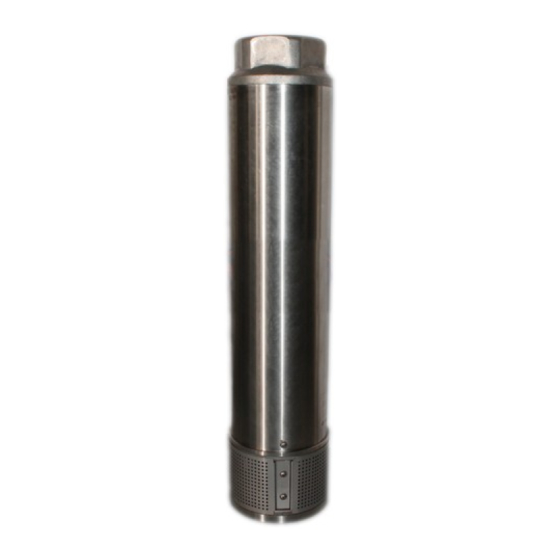
6TSP Series
Radial Flow
Installation/Operation/Parts
For further operating, installation, or maintenance assistance:
Call 1-888-237-5353
OWNER'S MANUAL
Submersible Turbine Pumps
BE959 (05/10/12)
Advertisement
Table of Contents

Related Manuals for Berkeley 6TSP Series


Summary of Contents for Berkeley 6TSP Series
- Page 1 OWNER’S MANUAL Submersible Turbine Pumps 293 Wright Street, Delavan, WI 53115 Phone: 888-237-5353 Fax: 800-321-8793 Web Site: berkeleypumps.com 6TSP Series Radial Flow Installation/Operation/Parts For further operating, installation, or maintenance assistance: Call 1-888-237-5353 © 2012 BE959 (05/10/12)
-
Page 2: Important Safety Instructions
Safety Important Safety Instructions System controls and pump must match. Do not interchange controls with other models. Serious damage SAVE THESE INSTRUCTIONS - This manual contains can result to the unit if pump and controls do not match. important instructions that should be followed during Average number of starts per day will influence motor installation, operation, and maintenance of the product. -
Page 3: Specifications • Warranty
Limited Warranty BERKELEY warrants to the original consumer purchaser (“Purchaser” or “You”) of the products listed below, that they will be free from defects in material and workmanship for the Warranty Period shown below. -
Page 4: Installation
Installation Pr einstallation Procedures And Taped splice - For wire sizes AWG 8 (8.4mm²) and larger: Checks 1. Cut off motor leads. Stagger lead and wire length so Grounding that 2nd lead is 2” (50mm) longer than 1st lead and Risk of electric shock. Can shock, burn or 3rd lead is 2”... -
Page 5: Installation / Electrical
Installation / Electrical 7. Wrap each joint tightly with electrical tape - cover wire for about 1-1/2” (4cm) on each side of joint. Make four passes with the tape - when finished you should have four layers of tape tightly wrapped around the wire. - Page 6 Installation Installation 1. Submerge cable and splice in steel barrel filled with water. Make sure both ends of cable are out of water. General 2. Clip one ohmmeter lead to barrel. Test each lead After completing all connections and tests so far, connect in cable successively by connecting the other a 5-foot length of pipe to pump.
-
Page 7: Electrical Tests
Installation Electrical Tests Check Valve at surface Risk of electric shock. Can shock, burn or To Service kill. Only qualified electricians should perform these tests. When testing, use all normal precautions for the voltages involved. 200' Max Electrical Test Of Motor, Cable, Connections Top Check The cable and splices can be damaged as the pump is To Surface... -
Page 8: Installation • Test
Installation • Test Load Current Test Controller Load current should be obtained on each motor lead at Incoming the controller. Partially close pump discharge valve (keep Power pressure and flow within specified operating range) until maximum amp reading has been obtained (Figure 13). Ground Compare reading with motor nameplate rating. - Page 9 Test 3. If resistance reading goes to zero after touching any A. For each hookup, add the readings for the three legs: of the wires, the pump should be raised to determine Ex.: Hookup #1 Hookup #2: Hookup #3 location of ground fault (cable, motor, or splice). L1 = 51Amps L1 = 50 Amps L1 = 50 Amps...
-
Page 10: Checking Pump Performance
To assure quality are above ground, not in the pump itself. and integrity of the unit, have your pump serviced by authorized Berkeley personnel. Preventive Maintenance To avoid major repairs, make the checks listed below every 4 to 6 months. -
Page 11: Troubleshooting
Check pump shut-off pressure. Pressure should be at least 90% of pressure at installation. Pump parts worn from abrasives. b) Call Berkeley Pumps. Intake screen clogged. Remove pump from well and clean screen. a) Reduce pressure switch setting until pump will shut off. - Page 12 Notes...
Need help?
Do you have a question about the 6TSP Series and is the answer not in the manual?
Questions and answers