Table of Contents
Advertisement
Quick Links
Advertisement
Table of Contents

Related Manuals for Crystal Vision AADA416FR


Summary of Contents for Crystal Vision AADA416FR
- Page 1 AADA416FR Analogue Audio Distribution Amplifier Crystal Vision Ltd., Lion Technology Park, Station Road East, Whittlesford, Cambridge, CB22 4WL, England. Tel: +44(0) 1223 497049 Fax: +44(0) 1223 497059 sales@crystalvision.tv www.crystalvision.tv...
-
Page 2: Table Of Contents
Overvoltage detection level Silence detection level Using the active front panel Selecting the AADA416FR Navigating the display Using the shaft encoder The AADA416FR active panel menu structure Shorthand codes Adjusting channel gain Channel status Adjusting alarm settings Configuring GPI outputs AADA416FR User Manual R1.9... - Page 3 Amendment to Specification table, page 33-34 08/08/08 Revision 7 RM37 phasing amended (page 10) 25/11/09 Revision 8 RM37 Audio out table amended (page 8) 02/03/10 Revision 9 RM17 connection table amended (page 6) 23/01/14 AADA416FR User Manual R1.9 22 May 2018...
-
Page 4: Introduction
Statesman. AADA416FR quad distribution amplifier The AADA416FR can be configured in any of the following modes: • 4 channels - each channel is 1-in 4-out • 3 channels - channels 1 and 2 are 1-in 4-out; channel 3 is 1-in 8-out •... -
Page 5: Revision 4 Rm37 Connection Tables Updated, Pages
• Card edge, active/remote panel and Statesman control options The AADA416FR is a 100mm x 266mm module, which fits in the three standard frames and can be integrated with any boards from the company’s full product range. It uses the RM17 and RM37 single height rear connectors. -
Page 6: Hardware Installation
2.1 Rear modules and signal I/O The AADA416FR is used with the RM17 and the RM37 “easywire” single slot rear connectors in all Crystal Vision frames. -
Page 7: Revision 6 Amendment To Specification Table
OP3C+ Audio 3 OP3B+ Audio 3 OP3D+ Audio 3 OP4C- Audio 4 OP4A+ Audio 4 OP4D- Audio 4 OP4A- Audio 4 OP4C+ Audio 4 OP4B- Audio 4 OP4B+ Audio 4 OP4D+ Audio 4 AADA416FR User Manual R1.9 22 May 2018... - Page 8 Stereo 2 channel uses Audio 3 for left signal (L2) and Audio 4 for right signal (R2). In 2-in, 2x8-out mode, it is worth noting that headphone monitor 1 has audio 1 on both channels, and headphone monitor 2 has audio 3 on both channels. AADA416FR User Manual R1.9 22 May 2018...
-
Page 9: Using Unbalanced Audio
Pin numbers refer to the plug numbering scheme. 2.2 Using unbalanced audio As the AADA416FR outputs are floating, it is possible to obtain up to 16 unbalanced audio outputs by wiring the RM17 or RM37 in the correct manner. An unbalanced output may be obtained by using either the +ve or –ve phase of the audio signal pair. -
Page 10: General Purpose Interface
Hardware installation 2.3 General purpose interface GPI outputs ‘a’ to ‘d’ use switch-closure to indicate AADA416FR status. When closed- circuit, the GPI line is connected to frame ground. As supplied, each GPI output has a 330Ohm resistor in series with its output. This allows for an external LED connected to a DC supply voltage of +5V. - Page 11 2 and +5V @500mA is pin 1 in each case. Remote 2 and remote 4 are 26-way high density D-Type male plugs and frame ground is pin 6 and +5V @500mA is pin 15 in each case. AADA416FR User Manual R1.9 22 May 2018...
- Page 12 Remote 1: 26-way high density D-Type socket. Frame ground is pin 2 and +5V @500mA is pin 1. Remote 2: 26-way high density D-Type plug. Frame ground is pin 6 and +5V @500mA is pin 15. AADA416FR User Manual R1.9 22 May 2018...
-
Page 13: Configuration
Other Crystal Vision rear modules and interface cards can be mixed in any quantity with AADA416FR cards, up to a maximum of 12 cards, providing the other cards do not exceed the power rating of the PSU chosen (normally 150W). -
Page 14: Monitoring Output
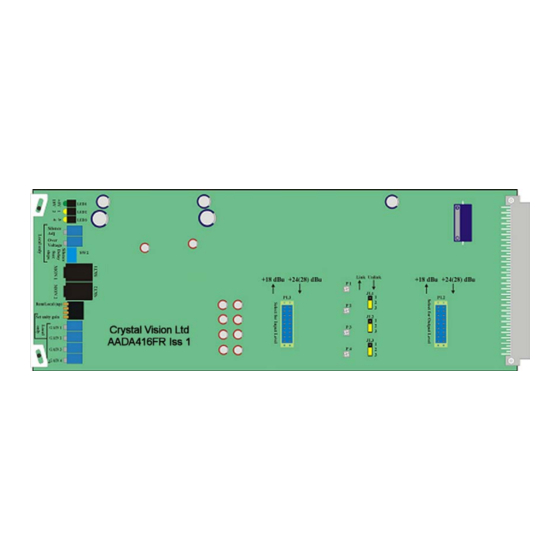
3.5mm jack is audio 4 and the ring is audio 3. Linking audio channels together Links JL1, JL2 and JL3 on the AADA416FR board allow audio channels 1 to 4 to be configured in any of the following modes. - Page 15 Crystal Vision Hardware installation AADA416FR showing channel combining links Modes Comments 4 separate audio channels Unlink Unlink Unlink Audio 4 outputs same as audio 3 outputs and uses audio 3 input Unlink Unlink Link Audio 4 gain pot is out of circuit...
-
Page 16: Changing The Maximum Operating Level
4 channels by 6dB and decrease the output gain of all 4 channels by 6dB Note: In the upper position, the lowest two pins of the 20 way plugs on the main module should go through the lower holes in the PCB header block. AADA416FR User Manual R1.9 22 May 2018... - Page 17 -/+6 dB. Statesman and the active panel LCD display will take into account the position of PL3 and PL2 when showing the available gain range. AADA416FR User Manual R1.9 22 May 2018...
-
Page 18: Card Edge Operation
Card edge operation 3 Card edge operation Once the start-up initialisation procedure is complete, the AADA416FR card can be controlled or configured from the card edge, the active control panel or the Statesman PC Control System. This chapter will concentrate on the card edge controls. -
Page 19: Audio Gain
‘Audio Gain’. The AADA416FR is supplied with a factory-set gain of 0dB. Easy unity gain setup The AADA416FR allows a special mode for adjusting the four controls, for gain of 0dB, without the use of external audio signals and level meters. •... - Page 20 In remote mode, many of the above adjustments can be set to different values to that set Note: in local mode. These values are retained through power down, and restored when the unit is powered up. AADA416FR User Manual R1.9 22 May 2018...
-
Page 21: Using The Active Front Panel
Note: passwords cleared prior to using the panel for the first time. At power up, the 2-line 20-character screen will display ‘Crystal Vision’ followed by the firmware version number for the control panel. All 8 control panel key LEDs will illuminate. -
Page 22: Selecting The Aada416Fr
The AADA416FR Home menu Note: The AADA416FR will need to have the card edge local/remote switch (lever 1) in the DOWN position to enable active or remote control panel operation. Refer to the Card edge operation chapter or Installation chapter for more information. -
Page 23: Using The Shaft Encoder
• Rotary control – shaft encoder used to select options or variable data Note: Please refer to the Crystal Vision Control Panel manual for details of the Panel Setup, Lock Panel and Diagnostic menus. Using the shaft encoder The shaft encoder function is dependent on the menu currently active. In general in top- level menus the shaft encoder is used to cycle through settings or functions to adjust. -
Page 24: Shorthand Codes
• SIL – audio level is below silence limit for a given time limit • OK – audio level is above silence limit and below overvoltage limit • OV – audio level is above overvoltage limit AADA416FR User Manual R1.9 22 May 2018... -
Page 25: Adjusting Alarm Settings
The silence threshold and overvoltage level values in remote mode and local mode may be different to each other and are retained through power down, and restored when the unit is powered up. AADA416FR User Manual R1.9 22 May 2018... -
Page 26: Configuring Gpi Outputs
GPI inputs 'e' and 'f' as explained in the Installation chapter. The selection in remote mode and local mode may be different to each other and are retained through power down, and restored when the unit is powered up. AADA416FR User Manual R1.9 22 May 2018... -
Page 27: Statesman
Note: For further details of Statesman configuration and operation please refer to the Statesman manual. AADA416FR User Manual R1.9 22 May 2018... -
Page 28: Controlling Audio Channel Gain
Controls’ in the Tools menu. The control is only available when a module application is active and controls have been ganged. To set a channel to its default value of zero gain click on the CAL button at the bottom of the slider. AADA416FR User Manual R1.9 22 May 2018... -
Page 29: Setting Error And Gpi Options
Although the minimum indication for the silence detect delay shows zero, it is around 2 Note: seconds in practice. Enabling GPI warnings GPI warnings may be enabled for the following errors and error combinations • Silence or over voltage • Silence • Over voltage AADA416FR User Manual R1.9 22 May 2018... - Page 30 Default values To set a parameter to its default value click on the CAL button at the bottom of the slider. Default values from left to right are 56 seconds, -30dBu and 25dBu. AADA416FR User Manual R1.9 22 May 2018...
-
Page 31: Trouble Shooting
The front edge of the card provides useful power rail monitoring, in addition to card edge controls and headphone monitoring outputs. AADA416FR front edge view The bottom green LED indicates good +/- 18 Volt power rails when lit and the upper green LED indicates a good +5 Volt rail when lit. - Page 32 If required, the card may be reset by simply removing the rack power and re-applying power after a few seconds or by removing the card from the rack and then re-inserting the card It is safe to re-insert the card whilst the rack is powered AADA416FR User Manual R1.9 22 May 2018...
-
Page 33: Specification
>104dB , 0dB gain, 0dBFS = +24dBu (20Hz to 20kHz) Frequency response: ± 0.05dB 20Hz to 20kHz. Total Harmonic Distortion <0.003% at 1kHz, +18dBu/+24dBu (THD): Common Mode Rejection: > 74 dB (20Hz to 20kHz) Channel to Channel cross < -100dB, 10kHz talk: AADA416FR User Manual R1.9 22 May 2018... - Page 34 4, active low, 330 Ohm resistors in series with output to drive LEDs. Indicates silence/overvoltage status per channel Status monitoring LED display Front of card edge visual monitoring with LED indicators to indicate: PSU rails present Overvoltage/silence per channel AADA416FR User Manual R1.9 22 May 2018...
Need help?
Do you have a question about the AADA416FR and is the answer not in the manual?
Questions and answers