Table of Contents
Advertisement
Quick Links
Advertisement
Table of Contents

Summary of Contents for Crystal Vision AADA-VF
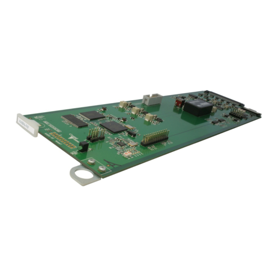
- Page 1 AADA-VF Analogue audio distribution amplifier Crystal Vision Ltd., Lion Technology Park, Station Road East, Whittlesford, Cambridge, CB22 4WL, England. Tel: +44(0) 1223 497049 Fax: +44(0) 1223 497059 sales@crystalvision.tv www.crystalvision.tv...
-
Page 2: Table Of Contents
Hardware installation Board configuration Link configuration Inserting cards Rear modules and signal I/O Status monitoring Controlling cards via VisionWeb Menu Structure Control Descriptions Status Control Troubleshooting Card edge monitoring Basic fault finding guide Specification AADA-VF User Manual R1.0 18 November 2016... -
Page 3: Introduction
(stereo), one input to four outputs twice or as single channel (mono), one input to eight outputs. Both channels have individual gain adjustment of ±30dB. The AADA-VF is a space-saving 96mm x 325mm module which fits in the standard Vision frames from Crystal Vision. - Page 4 Crystal Vision Introduction Silence and overvoltage detection Remote monitoring and control via VisionPanel, VisionWeb control system, SNMP and the frame active panel AADA-VF User Manual R1.0 18 November 2016...
-
Page 5: Hardware Installation
2 Hardware installation 2.1 Board configuration AADA-VF card Link configuration The AADA-VF has no user-selectable links. Any links or controls should remain in their factory set positions. Inserting cards Cards can be plugged in and out of powered Vision frames without damage. -
Page 6: Rear Modules And Signal I/O
Rear modules and signal I/O 3 Rear modules and signal I/O The AADA-VF audio distribution amplifier fits into all Vision rack frames from Crystal Vision and can be plugged in and removed while the frame is powered without damage. Vision frames all have a hinged front panel that gives access to the PSUs and all cards. The universal frame wiring system allows any of the interface range of cards to be fitted in any position with the use of removable rear modules. -
Page 7: Status Monitoring
Typical Vision 3 frame homepage The example above shows an AADA-VF card fitted in slots 1 and 7. Other Vision cards are in slots 2, 3, and 5. Clicking on either AADA-VF card will bring up the card’s Status page, for... -
Page 8: Menu Structure
Crystal Vision Status monitoring 4.2 Menu Structure Operators of a Vision frame active front panel or VisionPanel should use the following tree to access the AADA-VF status: Status Channel 1 Silent Over Voltage Channel 2 Silent Over Voltage Control Audio Gain... - Page 9 Set the threshold from -42 to -30dBu that the input audio must be (dBu level) consistently below to be considered ‘silent’. Over voltage Set the input level threshold from +12 to +24dBu that, above (dBu level) which, the ‘over voltage’ status indicator will be illuminated. AADA-VF User Manual R1.0 18 November 2016...
- Page 10 1 to all eight outputs. Setting the lower option routes Input 1 to four of the outputs and Input 2 to the other four. Set the AADA-VF to its default settings: Gain 0dB, Silence level Card defaults -30dBu, Overvoltage level +24dBu.
-
Page 11: Troubleshooting
If required, the card may be reset by removing the card from the frame and then re-inserting it. It is safe to re-insert the card whilst the frame is powered. Any previous configuration will be retained. AADA-VF User Manual R1.0 18 November 2016... -
Page 12: Specification
Complimentary SNMP control and monitoring via frame CPU and Ethernet connection. Silence warning: Silence threshold -42 dBu to -30dBu. Delay time 2-120 secs. Over-voltage indication: User set to between +12 to +24dBu. AADA-VF User Manual R1.0 18 November 2016...


Need help?
Do you have a question about the AADA-VF and is the answer not in the manual?
Questions and answers