Table of Contents
Advertisement
Quick Links
Advertisement
Table of Contents

Related Manuals for Crystal Vision VDA210R


Summary of Contents for Crystal Vision VDA210R
- Page 1 VDA210R Analogue video distribution amplifier Crystal Vision Ltd., Lion Technology Park, Station Road East, Whittlesford, Cambridge, CB22 4WL, England. E-mail: sales@crystalvision.tv Website: www.crystalvision.tv Tel: +44(0) 1223 497049 Fax: +44(0) 1223 497059...
-
Page 2: Table Of Contents
Cal all 4 Using the active control panel Selecting the VDA210R Navigating the display 4.1 The VDA210R active panel menu structure Shorthand codes 4.2 Adjusting video gain and EQ 4.3 Input video status and settings 4.4 Checking the output and adjusting clamp/alarm settings 4.5 Recalling factory defaults... - Page 3 Crystal Vision VDA210R User Manual V3.21 5 Card edge operation 6 Hardware installation 6.1 Universal rear connectors Rear module connections with RM01 Rear module connections with RM15 Rear module connections with RM18 Rear module connections with RM02 6.2 General purpose interface 6.3 Configuration...
-
Page 4: Introduction
Crystal Vision Introduction 1 Introduction The VDA210R is a dual analogue video distribution amplifier with two inputs. In dual channel mode it supports up to five main outputs per channel. In single channel mode, it supports up to ten main outputs. - Page 5 Luma/Chroma operation • Bulb or LED GPI drive capability • Card edge, active/remote panel and Statesman control options This manual covers the dual channel VDA210R. The single channel VDA110R and the Note: VDA110M/210M without remote control are also available. 22/09/05...
-
Page 6: Installing Statesman
Running Statesman for the first time The Statesman PC Control System may be run from the Crystal Vision programs folder via the Start menu or by double clicking on the Crystal Vision.exe file in the installed program directory. When the program runs it will require licence information and an administrator name and password. -
Page 7: Statesman Operation
Crystal Vision VDA210R User Manual V3.21 3 Statesman operation Once Statesman is configured it should automatically detect any statesman compatible modules in the connected frame or frames and display them in the left hand explorer-style window of the main application. -
Page 8: Video Status And Settings
Luma Over Yellow Output Luma levels >110% of peak white Luma Dark Yellow Output Luma level <15% of peak white for time delay set by rotary Delay control Green 525-line signal input Green 625-line signal input 22/09/05 VDA210R User Manual V3.21... -
Page 9: Input Standard Select
PAL-N or PAL-N (Argentina). NTSC-M PAL-M or NTSC-M (Japan). Source select The VDA210R can be operated in two modes: • 2 x 5 – dual channel mode; seconds channel uses Input 2 as source • 1 x 10 – single channel mode; second channel uses Input 1 as source To change mode check either Input 1 or Input 2 as the source for Channel 2. -
Page 10: Setting Alarm/Clamp Options And Recalling Factory Defaults
60 lines. Off selects an AC-coupled output. Cal all Click on Cal All to clear all user adjustments and set the VDA210R to factory defaults. Note: For further details of Statesman configuration and operation please refer to the Statesman manual. -
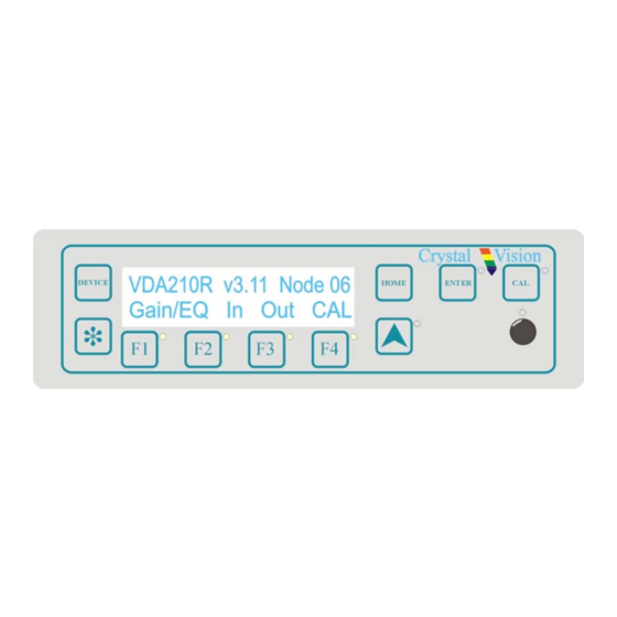
Page 11: Using The Active Control Panel
Note: passwords cleared prior to using the panel for the first time. At power up, the two line 20-character screen will display ‘Crystal Vision’ followed by the firmware version number for the control panel. All eight-control panel keys LEDs will illuminate. -
Page 12: Selecting The Vda210R
'Remote Ctrl Disabled' will be displayed. The VDA210R home menu The VDA210R will need to have the card edge local/remote switch (lever 2) in the Note: DOWN position to enable active or remote control panel operation. Refer to the Card edge operation chapter or Installation chapter for more information. -
Page 13: Navigating The Display
Upward arrow – used to move up the menu structure / enter lock panel menu from the Device menu • Rotary control – shaft encoder used to select options or variable data Please refer to the Crystal Vision Control Panel manual for details of the Panel Setup, Note: Lock Panel and Diagnostic menus. 22/09/05... -
Page 14: The Vda210R Active Panel Menu Structure
Using the active control panel 4.1 The VDA210R active panel menu structure The main top-level menus for the VDA210R module are obtained by pressing the F1, F2, F3 and F4 keys from that module’s HOME menu. Menu keys are illuminated when active and when further menus are available. -
Page 15: Adjusting Video Gain And Eq
Crystal Vision VDA210R User Manual V3.21 4.2 Adjusting video gain and EQ Pressing F1 from the home menu will display the gain/EQ menu. Description Channel gain menu Press the F1 for the Ch 1 gain menu Press the F2 for the Ch 1 equalisation menu... -
Page 16: Input Video Status And Settings
2 to DC-restore output 2. If F1 is pressed for CBRUV (chroma) channel 2 error detection is disabled and the output clamp uses the sync pulses on input 1 to DC- restore output 2. 22/09/05 VDA210R User Manual V3.21... -
Page 17: Checking The Output And Adjusting Clamp/Alarm Settings
Crystal Vision VDA210R User Manual V3.21 4.4 Checking the output and adjusting clamp/alarm settings Pressing F3 from the home menu will display the Output menu. The following settings can be adjusted: • Check – output luminance status • Clamp – display/set DC restoration setting •... -
Page 18: Recalling Factory Defaults
Pressing the F4 key provides access to factory defaults recall (CAL) menu. Description Cal menu Press F4 from the home menu to display the CAL menu Press the CAL key to clear all user adjustments & set the VDA210R to factory defaults. 22/09/05 VDA210R User Manual V3.21... -
Page 19: Card Edge Operation
VDA210R User Manual V3.21 5 Card edge operation Once the start-up initialisation procedure is complete, the VDA210R card can be controlled or configured from the card edge, the active control panel or the Statesman PC interface. This chapter will concentrate on the card edge controls. - Page 20 Changing the output setup – match video content error processing to video format • Changing channel two format type – optimise error correction and clamp for signal type • Changing output 2 input source – single (1 x 10) or dual (2 x 5) channel operation 22/09/05 VDA210R User Manual V3.21...
-
Page 21: Hardware Installation
I/O access and module packing density. The VDA210R may be used with the RM01 single slot rear connector for up to 12 modules, the RM02 quadruple slot rear connector for up to 4 modules and the RM15 and RM18 double slot rear connectors for up to 6 modules in a 2U frame. -
Page 22: Rear Module Connections With Rm01
Not used Input 2 Loop-Through Channel B Loop Output 1 Output 2 Channel B 1 Channel B 2 Output 1 Output 2 Channel B 3 Output 1 Output 2 Channel B 4 Output 1 Output 2 22/09/05 VDA210R User Manual V3.21... -
Page 23: Rear Module Connections With Rm18
Crystal Vision VDA210R User Manual V3.21 Rear module connections with RM18 RM18 fits in all frames Description RM18 • 6 modules per 2U frame, 3 per 1U frame, 1 per DTB • 1 module per rear connector • 6 connections available •... -
Page 24: Rear Module Connections With Rm02
Card 3 fits in slots 4, 8 and 12 • No card fits in 3, 7 or 11 Single-channel configuration Dual-channel configuration A input Input Input 1 B input Not used Input 2 A out Output Output 1 B out Output Output 2 22/09/05 VDA210R User Manual V3.21... -
Page 25: General Purpose Interface
Crystal Vision VDA210R User Manual V3.21 6.2 General purpose interface GPI outputs use switch-closure to indicate VDA210R status. When closed circuit, the GPI line is connected to Frame Ground. Closed-circuit (Ground) Open-circuit ‘a’ Input 1 absent Input 1 present ‘b’... - Page 26 GPI lines ‘a’ to ‘f’ of each card connect to the rear remote connector as follows: Slot no. ‘a’ pin ‘b’ pin ‘c’ pin ‘d’ pin ‘e’ pin ‘f’ pin Remote connector is 15 way normal density D-type socket. Frame ground is pin 15. Note: 22/09/05 VDA210R User Manual V3.21...
-
Page 27: Configuration
VDA210R User Manual V3.21 6.3 Configuration The VDA210R is equipped with 5 on-board jumper links. These are PL2 (75R/HiZ) and PL4 to PL7 (local configuration) as shown below: Other settings or adjustments on the card should normally be left in the factory default positions. -
Page 28: Changing Channel Two Format Type (Local Mode Only)
R148, R150, R173, R175 and R177 (labelled 'A' to 'F') must be changed from 0Ω to 680Ω 0805 surface-mount types. The module can be supplied with LED drive resistors if requested at the time of ordering. Note: Other adjustments on the card should normally be left in the factory default positions. 22/09/05 VDA210R User Manual V3.21... -
Page 29: Problem Solving
Crystal Vision VDA210R User Manual V3.21 7 Problem solving The front edge of the card provides useful power rail and video monitoring in addition to card-edge controls and status LEDs. VDA210R front edge view The left hand group of LEDs are for channel one and the right hand group are for channel two. - Page 30 If required, the card may be reset by simply removing the rack power and re-applying power after a few seconds or by removing the card from the rack and then re-inserting the card It is safe to re-insert the card whilst the rack is powered 22/09/05 VDA210R User Manual V3.21...
-
Page 31: Specification
Crystal Vision VDA210R User Manual V3.21 8 Specification General Dimensions 100mm x 266 mm module with DIN 41612 connector Weight 170g Power consumption Inputs Video 2 analogue. Input loop-through available with selected rear modules Outputs Number and type: 10 (maximum) cable-equalised analogue... - Page 32 Quad slot rear module with 27 BNCs for 3 boards RM15 Dual slot rear module for 1 dual VDA with 12 BNCs. Allows loop- throughs RM18 Dual slot rear module for 1 VDA with 12 BNCs. 22/09/05 VDA210R User Manual V3.21...
Need help?
Do you have a question about the VDA210R and is the answer not in the manual?
Questions and answers