Table of Contents
Advertisement
Quick Links
Advertisement
Table of Contents

Summary of Contents for Crystal Vision VDA110M
- Page 1 VDA110M Analogue video distribution amplifier Crystal Vision Ltd., Lion Technology Park, Station Road East, Whittlesford, Cambridge, CB22 4WL, England. E-mail: sales@crystalvision.tv Website: www.crystalvision.tv Tel: +44(0) 1223 497049 Fax: +44(0) 1223 497059...
-
Page 2: Table Of Contents
Rear module connections with RM16 Rear module connections with RM02 Rear module connections with RM10 3.2 General purpose interface 3.3 Configuration Changing the input termination Changing the GPI output drive 4 Problem solving 5 Specification 22/09/05 VDA110M User Manual V1.1... -
Page 3: Introduction
The unit plugs into the front of the rack frame, and the universal connection system allows a mixture of Crystal Vision modules in the frame. The hinged front panel of the case reveals LED indication of input status and controls for cable equalisation and gain. -
Page 4: Card Edge Operation
Crystal Vision Card edge operation 2 Card edge operation The front edge of the VDA110M card provides power rail monitoring, signal status and gain/EQ adjustments for each input. There is no provision for remote control. VDA110M front edge view Location/colour Meaning when lit... -
Page 5: Hardware Installation
I/O access and module packing density. The VDA110M may be used with the RM01 and RM09 single slot rear connector for up to 12 modules, the RM02 and RM10 quadruple slot rear connectors for up to 4 modules and the RM16 and RM18 double slot rear connectors for up to 6 modules in a 2U frame. -
Page 6: Rear Module Connections With Rm01
12 modules in 2U, 6 in 1U & 2 in a DTB • All frame slots can be used Signal assignment Input. LOOP IN Input loop through OUT 1 Output OUT 2 Output OUT 3 Output OUT 4 Output 22/09/05 VDA110M User Manual V1.1... -
Page 7: Rear Module Connections With Rm18
1 module per rear connector • 6 connections available • Card fits in upper slot • No card fits in lower slot Signal Output Input Output Output Output Output Output Output Output Output Output Output 22/09/05 VDA110M User Manual V1.1... -
Page 8: Rear Module Connections With Rm16
1 module per rear connector • 6 connections available • Card fits in upper slot • No card fits in lower slot Signal Input Loop Video Loop Video Output Output Output Output Output Output Output Output Output Output 22/09/05 VDA110M User Manual V1.1... -
Page 9: Rear Module Connections With Rm02
Card 2 fits in slots 2, 6 and 10 • Card 3 fits in slots 4, 8 and 12 • No card fits in 3, 7 or 11 Signal A Input Input B Input Output A Output Output B Output Output 22/09/05 VDA110M User Manual V1.1... -
Page 10: Rear Module Connections With Rm10
Card 2 fits in slots 2, 6 and 10 • Card 3 fits in slots 4, 8 and 12 • No card fits in 3, 7 or 11 Signal Input LOOP Input loop through Output Output Output Output Output Output Output 22/09/05 VDA110M User Manual V1.1... -
Page 11: General Purpose Interface
Crystal Vision Hardware installation 3.2 General purpose interface GPI outputs use switch-closure to indicate VDA110M status. When closed circuit, the GPI line is connected to Frame Ground. Each GPI output can drive a 24V bulb (max current 500mA). Closed-circuit (Ground) Open-circuit ‘a’... - Page 12 GPI lines ‘a’ to ‘f’ of each card connect to the rear remote connector as follows: Slot no. ‘a’ pin ‘b’ pin ‘c’ pin ‘d’ pin ‘e’ pin ‘f’ pin Note: Remote connector is 15 way normal density D-type socket. Frame ground is pin 15. 22/09/05 VDA110M User Manual V1.1...
-
Page 13: Configuration
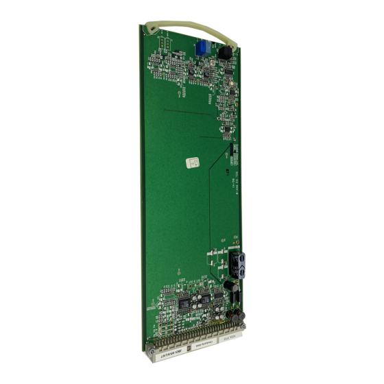
Crystal Vision Hardware installation 3.3 Configuration The VDA110M is equipped with an on-board jumper link to change input termination. VDA110M showing termination jumper and GPI drive resistor Changing the input termination Move jumper PL2 to the appropriate position to set the input termination to either 75Ω or high impedance loop through. -
Page 14: Problem Solving
The front edge of the card provides useful power rail and video monitoring in addition to card-edge controls and status LEDs. VDA110M front edge view The top red LED is not used. The lower left hand PSU green LED indicates good power rails when lit. - Page 15 If required, the card may be reset by simply removing the rack power and re-applying power after a few seconds or by removing the card from the rack and then re-inserting the card It is safe to re-insert the card whilst the rack is powered 22/09/05 VDA110M User Manual V1.1...
-
Page 16: Specification
Signal to noise ratio: < -60dB weighted GPI lines Outputs: 1 ( D-type on frame ) Input presence/absent Status monitoring LED display Front of card edge visual monitoring with LED indicators to indicate: PSU rails present Input present 22/09/05 VDA110M User Manual V1.1... - Page 17 Quad slot rear module with 27 BNCs for 3 boards. Allows loop- through for single VDAs RM16 Dual slot rear module for 1 VDA with 12 BNCs. Allows single loop-through RM18 Dual slot rear module for 1 VDA with 12 BNCs. Accesses all 11 outputs. 22/09/05 VDA110M User Manual V1.1...


Need help?
Do you have a question about the VDA110M and is the answer not in the manual?
Questions and answers