TFT EXTEND-A-GUN XG18 Manual
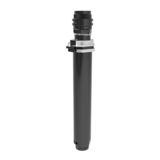
Telescoping waterway for deck mounted monitors
Hide thumbs
Also See for EXTEND-A-GUN XG18:
Table of Contents
Advertisement
Quick Links
INSTRUCTIONS FOR INSTALLATION, SAFE OPERATION AND MAINTENANCE
DANGER
To make the Extend-A-Gun as versatile as
possible three mounting bracket kits are offered.
Each kit has a different upper bracket, the lower
bracket is the same in all three.
XGB-13 TUBE/SADDLE
BRACKET SET
XGB-23 PLATE/SADDLE
BRACKET SET
XGB-33 SADDLE/SADDLE
BRACKET SET
TASK FORCE TIPS LLC
MADE IN USA • TFT.com
©Copyright Task Force Tips LLC 2002-2019
Telescoping Waterway for Deck Mounted Monitors
Read instruction manual before use. Operation of this device without understanding the manual
and receiving proper training is a misuse of this equipment. A person who has not read and
understood all operating and safety instructions, is not qualifi ed to operate the Extend-A-Gun
telescoping unit.
** - OUTLETS SHOWN ARE
FOR MODELS XG18PL - XL & XG18-VL-XL
FOR MODELS WITH 3" MAKE NPT OUTLET, ADD 1"
MANUAL: EXTEND-A-GUN
3" NPT
3701 Innovation Way, Valparaiso, IN 46383-9327 USA
800-348-2686 • 219-462-6161 • Fax 219-464-7155
MODEL XG18
SHOWN WITH TFT MASTER NOZZLE
AND CROSSFIRE DECK GUN
ALTERNATE:
1) MOUNTING PLATE, 9" SQ.
TFT PART XGB-23
2) SADDLE BRACKET
TFT PART XGB-33
LIX-518 January 23, 2019 Rev12
Advertisement
Table of Contents

Related Manuals for TFT EXTEND-A-GUN XG18


Summary of Contents for TFT EXTEND-A-GUN XG18
- Page 1 To make the Extend-A-Gun as versatile as possible three mounting bracket kits are offered. Each kit has a different upper bracket, the lower bracket is the same in all three. SHOWN WITH TFT MASTER NOZZLE AND CROSSFIRE DECK GUN XGB-13 TUBE/SADDLE BRACKET SET 3"...
-
Page 2: Table Of Contents
Table Of Contents 1.0 MEANING OF SIGNAL WORDS ..........3 2.0 SAFETY 3 3.0 BRACKET SETS ................ 4 3.1 MECHANICAL SPECIFICATIONS ........4 3.2 PART IDENTIFICATION MODELS ........5 3.3 PLATE BRACKET INSTALLATION ........5 4.0 SIDE LOADS AT MOUNTING POINTS ........6 5.0 INDICATOR SWITCH WIRING .......... -
Page 3: Meaning Of Signal Words
1.0 MEANING OF SAFETY SIGNAL WORDS A safety related message is identifi ed by a safety alert symbol and a signal word to indicate the level of risk involved with a particular hazard. Per ANSI standard Z535.4-2007, the defi nitions of the four signal words are as follows: DANGER indicates a hazardous situation which, if not avoided, will result in death or serious DANGER injury. -
Page 4: Bracket Sets
3.0 BRACKET SETS For safe dependable service, the Extend-A-Gun MUST be securely mounted. To make the Extend-A-Gun as versatile as possible, three mounting bracket kits are off ered. Each kit has a diff erent upper bracket. The lower bracket is the same in all three. Task Force Tips strongly recommends that Extend-A-Gun be installed using the bracket sets, WARNING sold by Task Force Tips, that are designed for this purpose. -
Page 5: Part Identification Models
3.2 PART IDENTIFICATION AND MODELS PART DESCRIPTION VT50-13NT 1/2-13 HEX NUT XG486 SADDLE BRACKET XG476 4-1/2 U-BOLT 1/2 DIA. 3.3 PLATE BRACKET INSTALLATION This kit may be used in either new or retro-fi t installations. The top plate with its bracket may be bolted above or below an existing deck. -
Page 6: Side Loads At Mounting Points
4.0 SIDE LOADS AT MOUNTING POINTS Before installing Extend-A-Gun MUST determine forces that will WARNING be exerted in the proposed installation by the reaction force of the nozzle. Determine distance, inches, from the center of the monitor elevation joint to the bottom of the threads in the monitor inlet. D1 FOR MOST COMMON INSTALLATIONS Task Force Tips CROSSFIRE D1 = 1"... -
Page 7: Indicator Switch Wiring
4) Determine the distance, D3 in inches, from the center of the upper mounting inches bracket to the center of the lower mounting bracket for the proposed installation. D3 MUST be between D3 min and D3 max. 5) Calculate forces on Brackets, Add D1 + D2 + D3 + 15.7 = + D2 + D3 + 21.7 = L... -
Page 8: Labels
Moving Vehicle. TASK FORCE TIPS, 3701 Innovation Way, Valparaiso, IN 46383-9327 +1 219 462-6161 • 800 348-2686 • www.tft.com • MADE IN U.S.A. X X GL010 Attach the rectangular instruction label (XGL010) to a smooth fl at surface where it can be read by the person operating the Extend- a-Gun and monitor. -
Page 9: Extend
8.1 EXTEND Make certain the valve to the deck gun is closed. Lift the slide bar on the Extend-A-Gun latch mechanism with one hand and lift the deck gun straight up with your other hand. The slide bar should be released after the deck gun has moved out of the retracted position. Notice the word “UNLOCKED” appear on the top surface of the pawls. -
Page 10: Exploded View & Parts List
9.0 EXPLODED VIEW AND PARTS LIST ©Copyright Task Force Tips LLC 2002-2019 LIX-518 January 23, 2019 Rev12... - Page 11 ITEM# DESCRIPTION PART # CROSSFIRE OUTLET XGE390 18" INNER TUBE CODE-RLM XG318XL 18" INNER TUBE 3" NPT XG318PL 18" INNER TUBE 3" BSP XG318BL CYLINDRICAL MAGNET VM4152 CUP SEAL XG125 THREADED REED SWITCH XG840-KIT STOP SCREW XG120 SLIDE SPRING XG141 FLUSH PIN H790 SLIDE BAR...
-
Page 12: Warranty
TFT, at 3701 Innovation Way, Valparaiso, Indiana 46383-9327 USA, within a reasonable time after discovery of the defect. TFT will examine the equipment. If TFT determines that there is a defect attributable to it, it will correct the problem within a reasonable time.
Need help?
Do you have a question about the EXTEND-A-GUN XG18 and is the answer not in the manual?
Questions and answers